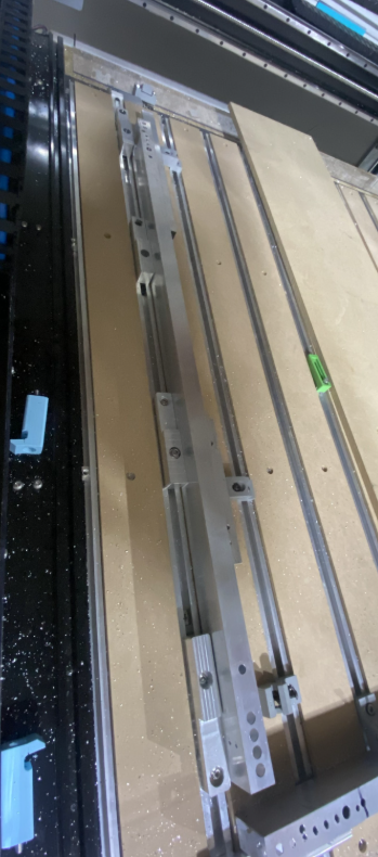
We’re machining this 1"X2" X.0625" tubing with a bunch of holes and pockets for Robotic parts. Tubing length range from 24"-39" long. The hole locations are consistency off .012"-.015" off centered on the 1 inch side at 38" length. When cutting holes on the 2" side, its location is better at .010" total variation at the end of the of 38" length. At location near zero, the location is about .002" - .005" off.
We have jig alignments to make sure the part is parallel to the spindle. When checking it with dial indicator, it has total .003" variation over 40" distance, which is pretty good IMO.
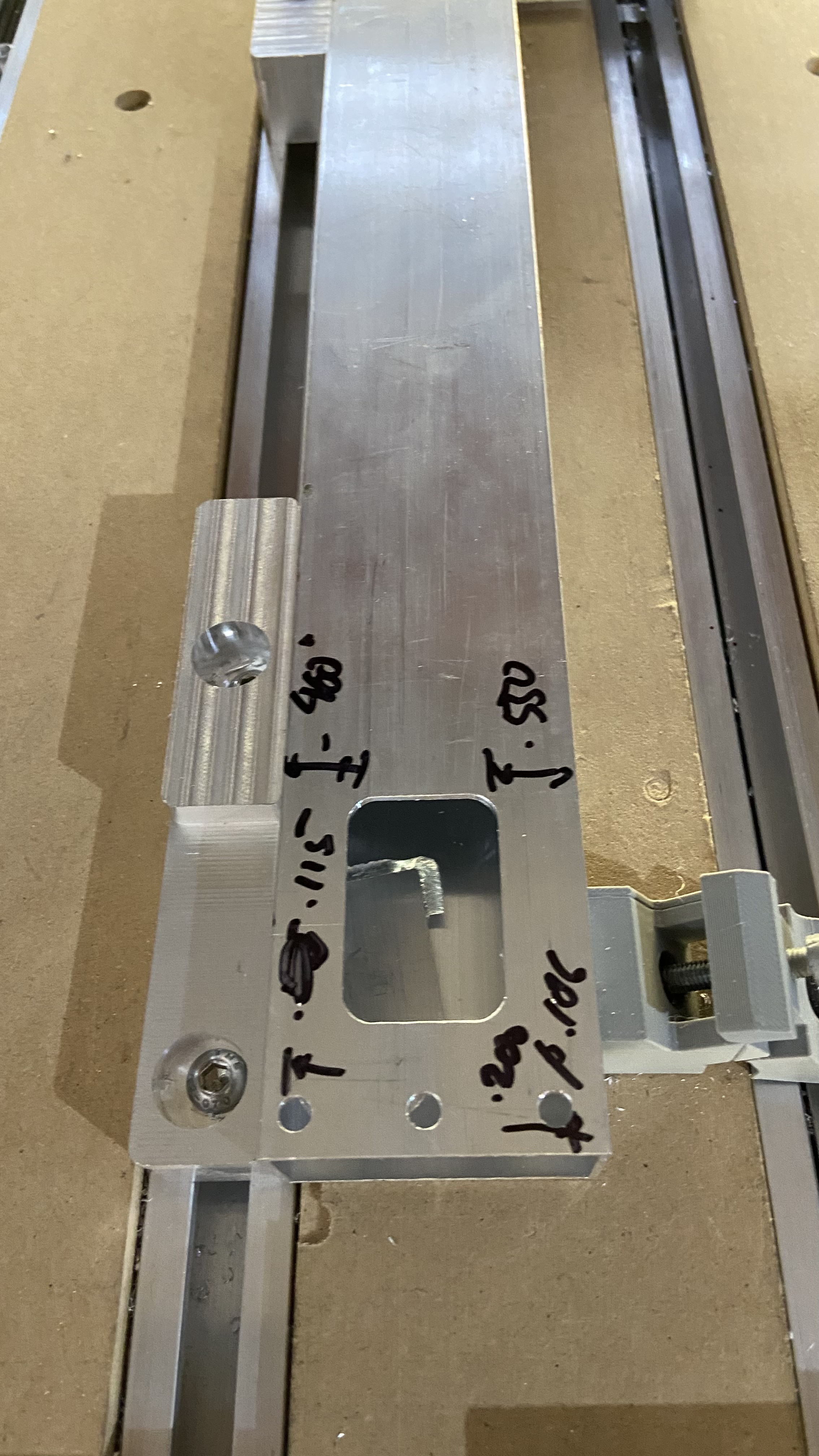
The only thing I can think of is how I clamp this part? Maybe the tube gets twisted or deformed. I guess I can clamp it then run my indicator to see if how square the workpiece it to the spindle?
We’re using 4mm, single flute, up cut EM. 20000 RPM, 30 IPM, full DOC, with ramp entry. The cut was decent, the surface finish is great, but dimensionally was off.
Am i and the limit of the SO5 capability? was hoping I can get .005-.010" total variation for location tolerance.
Question for you: How do you make sure your jig is parallel to the Y-axis? Do you sweep that with a dial indicator? Did you machine it in place?
And sweeping the part is never a bad idea. Extrusions may not be as straight as you think. We have to QC check ones we use on a granite table and reject a certain percentage of them because of warp.
I mounted a dial test indicator on the spindle and swept the Y. They are within .003" over 40" length. Same with the X. I’m just going to cut it in and see what that gives me.
Even if the tube is warped a little bit, the clamp should biased it against the Jig’s wall, unless the clamping is somehow twisting the tube, which is possible.
Vibration and chatter could affect that too. This thin wall tube is pretty ringing like crazy. I might create a sacrificial plug that I can use to support clamping.
Are all the cuts near an end? If so, could you do one end, flip the part around & do the other end?
This keeps all the machining near the origin where the variation would be much smaller.
Although you would need to ensure the lengths are right on.
Yes, the cuts near the ends were the ones +/- .012 ish. We could flip it and do 2 ops, but that was the hope of getting 48X48 Router, otherwise we just do it in our Tormach, which what we had been doing before SO5. Feels like SO5 can be dialed in better than +/- .012"
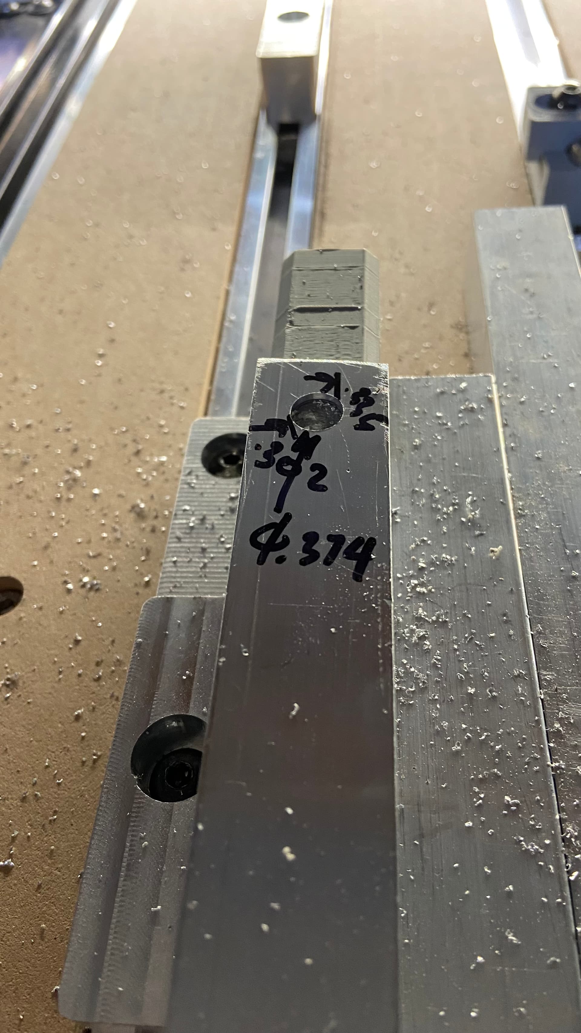
Hole size was consistently off by .004", which when I compensated in the CAM, they came out perfect in the machine.
I might do different hole sizes and see if the amount of offset is consistent, If that is the case, maybe there is something weird with BitZero ing the spindle? I have Haimer3D for my Tormach, I might try to use this and compare. Is there a way to do work offset on the Carbide Motion?
Have you tried to calibrate the axis in the grbl settings yet?
In theory you shouldn’t have to with ball-screws but if your chasing tolerance it’s an option.
You would do it just that same as the belt drive machines.
Cut a square. The bigger the better. Close to maxing out your calipers. Measure the square. Do the math. Change grbl steps per revolution for both axis and retest.
I think it’s time to just directly measure/sweep the extrusion, at the height it’s being machined at. You can try to control the variable you know about, but ultimately, you gotta go to the source to figure out if there’s another issue you didn’t expect. And the source in this case is the top of the extrusion, not where you’re clamping it.
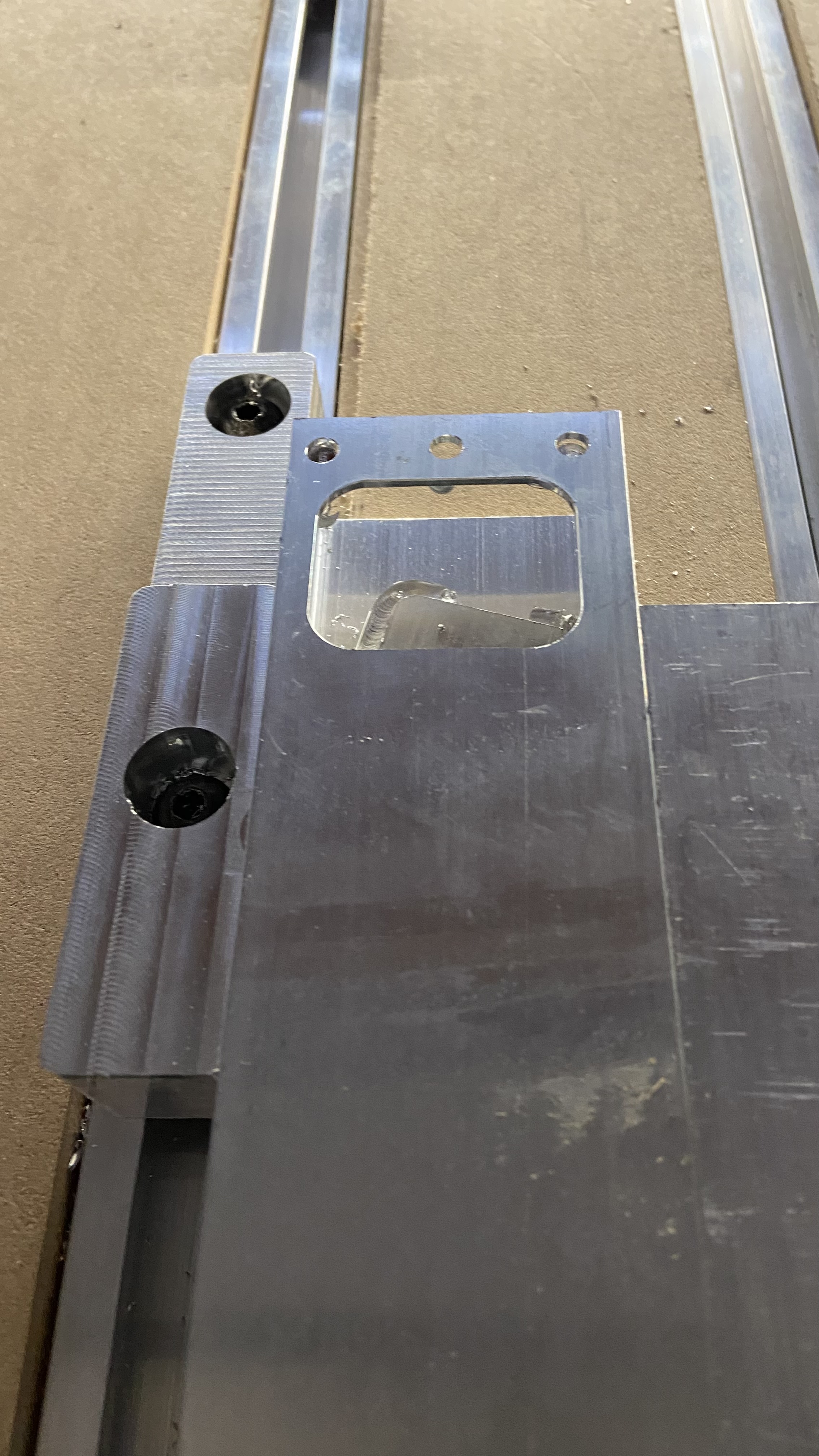
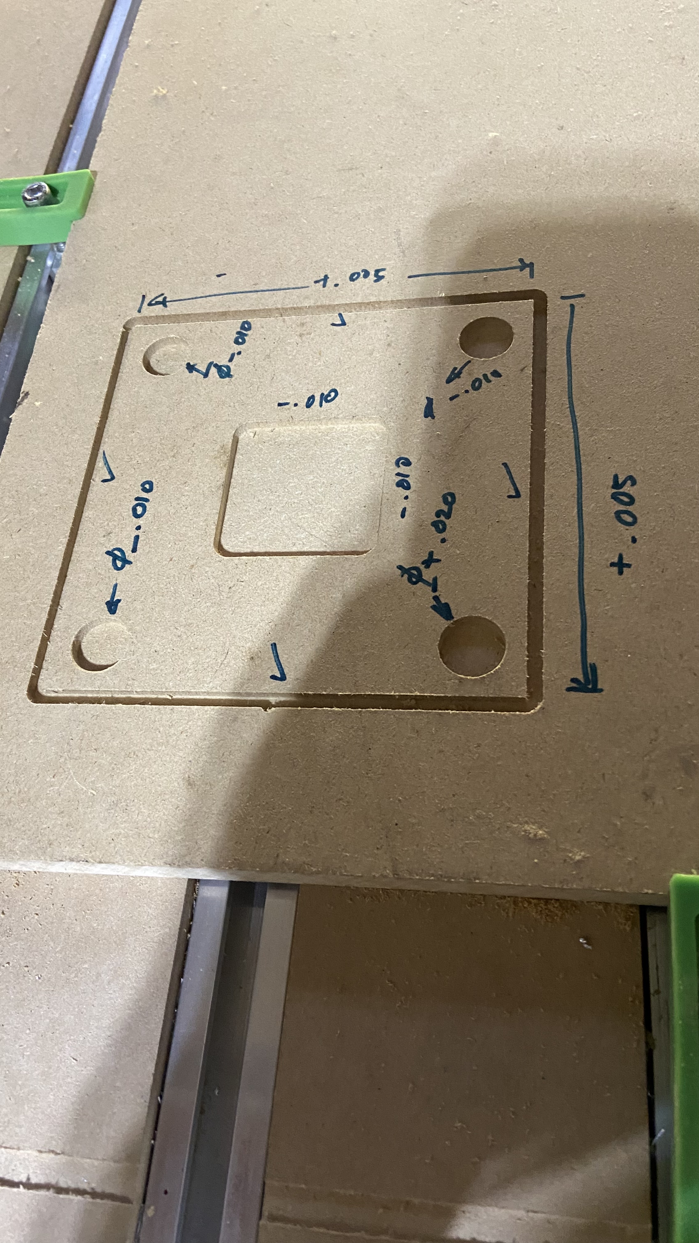
Slots are still on the smaller side about .010”. Outside contour was about .005” bigger, which I would be OK with. CAM tool profile looks normal to me.