I’m experimenting with Solidworks CAM using the Hawkridge Post Processor. When I run the file, it asks for the tool and does the homing routine and the like. When it starts the cut though, it the motors make a pretty ominous sound and it doesn’t look like the spindle is moving, so I shut down the machine right away.
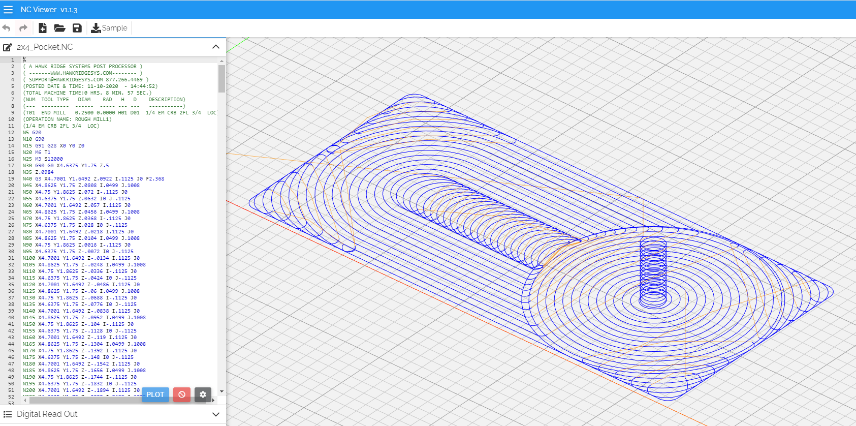
I don’t know GRBL or GCode very well, but the code is using “I” and “J” commands for contours. Not sure if GRBL supports this. Also, noted that lines N45 - N700 don’t have a “G” command at the beginning, then subsequent lines have “G1” and “G3” commands sprinkled in. I’ve posted the Gcode if anyone would like to take a look and share some insight.
Has anyone successfully used Solidworks CAM with this Hawkridge Post Processor?
but the ominous sound comes from the fact that the feedrate during that initial helical ramp is set to…2.368 inches per min, so the machine goes extremely slowly
N5 G20
N10 G90
N15 G91 G28 X0 Y0 Z0
N20 M6 T1
N25 M3 S12000
N30 G90 G0 X4.6375 Y1.75 Z.5
N35 Z.0984
N40 G3 X4.7001 Y1.6492 Z.0922 I.1125 J0 F2.368 <= this F command here is not right
Double-check what feedrate you programmed ? 2368mm/min would seem more likely, or maybe it was a feedrate in [unit per second] that was not properly translated into the G-code [unit per minute]?
I’m looking through the settings to see why the ramp-in is so slow. In the meantime, do you think settings that slow are problematic for the machine? Such a slow feedrate probably screws with the speed, but is it concerning for the motors or anything?
Also, do you have any feedback on the comments about the “I” and “J” and “G” commands?
G1 = Linear move at defined Feedrate
G2 = Clockwise Arc move
G3 = Counterclockwise arc move
Those G-words are Modal which means that once you set G1 mode you don’t have to explicitly call G1 again until it changes (G2, G3, G0, etc).
The I and J define the center point of the G3 or G2 arcs on the XY (G17) plane. I is the distance from the start point to the center along the X and J is the distance from the start point to the center along the Y.
Here’s a nerdy spreadsheet calculator I made to check if the arcs are GRBL safe. There’s nothing wrong with your arc, though.
Nah, the stepper motors are fine to just run at an arbitrarily low feedrate (after all when jogging by small increments manually, that’s what they do), but it just won’t make sense from a cutting standpoint (moving very slowly while the endmill is still spinning at 12000RPM = rubbing the tool = bad)
I forgot to mention: you may want to check if you can get rid of that initial G28 command on line N15: this executes a homing movement, only to come back to the defined X0Y0Z0 right after, I’m not sure I see the point of doing that (and it sure scared me when I ran your file for a check, and I hadn’t noticed it in the code)
Thanks for the insight Neil. I need to continue with my Gcode education.
Any reason that Carbide Create doesn’t us the “I” and “J” definitions?
Still trying to determine the Feed issue in the program; I don’t see why you’d ever have feeds that low. Looks like line N15 is for tool change, but I’m not sure why it goes home for that.
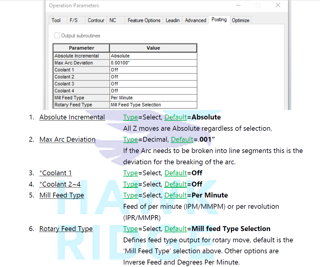
I’m curious by nature, so I downloaded the Hawkridge PP for a quick look, I could not see anything weird but there is this “Mill Feed Type” setting, you could check it’s properly set to “Per Minute” ?
Yeah, I noticed that and I have the setting as “Per Minute.”
I’m using a roughing strategy called VoluMill (which seems is the Solidworks version of adaptive clearing). Looking further into the operation settings, it looks like the spiral entry is a percentage of the leadin feedrate. The leadin feedrate was set to 10IPM and it gave me F2.368 for the spiral. When I set the leadin feedrate to 100% (72IPM), it gives me F17.053 for the spiral. That’s 23.68% of the leadin feedrate (same as the 10IPM).
So, it looks like that’s the issue. There’s also an option to set a minimum feedrate for the spiral entry, but it also uses that minimum for the rest of the operation, so it doesn’t incrementally increase the feedrate for hogging out the pocket. Is that gradual feedrate increase beneficial though? Also, what type of feedrate would one look for during this spiral entry? BTW, I’m just trying test cuts on a pine 2x4 with setting 21000RPM @ 72IPM.
For a spiral entry at relatively low angle like that, I would use ~70% of the nominal feedrate or so. In pine this will not be a problem anyway, pretty sure it would still work fine with 100%.