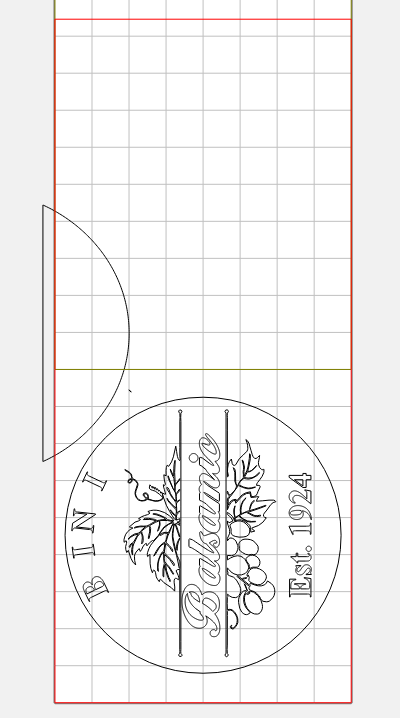
I designed a Balsamic vinegar barrel rack for a friend. He has 5 barrels of different sizes.
It’s 10’ long with slots for the barrels. I didn’t want the slots for the barrels to be between the tiles because I didn’t think I would be able to line them up precisely.
It would be great if each tile could be a different size.
I did get it to work work but it was difficult to come up with a tile size that would cut the slots without being in 2 different tiles.
Is there a way to specify the tile size of each tile…
I think if I were doing this, I would skip the tiling function & do it the old fashioned way.
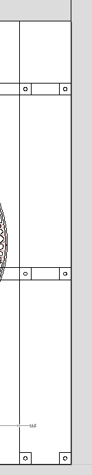
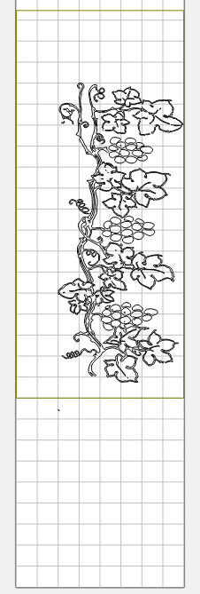
You have 7 distinct decorative features along the board, as well as the 6 cutouts for the barrels.
I would set it up so each ‘feature’ is cut in a single setup. (Or several if they fit.)
Keeping in mind that when you “Set your zero” on the job on the machine, you do NOT have to set the value to zero. You can type in whatever value you want. You have your “zero” in the design in the center. I would likely put mine in the lower left, but it is truly arbitrary.
Figure out which chunks you can fit in a setup, and pick a point you will call your “zero” for aligning that chunk. Write down the coordinates, and use that as your “zero”. For example, with the zero at the center, the lower left corner is -4.0, -60.0. Your next index point might be -4.0, -51.0
Since no 2 objects have to fit together perfectly, you could mark your index points with a tape measure & pencil. Set up a fence along the left side to slide the part along, and Just reset Y when you move it.
I have 32" max, but I always stay with 30". I liked the tile feature because I only need one drawing. I did one the old fashion way. Can’t remember how many drawing it was. The tile system worked better for me. I had to move one of the barrel slots about 1/4" to make it work. It just would have been a lot easier if each tile could have had a different size.
I tried to make drawings that were the right size to fit.
Thanks for the suggestion
There is no one “right” solution. Whatever works best for you.
Although my solution only needs one drawing as well. The catch is getting used to setting your “zero” to a point that’s not “zero”. And keeping track of the index points each time you move the part.