From a topic on the Facebook Page
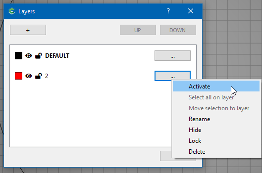
Eric Stein
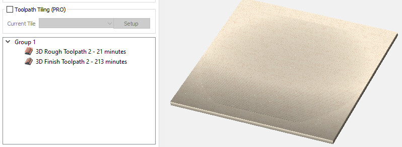
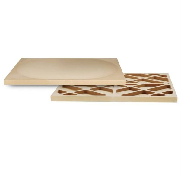
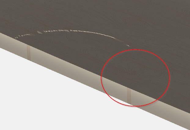
My nephew is making a guitar and we have used my S4 for a few of the parts. He needs to very slightly bow the top of the body (I know that’s not true luthier terminology!). He would like to cut out a sphere segment to use as the “mold” to hold the top for gluing. Anyone here done something like that? First pic is a "depression/bowl) that’s a little hard to see. Ive done some google searches with limited success. Thanks
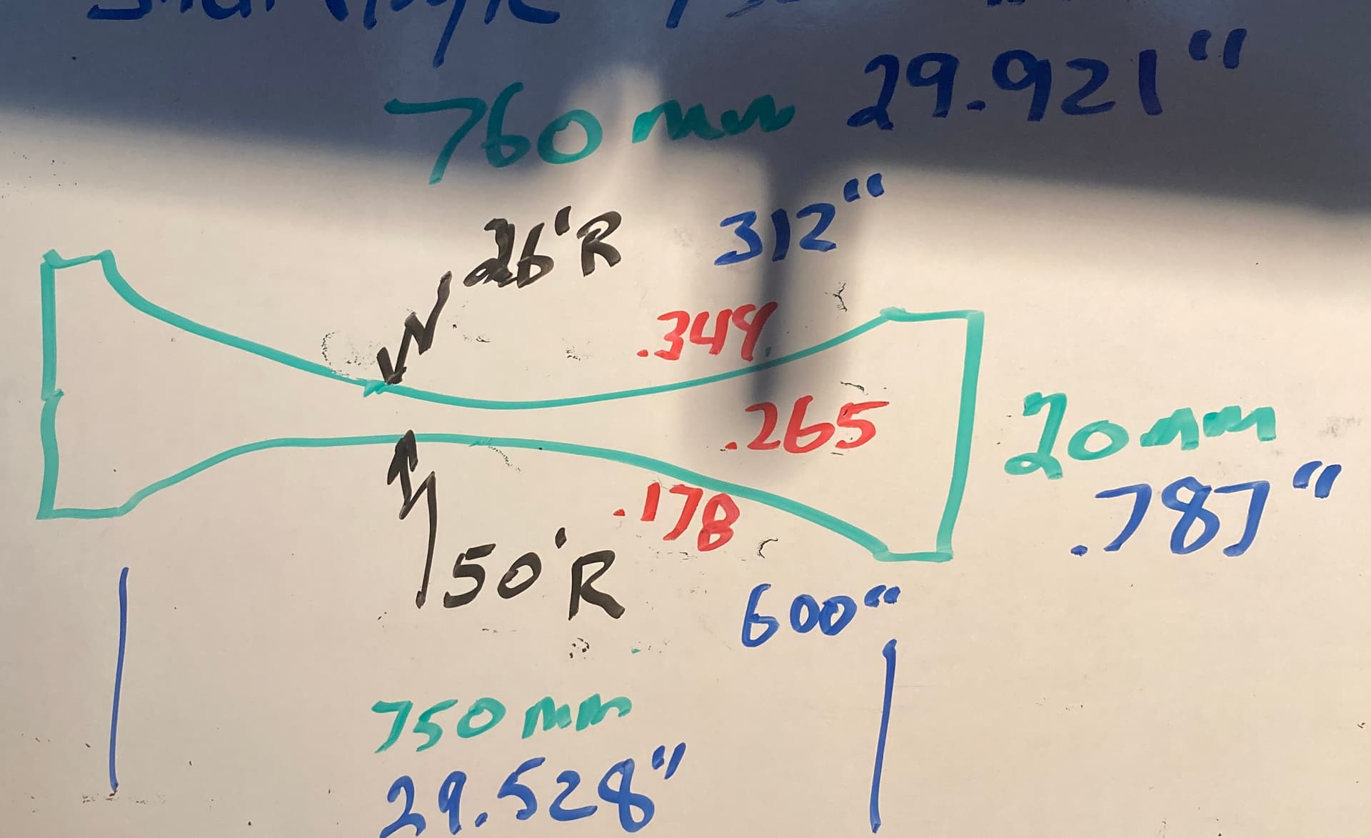
The dimensions of the board are 20mm x 760mm x 640 mm. The dished portion is on a 26 foot radius. My hope was to be able to do the other side on a 50 foot radius. Im not 100% sure there will be enough material left after the 26 foot radius is carved in to accommodate the 50, but it would sure make it a lot more convenient to have both on the same board.
OK. First we have to do a little math. Convert mm (green) to inch (blue), and feet (black) to inch.
Then determine how deep the depressions are, and how much material left in the center. (red)
I see a little bit of a flange in your picture, so I will use 750mm as my spherical section diameter.
Start a new CC file.
Set your Job Setup to
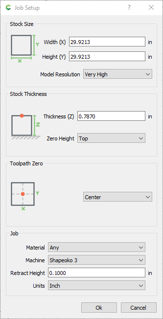
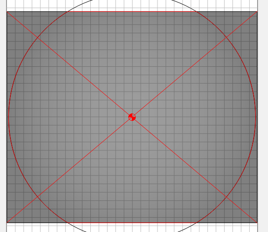
We make it a square so the entire circle is within the bounds of the workpiece. This is necessary to create the 3D shape. Otherwise it will try to round off from the flat edge that gets cut off.
Create a Circle 750mm in diameter (Type 375mm in the Radius field, and it will convert to inch)
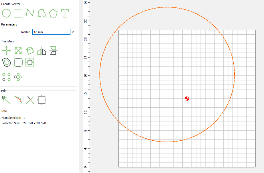
Create a Rectangle your actual stock size (760mm x 640mm)
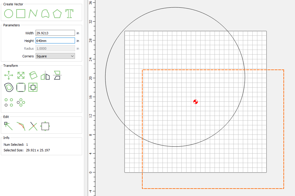
It doesn’t matter where you create them, we will align them next.
Select one of the shapes, Select Align Vectors 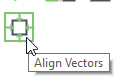 Then select Align Vertical & Horizontal
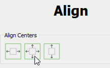
Select the other vector & do the same thing.
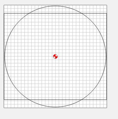
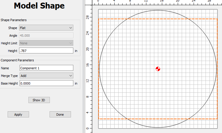
Now to model the shapes. In the Modeling tab, select the rectangle, and Add Shape 
Create a Flat, 0.787 Height component.
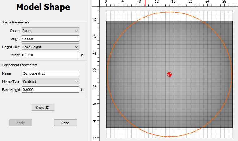
Now select the circle, and create a round, 0.344 Scale Height, and Subtract
When I hit apply in Build 757, it takes a while to calculate. Be patient & wait ![]()
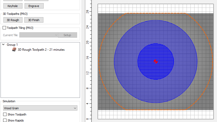
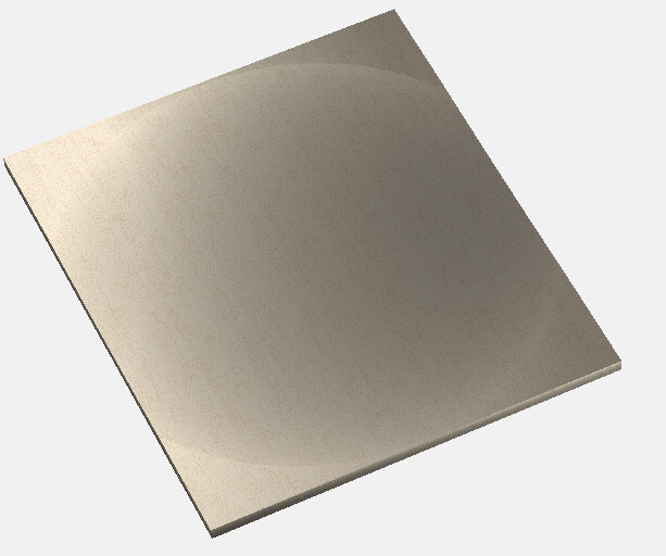
Switch to the Toolpaths tab, and select Wood Grain for the material in the Simulation panel at the bottom. Switch back to the Model tab & Show 3D. You’ll have to rotate it around to get an idea of what it looks like.
Now let’s do a sanity check to make sure the shape is correct.
Back on the design tab, create any shape that has an edge going through the center point.
Go back into the Job Setup & change the height to 780mm (14.9606")
On the Model tab, select the new shape & create a component that is Flat, 0.443 height, and Equal Merge Type.
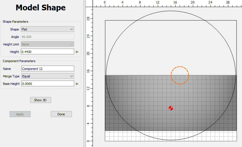
Now Show 3D, and look closely at the edge that crosses the center of the dish.
You can see in this area the “gauge block” that we created ‘washes out’ and shows no edge either raised or depressed. This indicates that our material is the right thickness in the center.
You can delete the last component in the Model tab, and the vector. And go back & change your stock height back to 760mm.
Save the file as something like: Arch_Top_Jig_26R.c2d
Now do a Save As… and name it Arch_Top_Jig_50R.c2d
You are now working in the 2nd (50R) part. So just delete the 2nd component (Subtract), and recreate it using 0.178 for the height to get the 50’ radius.