I did a quick scan and couldn’t find this anywhere.
There are times when I have the need for boards that are bigger than my available stock. There are all sorts of techniques for “Stretching” a board, or splicing two boards together end-to-end. Usually, they involve some mechanical mechanism to overcome the inherent weakness of butt joining.
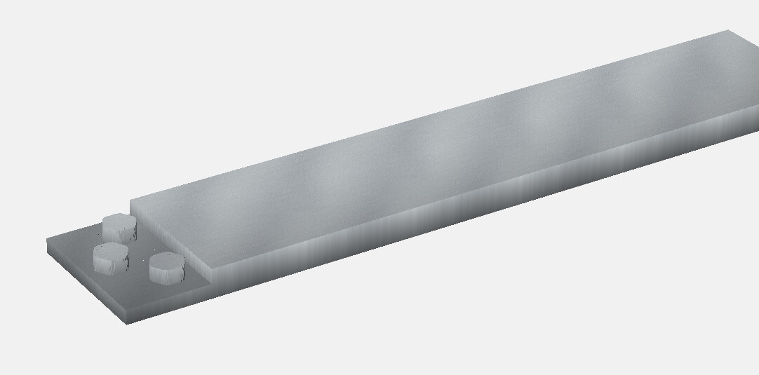
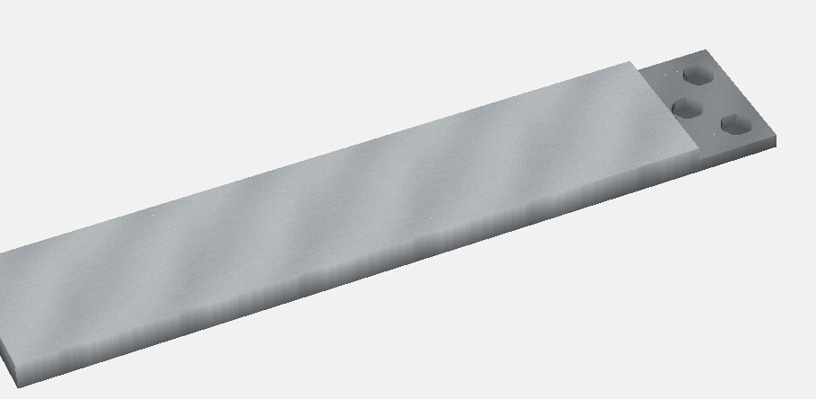
I wonder if anyone has used the CNC to mill out a perfectly matched splice pattern on the end of two boards, that would allow the boards to be joined and provide multi-directional support. The idea would be to create the equivalent of a lap joint, but with matching “teeth” that interlock - providing both an s-load of gluing surface as well as mechanical resistance to racking.
yes and it works well. just leave a little bit of room between the top of the “tooth” and the bottom of the upper lap. this will help them come together well, just as if you are doing an inlay.
I don’t really understand the motivation. Are you trying to make it easier to index? To load the joint before the glue is strong enough? Otherwise the weakest feature is still the two butt joint faces, not the lap joint face.
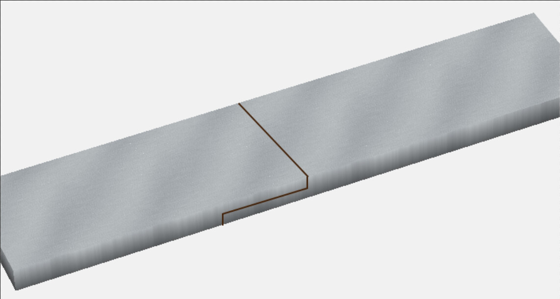
I would think if you were really concerned about absolute strength, then some sort of deep triangular finger joint would be the best.
I’m looking for stability, not only from separation - which a scarf joint or regular lap joint would provide - but also from shear forces. It seems to me that the cross members would provide additional gluing surface area as well as mechanical resistance to pressures coming from the sides of the wood (think edge load).
As I see it, the lap joint shoulders are only there to provide racking resistance across the joint. The glue surfaces do all of the holding…none from the butt joint portion.
I still don’t think that’s how it works, Gary. Now I know I don’t have enough personal experience, but from my reading that’s not how the joint will fail.
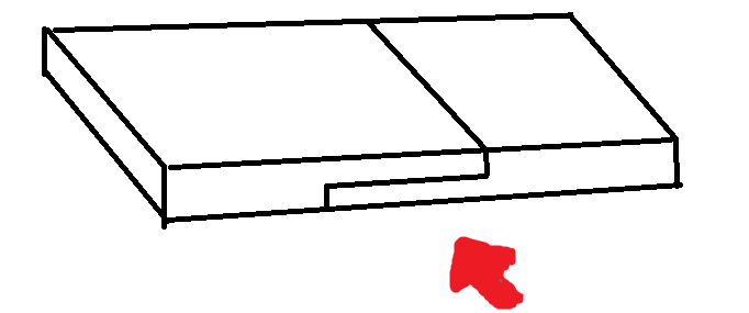
I think you are saying the force is like this:
In a basic lap joint, you end up with glue like this, represented in blue:
From what I read of other people’s tests, when it breaks, it can break partially in the glue plane, but typically also include a lot of wood a little distance from the glue plane. So the wood is what is failing, and more glue is not helpful, unless you are really trying to make a composite material via your glue.
As long as it is the wood that is failing, it doesn’t matter if the wood is from one piece of the lap or the other. It makes no difference. The break can include the button or the recess, but it doesn’t increase the amount of wood there is through the breakage plane.
Now if you include a straight grain dowel, I’d say that is better than the button. The button is not acting like a dowel though because the grain orientation is not aligned right.
Admittedly I am not particularly well versed in joinery. My experience is mostly based in boat building and composites. When cold molding a wooden boat with modern materials, some form of lamination is generally the play, but none the less, the various layers of sheathing are generally scarfed together. Plasticity is always a consideration, and an adhesive scarf joint(variation to be determined by anticipated loading) functions well in complex loading conditions, shearing force, axial force, and bending moment. The same concept is generally always used in fiber composite joints as well.
Its also worth noting that pinning, clasping, keying, and other mechanical additions can potentially decrease load capacity.
Solid timber structural beams, like those used in historical buildings, have a whole host of other considerations that my old books probably don’t address. You’ll often see some form of splice and mechanical addition on these.
When I get back out to the shop, I’ll try to dig up a couple books and see if I can find any suggestions for you.
Please don’t take this post as argumentative, but I just want to emphasize some of the points you mentioned.
It seems high ratio scarf joints can be quite strong. From that particular dataset, a scarf ratio of 12:1 is pretty close match to the stiffness and strength of the native wood. Higher scarf ratios seem to be a bit stronger and stiffer than the native wood. It seems to exhibit composite material effect at the high scarf ratios.
I think a limitation of a study of historical structural beams is that many of the techniques came from a time when adhesives were much less capable, when things like iron / steel fasteners or plates were more limited or not even available. Add to that the demands of a construction / forestry worksite. What ended up being done may have been the best practice for that time, but I’m not sure it translates wholly to our times. For example, a keyed scarf joint is very nice to look at and is able to be dissembled, but it only has about 1/3 the mechanical properties of the native wood (reference). That means for it to work, the rest of the beam is very much overbuilt. Yes, 200 years ago they couldn’t make a glued laminate beam onsite at a church or warehouse so they used a keyed or pegged scarf joint. But that doesn’t mean that is best option today for someone in their workshop working with dried wood, with the availability of modern adhesives (and CNC and other machine tooling). Today we can make something pretty close to a glued laminate board / beam, or at least pretty close to the native wood.
For plywood joints, where you typically have both end and flat grain, 8:1. For timber, where you typically have all end grain,12:1. For fiber composites, a minimum of 12:1. These are general reference values used throughout the industry.
Builders generally think of wood just as any other composite. Trees experience loading that is predominately aligned parallel to the grain, leading to primary properties, but also experience loading that is not aligned with the grain, leading to secondary properties. One could think of a tree as similar in performance to an engineered composite tube. Imagine a tube that is primarily comprised of unidirectional fibers orientated parallel to the length of the tube, then finished with a +/- 45 biaxial fiber composition.
As far as I know, a plain adhesive scarf best joins these primary and secondary properties while developing bonding surface area. Because of the latter, you typically ignore the direction of load and scarf the largest side of the lumber, more surface area.
I scanned the index of my “boat builders bible” and found no listing of additional joints.
Perhaps an easier way is use a full length thinner board for the backing of the two halves. You still have a “Butt” joint, but two boards that have been carved and held together. I don’t see any reason for get real fancy in creating a scaf, finger to button joint and the tedious time used to create such. Tom