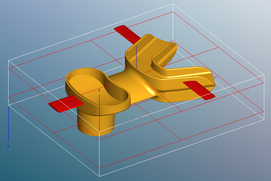
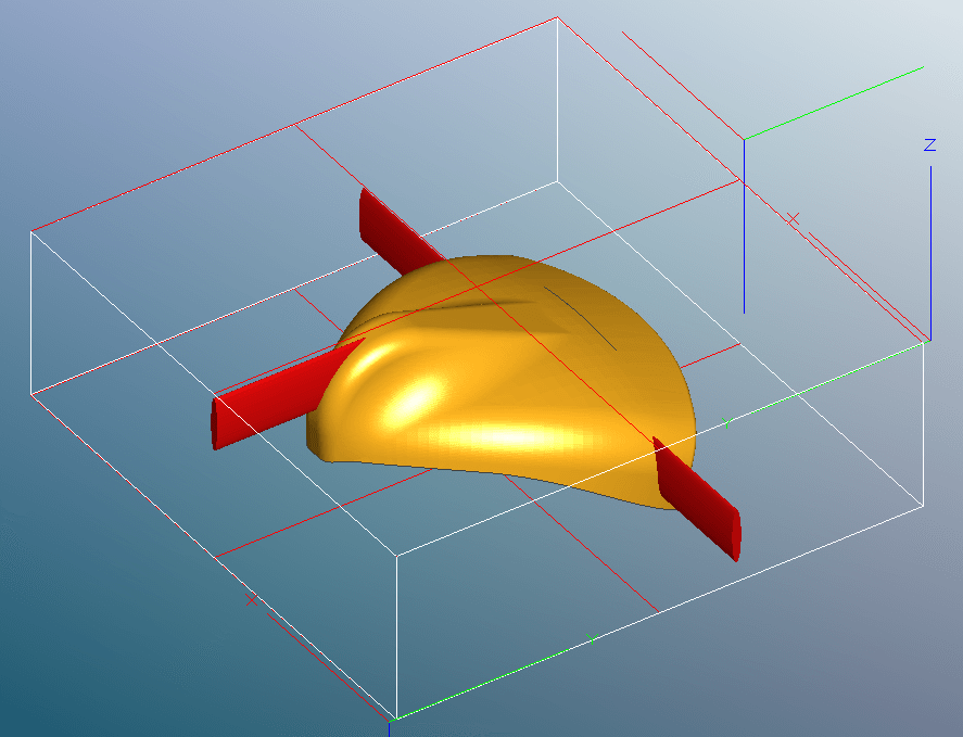
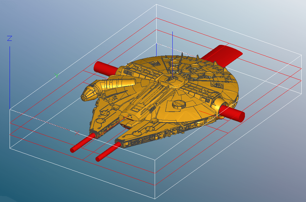
Confirm you need to design in splines to attach the part to the original stock so the part does not fall through when milling. I assume you need two, one for each end.
Is there any conventional wisdom or rules of thumbs for sizing the splines?
Yes, they are needed. If you just use two and they are round and small, the part can twist around them like an axle. I tend to make at least one support a little wide, or add another support or two at the side to help immobilize the part.
A lot depends on the geometry of the part. There have been a few discussions of supports over on the MeshCAM forum at
Here are screenshots of some of the supports I’ve used. I only have records of supports I saved in mcf files–in other jobs I just did them as I needed them. But on some jobs I saved multiple orthogonal views of the workpiece and laid out the support locations in CAD to get the precise dimensions and locations that would fit.
Oftentimes when using supports, you can get by with pretty small supports if you plan the machining carefully. Setting max depth at the bottom of the stock helps a lot. On the first side, the supports really aren’t needed until the very bottom of the roughing, because there is still a continuous area of stock underneath the roughing cut until the very end. And even then, the supports are the full depth to the bottom of the stock. when you flip the stock over, the only places having the relatively heavy roughing cuts are on top of the supports themselves, and the supports are still tall, getting shorter as the roughing progresses.
It can save roughing time by setting up the whole job with max depth at the bottom of the stock, calculating all the toolpaths and saving the roughing + finishing for the first side and finishing only for the second side. Then reset the max depth to just a little below the level of the supports (“below” as viewed from the underside) and uncheck finishing so MC just recalculates the roughing. Only save the second side roughing and use it with the second side finishing you calculated earlier.
And when using supports, it helps to make the “Geometry plus” margin just a little larger than the cutter radius–maybe 3/4 the cutter diameter to give some kerf for clearing chips. MeshCAM will only follow the supports out to the margin. Short supports are stiff supports and that helps the accuracy of the machining. Use a fine calculation tolerance (I always use .0001" for the final toolpaths) and MC will work well in the narrow kerf around the part. Leave minimal stock (.01" or .25mm) for finishing to minimize the cutting forces in that step. Roughing with 3D roughing, unchecking parallel roughing and roughing with a ball-end cutter help when doing 3D contoured parts. That will minimize the “terraces” that the finishing cutter needs to plow through.