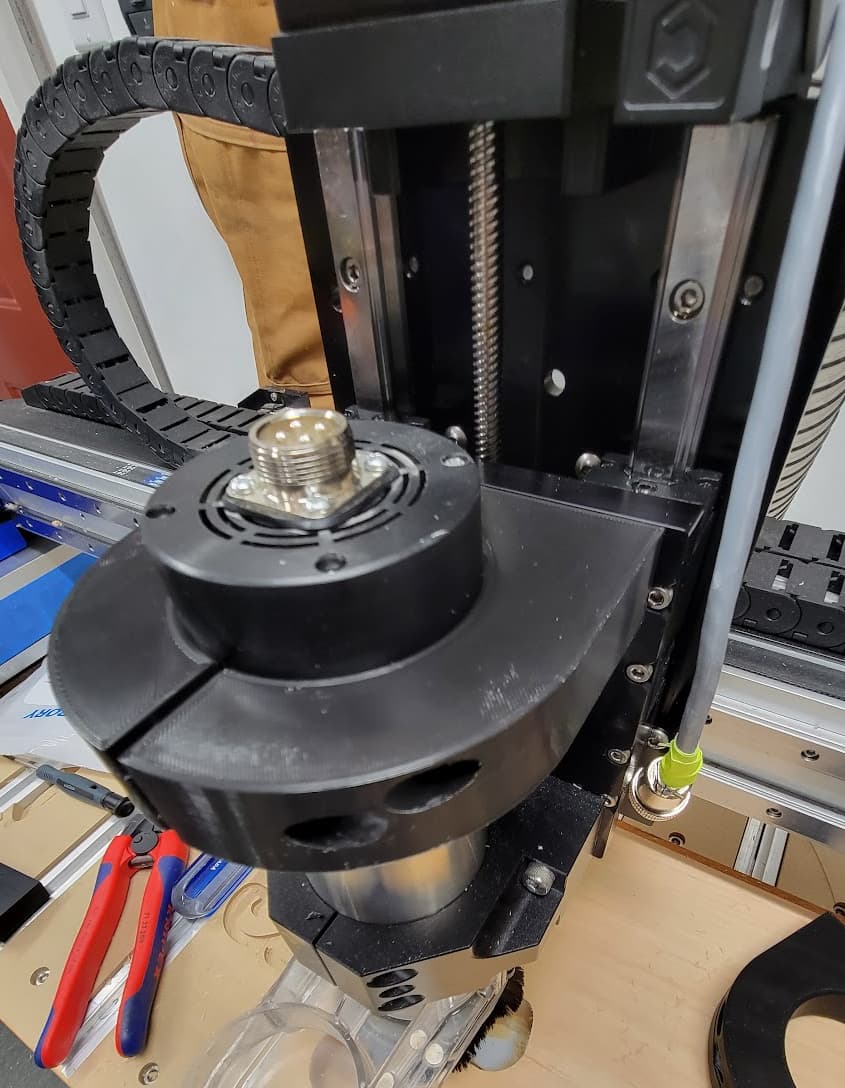
I’ve been using my C3D spindle on my Pro more. I’ve noticed that as I increase the load, I’m starting to get some vibration that I can see at the top of the spindle.
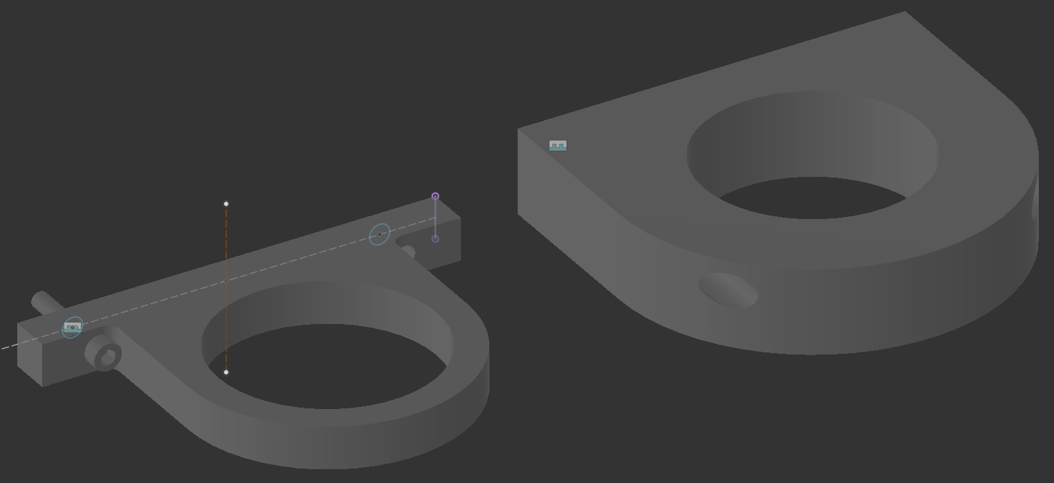
I’ve started trying to CAD something to take advantage of 2 unused holes on the stock Z plate.
I’m by no means a CAD wizard… The right is for 3D printing. The holes are rather close, and in order to make it from aluminum, I need to start making it quite thin to get clearance to mount the bolts.
The vibration is more likely to be in the linear rail rather than the mount itself. As much of a step-up the linear rails are in rigidity, they are still less stable that a hunk of aluminum that is over 1" thick.
When I first got my Pro, I pushed it to see what the limits are, and I determined the weak link for vibration to be the belts, particularly in the X axis as there’s not much mass in that direction to dampen the vibrations, and only a single belt.
Well I’ve got the 3d printed mockup almost done, just dialing in tolerances. I think it will help.
The movement I’m seeing is definitely the spindle body compared to the Z plate. I can probably reproduce it quite easily with some agressive cutting once I get this thing mounted, we’ll see how it performs.