Started project in wrong spot

Hi everyone,

I’m not sure what has happened, but I did a few small projects on my shapeoko 3 and they worked fine, but over the weekend I went to run a larger project and the machine started it at the far side of the working area and tried to keep moving away (back towards the initialization corner). I tired flipping the project in CC and redoing the toolpaths and got the same result as if I hadn’t reworked everything.

Can anyone suggest what I can do to correct this issue?

Where is the origin set in the file?

Where/how are you setting origin relative to the stock?

What does the preview of the 3D view in Carbide Motion show?

Please post your .c2d file, step-by-step notes on how you are securing your stock and setting zero relative to it and managing all tool changes and a photo showing an attempt at cutting still in place on the machine.

Did you do the correct XYZ zeroing before you cut?

1 Like

Hi @WillAdams ,

I’ve set the zero point center of the piece in the file as the stock an irregular shape. As for setting the origin on the stock its self, after initiation of the machine, I jog it to the center of the work piece, and set the zeros in CM.

I’m not sure how to see the origin in the CC preview.

The c2d file and pictures are attached. I stopped the machine as to not further mess up the wood.

Thanks
Chris

Argentina.c2d (660 KB)


You have a work piece size set to 11x35. The Y axis cutting area for the 3XXL is ~33 with 2 of those overhanging the front of the machine. I think you have a situation where the top of your graphic is past the reach of the machine. I would try to set the center of you board a few inches forward of the center of the bed. Set Z above the piece and try an air cut before committing to a real cut.

The orange box is an approximate 33x33 cutting area showing a 2 inch shift to the front.

2 Likes

Thanks for the feedback, however the issue that I’m having is the area circled in the picture is being done at the top of the cutting area.

I factored in the working area of the 3XXL when I was doing some layout.

Can you export the G-code and post it? The simulation in CC looks fine. Do you use a laser and possibly issue set-up codes that may have reset the coordinate system?

It is the red:

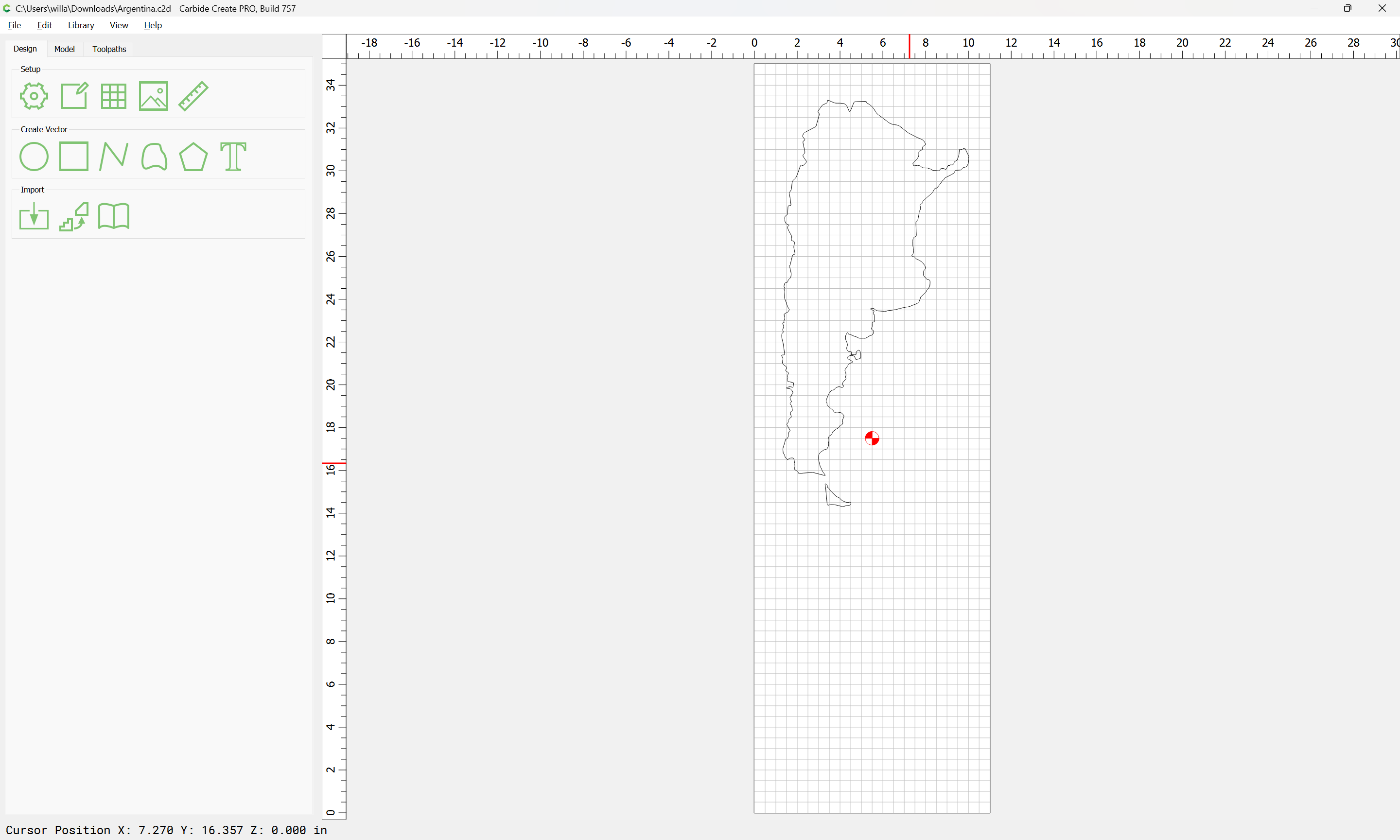
You have your working area set to 2" greater than the nominal working area of the machine:

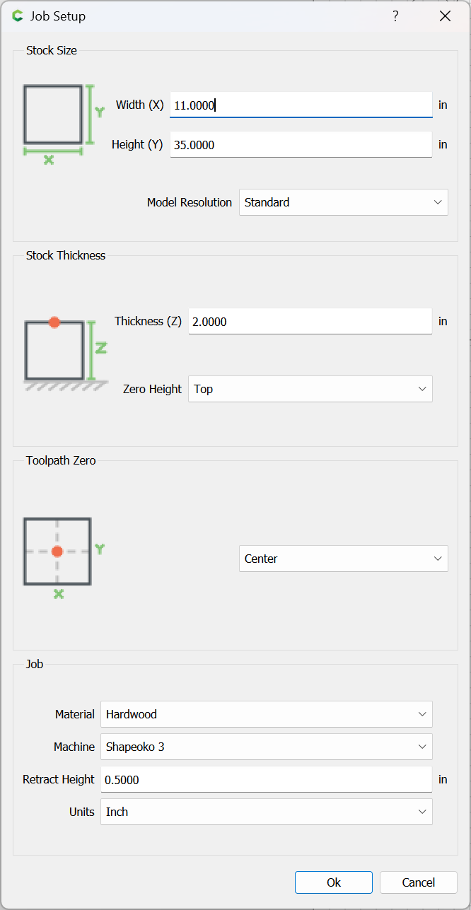
that should be reduced to 33" for Height (Y).

Are you using the center rapid position point to set center? Please note that that is not the center — also the 33" working area includes the overhang cutting area at the front of the machine.

Please see:

I would recommend drawing up the machine structure and working area using the Rapid Position points and setting origin at them and jogging around from them to see where the machine actually is positioned at for various positions.

It may be easier to cut this piece by rotating it and using the lower left as the origin so the excess material could just hang out the back(supported) of the machine. This would ensure the required cutting area was on the machine bed and reachable.

2 Likes

This topic was automatically closed after 30 days. New replies are no longer allowed.