As mentioned elsewhere I am replacing my blown Sparkfun controller with a stock carbide controller that came with my XL upgrade. I am in the process of wiring the harness into the steppers that came with my Sparkfun Shapeoko which of course have different color wires than the carbide harness.
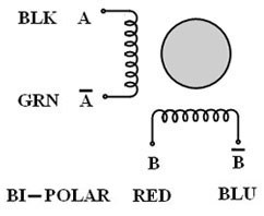
My steppers have the following color codes:
BLACK A
GREEN A_
RED B
BLUE B_
When I attached them to the wiring harness matching colors it didn’t work. I don’t see a wiring diagram for the Carbide controller.
I have never seen a wiring diagram for the Carbide steppers. Can anybody help me translate between the two color schemes?
Also on the Sparkfun unit you had to physically reverse the wires on one of the Y steppers. What do you do for the carbide controller to accommodate the Y steppers moving in the opposite direction?
the wires coming out of the stepper motor are blue, black, green. red
blue to pin 1
black to pin 2
green to pin 3
red to pin 4
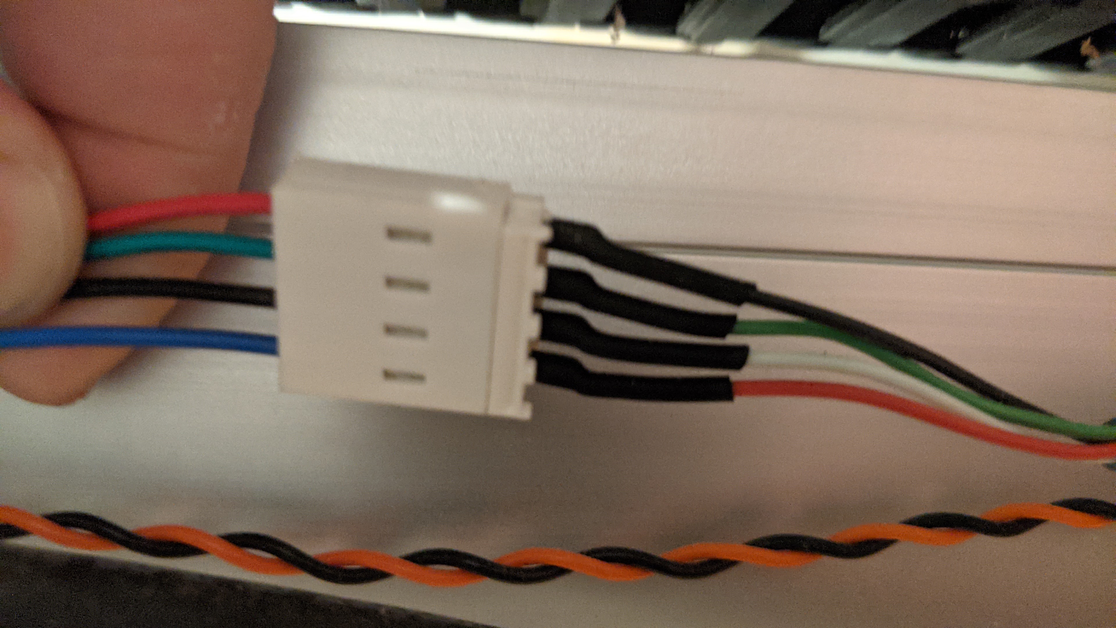
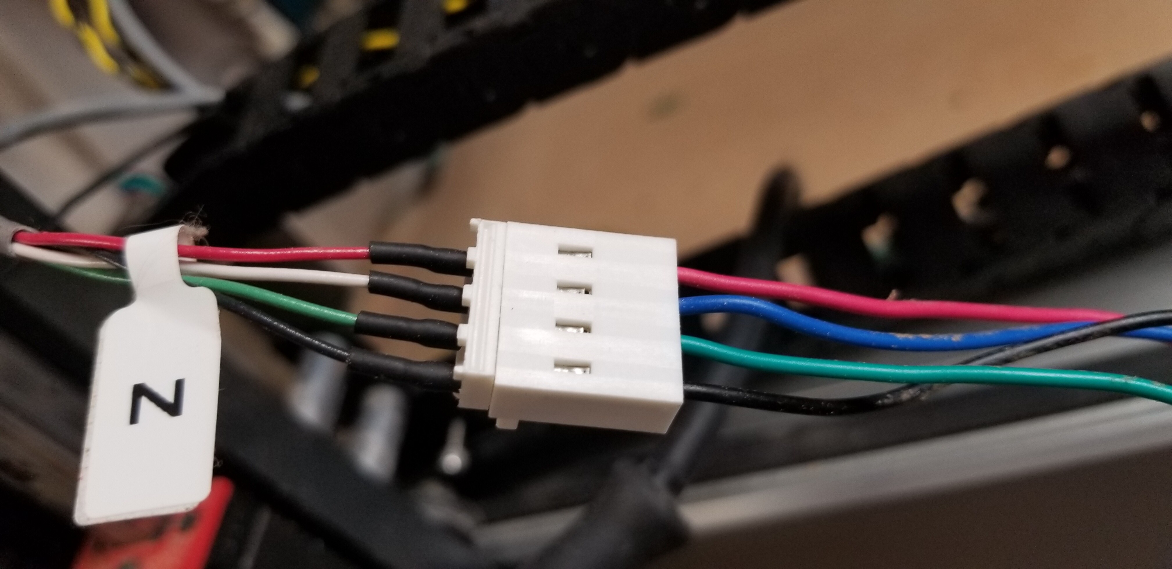
the wiring harness has them crossed (or at least mine were) red, white, green, black.
the order in my supplied harness were red, white, green, black
Will, the Sparkfun stepper just has bare wires. The wires go directly into screw terminals which are clearly marked with the motor wiring connections.
I had to attach the molex to the stepper leads myself and I just roughly tried to match colors but the colors are not the same on the harness (but it appears the Carbide motor colors are the same as the Spark motor colors)
Unfortunately in all the pictures in the XL wiring document the person has their FAT FINGER on the molex connection covering up the colors. Not real helpful. If somebody could just post a picture of the XL Z connection or X connection with both sides showing wire color it should be what I need. Near as I can tell from the picture of the Y connection they reverse some of the wires on the harness (but again the connection is mostly covered up by somebody’s FAT FINGER. Barring that If I knew which colors on the harness go to which coil on the motors I could figure it out.
Of course there are no schematics of the Carbide controller board or the motors. At least the Sparkfun board was open in that everything was clearly marked and the schematics were available.
The color codes for the wires at the motor is pretty standard (Except when they’re not ). Ring the pairs out with an ohm meter to ensure the phases are on the correct color pair.
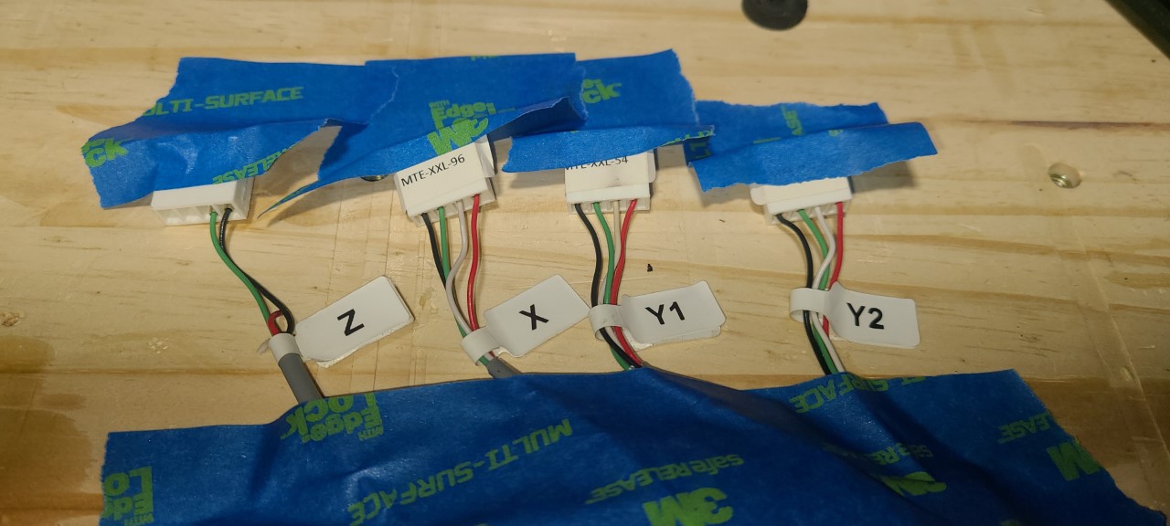
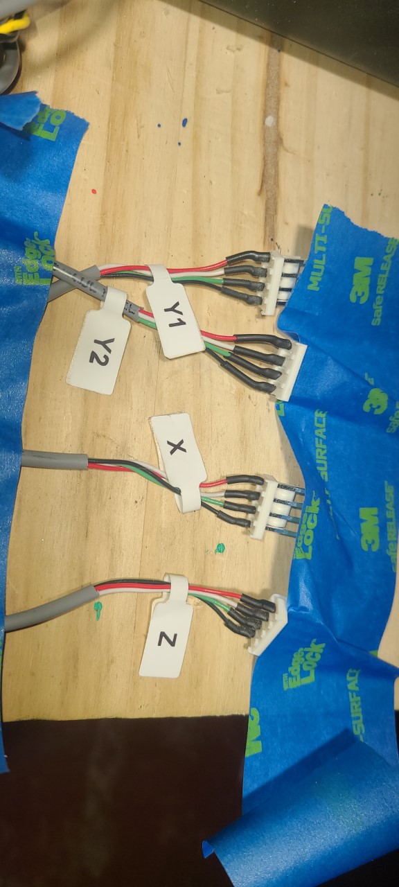
Which revision Carbide motion control board do you have? There are some pictures in this thread of stepper harness connections at the board. Feedhold (the definitive thread?)
Yep, read above, that won’t work
blue from the motor to pin 1
black from the motor to pin 2
green from the motor to pin 3
red from the motor to pin 4
if you got a harness like mine, the colors are crossed
I’m still confused. Please understand the molex in my picture was built by me. My steppers all have bare wires and I need to connect them to the highly engineered Carbide harness.
Any chance somebody could post a picture of the CONNECTED Carbide molex for X or Z?
I am trying to connect the Red - White - Green - Black male to my Red Blue Green Black wires (using a Molex that I make)
 ). Ring the pairs out with an ohm meter to ensure the phases are on the correct color pair.