Trying to decide if this is a software, hardware or user issue (probably user ).
I will state upfront that my 3D knowledge is very weak (which is why I have never covered it on my channel). I am putting some time into figuring it out and I am having issues getting STL files set up with anything close to decent results.
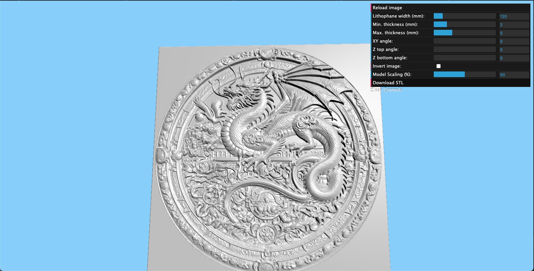
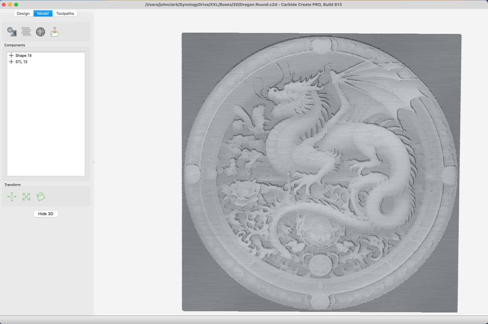
I have an STL file which has a nice amount of detail in it:
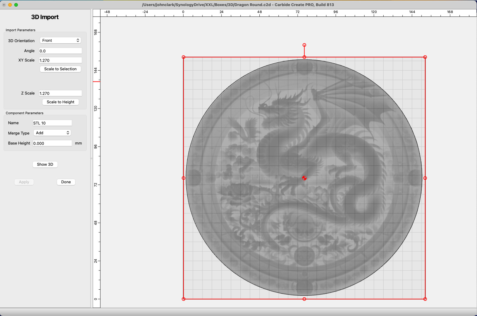
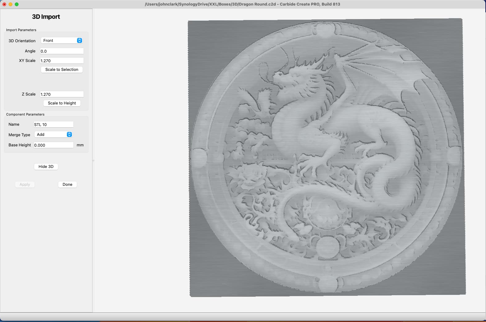
I assume this is user error of some form. I have tried scaling things to 1:1 but it still looks really messy. I have attached a link to the stl file below. Any 3D wizards that can shine a bit of light on what is happening?
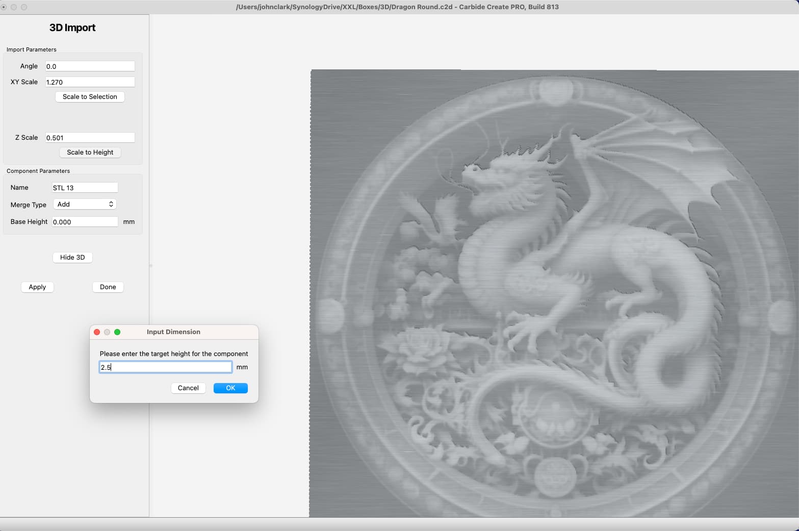
Maybe play with the import Z scale till you find an acceptable preview. Also on the stl download from Sculptok you might want to play with the scaling, min, and max bars until you get the best image possible. Also if you preview it in pine you can see it better.
I usually zoom in close on sculptok while playing with the slide bars. First to see what each bar dose, and second to find the best image. Good luck!
What is the height of the STL model? And what is the height of the carveable area?
If there is considerable material below the carved portion, like a built in base, it’s using up some of the pixels that represent height. Hope that made sense.?
Each white to gray to black color represents a height. And there are only 256 possible heights.
If the model is 2.56" tall, each pixel represents 0.01" in height. If the model is 0.256" tall, each pixel represents 0.001" in height.
You may need to trim the base off before importing the STL.
CC used to have a function to do this on import.
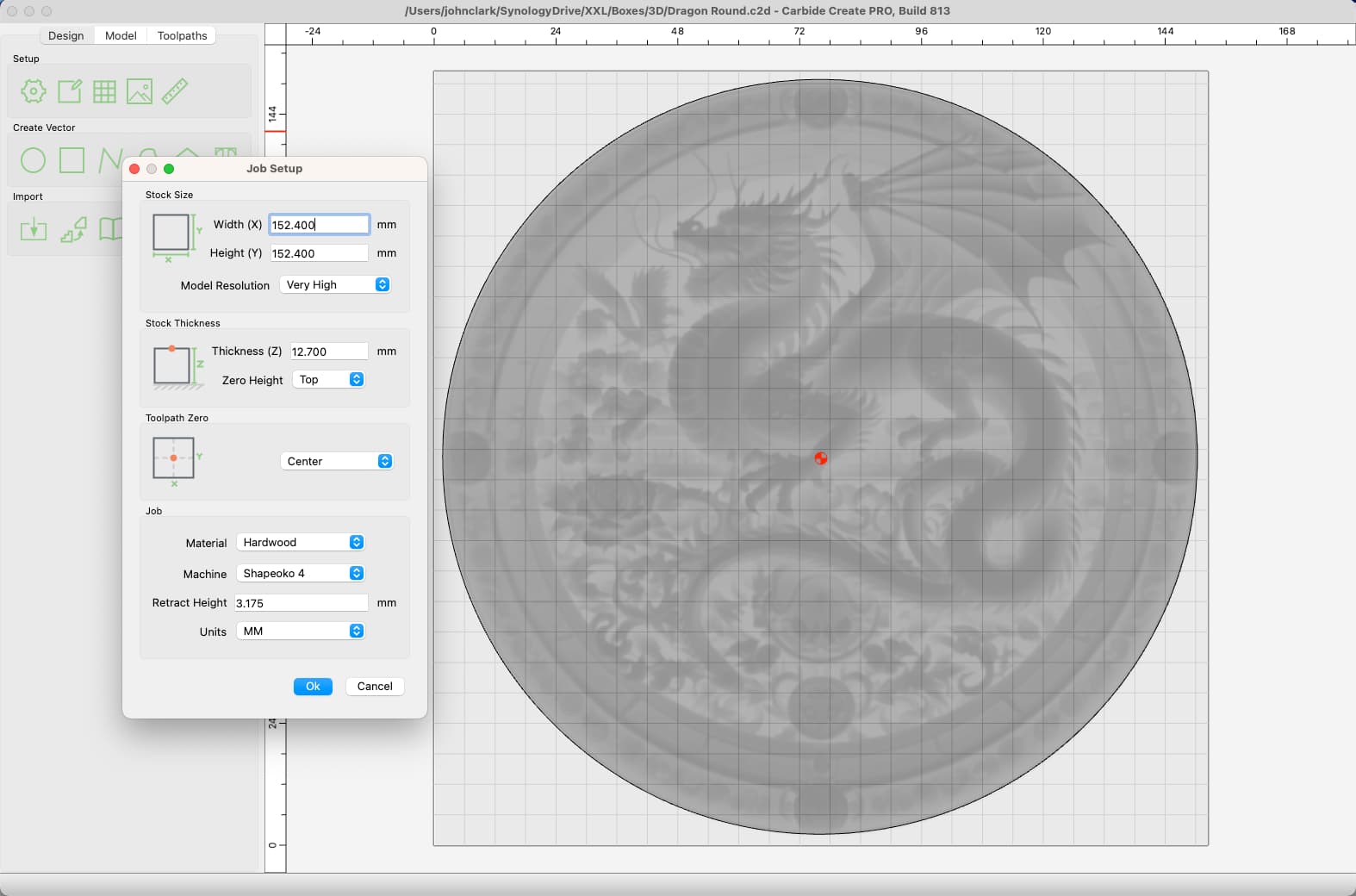
So if I am thinking about this correctly, if I scale to a height 3 mm (0 base height) then the difference between the highest and lowest part of the carve will be 3mm, correct?
The STL has it’s own min/max thickness, should my STL settings match my CC model settings?
I think I do get what you are saying about the shades/height/resolution relationship.
Since I am carving on a piece of half-inch wood, what is the best practice for keeping the height? Do I just set the stock thickness settings to 3mm, or is there a better way?
What I’m saying is, if the STL model has a built in base, you can increase the resolution of the height map in CC by editing the base on the STL (In some other STL editing software).
So if this a cross section, and curved bits are my design, chop the bottom half off at the dashed line & double your resolution on the remaining part.
Your CC height does not have to match the raw STL height. But CC will scale the entire height of the model. So, if this is say, 8mm tall including the base, the design is about 3mm tall. If you scale it down to 4mm, now the design is only 1.5mm. But if you trim 4mm of the base then import at 4mm, the design will be 3mm tall.
So you set your stock height to 4mm, import the model & cut with your zero at the top. No matter the height of your stock, it will cut the design down 3mm into the stock. Your actual stock might be much taller, but you’re achieving the 3mm depth you were shooting for.
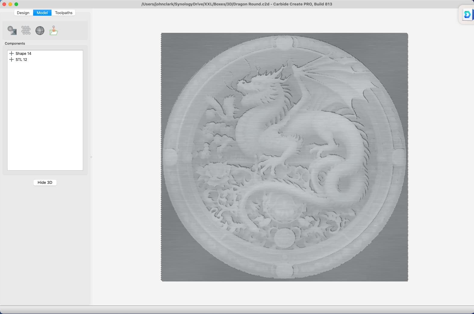
The remaining jankiness I would chalk up to the AI nonsense in the original image. At least I have a marginally better handle on how it works and what to look for.
Thank you all for your help and patience. Now I need to practice a bit.
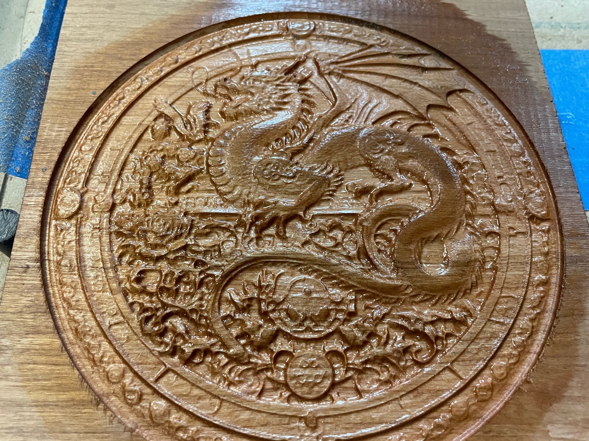
Thanks. I used a standard 1/8 inch mill for the roughing pass and a 1mm tapered ball endmill for the finish. This one I think (or something similar):
You get some nice precision with it and the 1/4 shank and taper let you bump the speed up considerably more than a regular 1mm endmill would be able to take.