I’ve been trying to test how imported STLs would work in CC Pro, and how accurate they’d be. While consuming several YT videos on 3D in CC, I’m still confused at how this might work. Any suggestions would be appreciated.
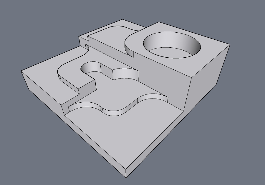
I can import a STL file, so as an example, this is a simple model, created with various steps. It is 1" high, and using 1/8 and 1/4 increment steps to test how accurate the final CNC results would be:
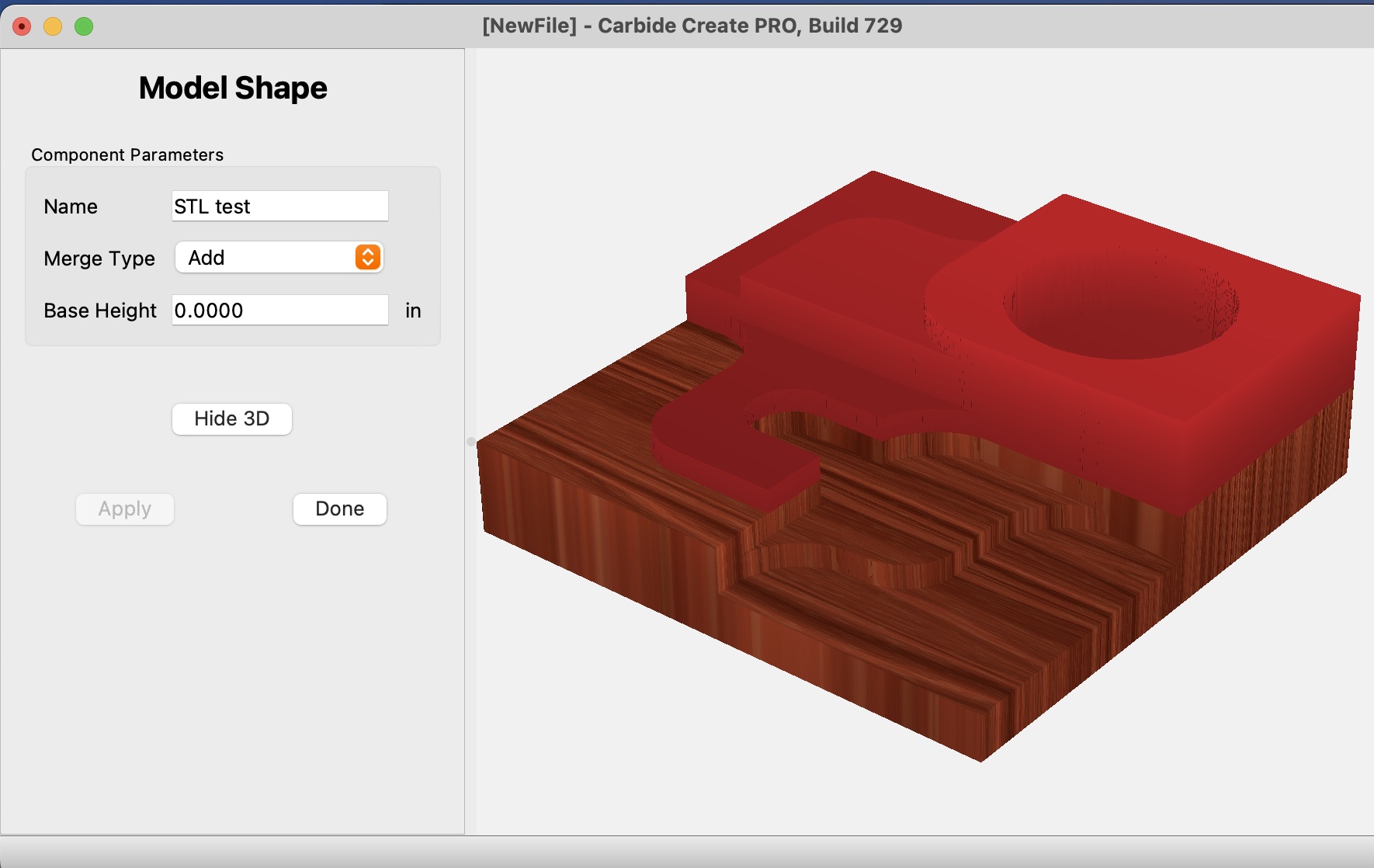
This is imported into CC, and given a height of 1" and and XY scale value of 1, so it should be imported at 1:1 scale. Based on the 3D view it seems correct, though for whatever reason, the top half is shown as though in error? Why?
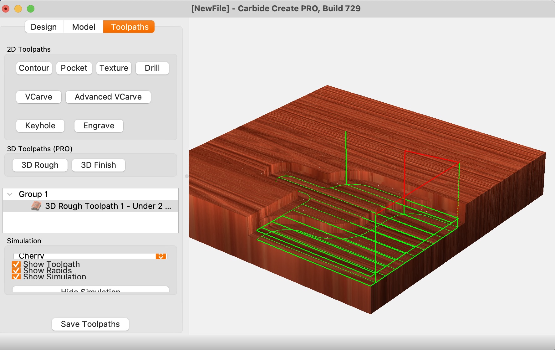
And then I draw a rectangle around the ‘component’ in order to create a toolpath. Using a rough 3D path, it will carve out some of the model, but why is only able to cut half of it?
I can understand in this example that this object could be created with only 2D toolpaths, but again, the point of the exercise is to see how accurate importing STL files can be, as importing full 3D models has many use cases.
I’d appreciate any insights that I’m missing.