Technical question. I’ve got a Pro 5–which has been brilliant. When using Fusion 360 to set up a milling project, I typically set the Stock Point (the reference point for the work coordinate system) to the TOP of the stock at the left-most, front-most corner. A top-down view would show this as lower-left corner, but with the bit zeroed on the top of the stock. I think this is what everyone does, since it’s what all of the tutorials show.
My question: is there any reason I can’t set the Stock Point to the bottom of the stock? The coordinate system would then be zeroed effectively on my surface board. It wouldn’t change the tool paths, since those would be calculated the same, but it would ensure that my end mill cut as close to the surface as possible (when cutting profiles out of the stock).
Hope that makes sense. I realize that this would introduce another problem—namely, how to zero the bit to a corner of stock blocked by the stock itself. But I’m confident I can work around that.
I tend to always set my WCS origin on top, but on through cuts, I use my wasteboard as a reference. Let’s say I’m cutting a piece that’s 24mm thick, I just jog to the bottom of my stock and set that location as Z-24. G10L20Z-24
This became a habit years ago, and it keeps me from screwing up and mixing up my WCS and also allows me to use less Setups in my CAM.
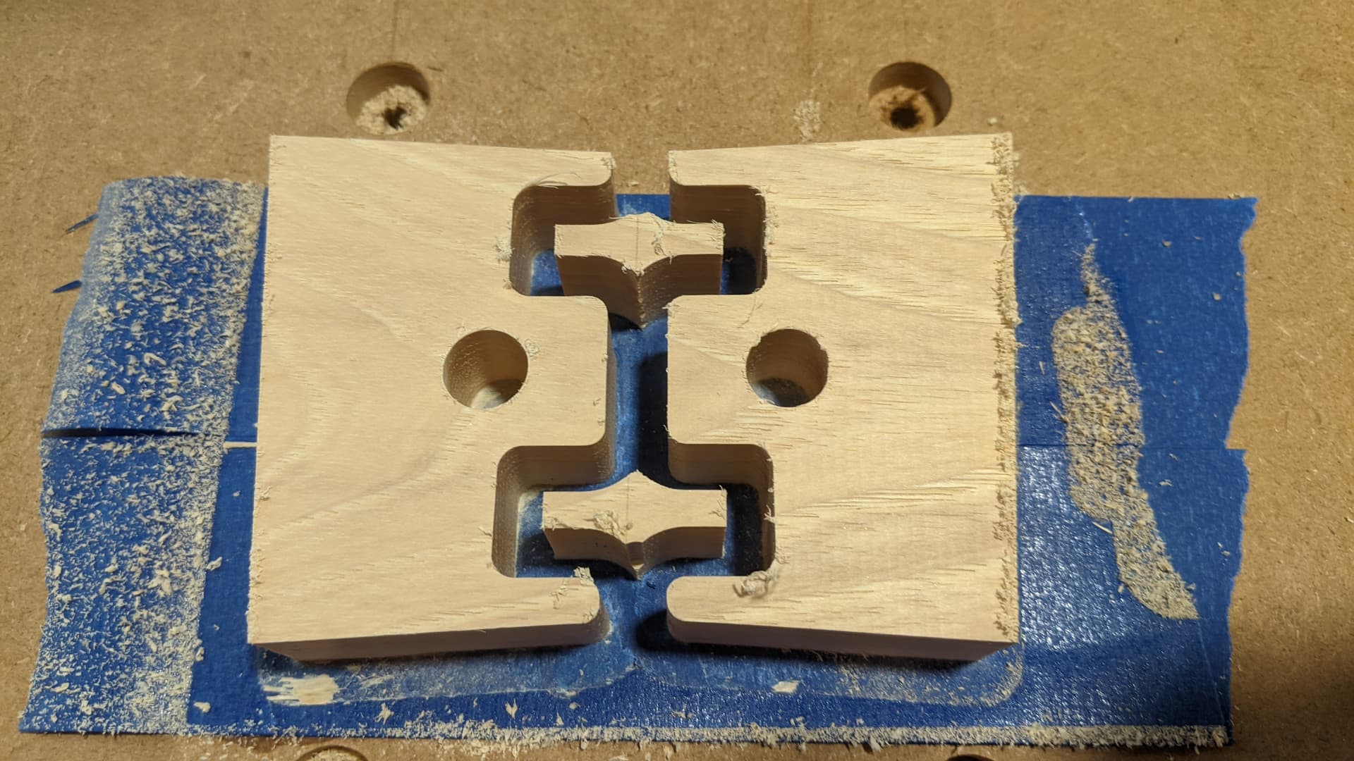
I’ve said this before…I measure the success of a cut by how close I get to cutting only one layer of blue tape.
If you have not used painters tape and super glue you apply painters tape to the spoilboard and another layer on the back of the project. Then the super glue in between. When the project is complete you use a putty knife to pry the tape off the spoilboard and remove your project. If you material is very thin just be careful you dont break your material with the putty knife.
I use the stock bottom in fusion almost exclusively. It helps to save the spoil board.
To set x,y zero I use the bit zero and just run an x and y probe using stock top. This leaves the z zero alone. I pretty much set the z zero height once and do not touch it. The machine seems to keep this z zero through power cycles very well.
When I use double sided tape, I just add an offset to the stock bottom layer on each toolpath.