WillAdams
February 1, 2025, 7:44pm
1
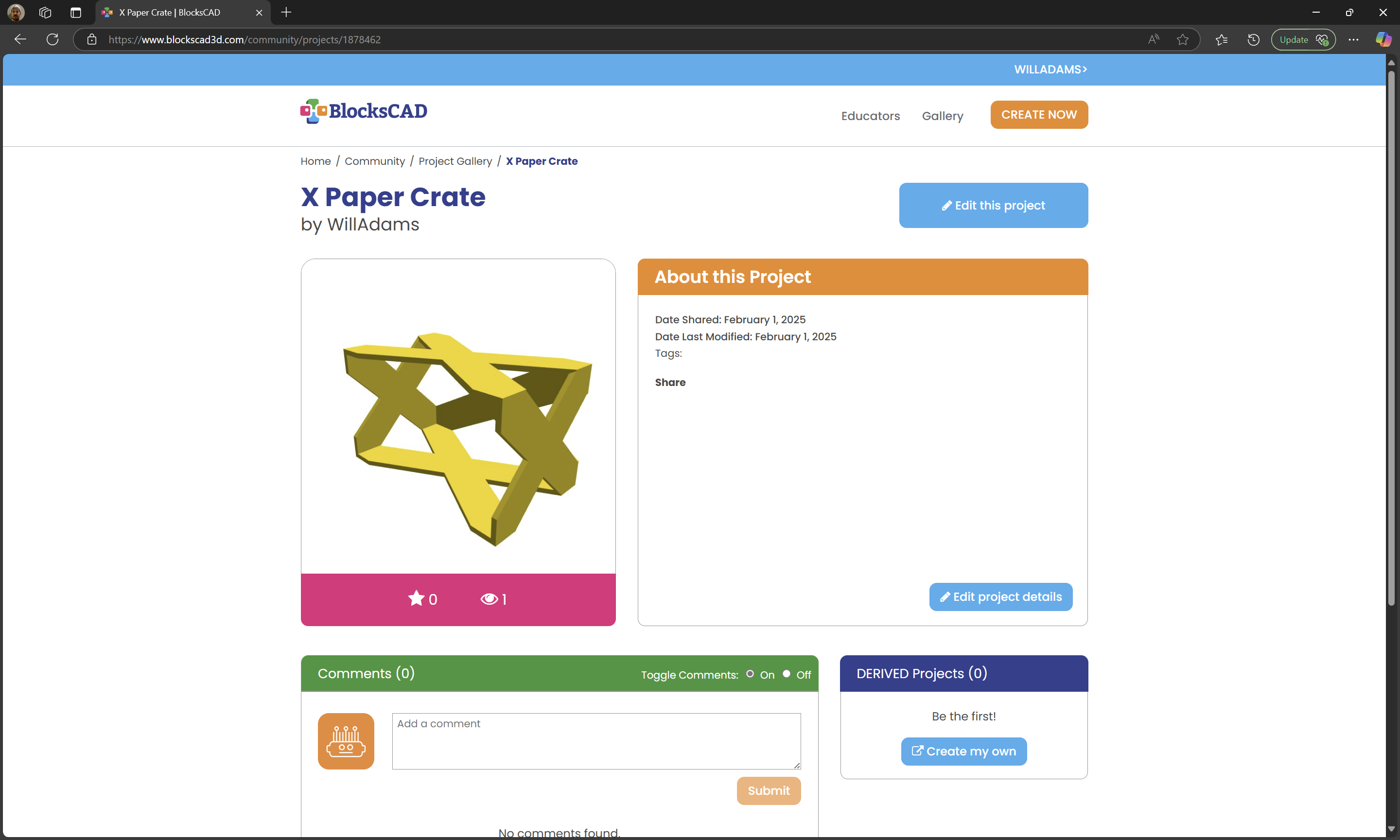
Needed to work up a design to store various hobby stuff — I usually use paper boxes, since they are reasonably sturdy and free, but wanted something which was efficient in terms of materials.
After a bit of thinking, came up with:
which is available at:
https://www.blockscad3d.com/community/projects/1878462
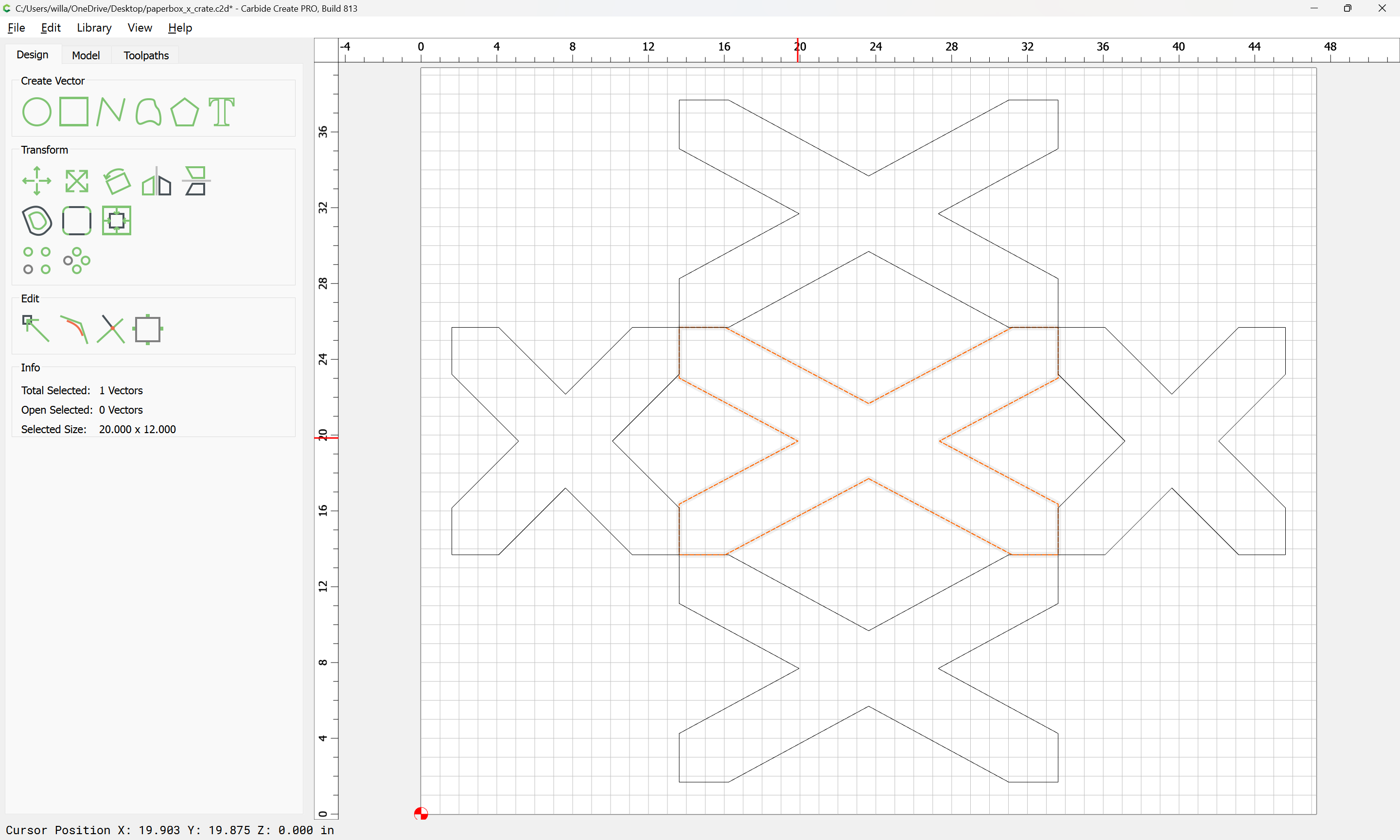
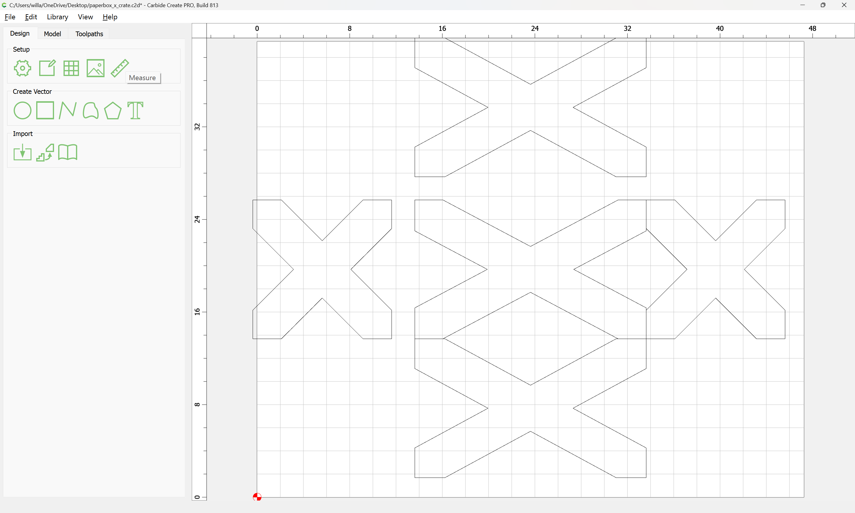
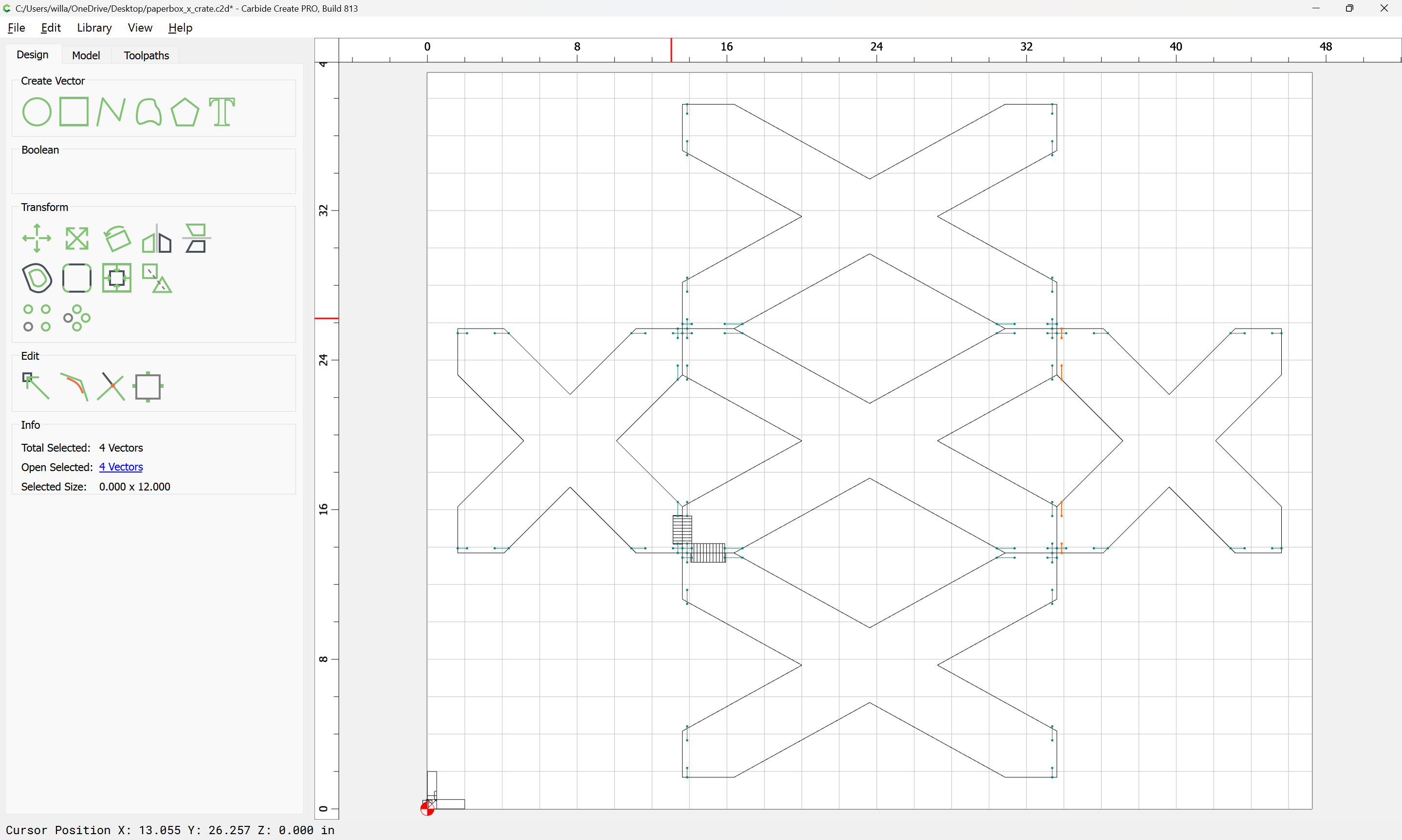
After loading the OpenSCAD code and adding a projection() command to allow exporting a DXF and scaling things up we get:
which is pretty close to what is wanted, but needs a bit of adjustment — rather than work out a trigonometric solution, we will take a few measurements, draw up some boards and iterate until things fit as desired…
WillAdams
February 1, 2025, 8:09pm
2
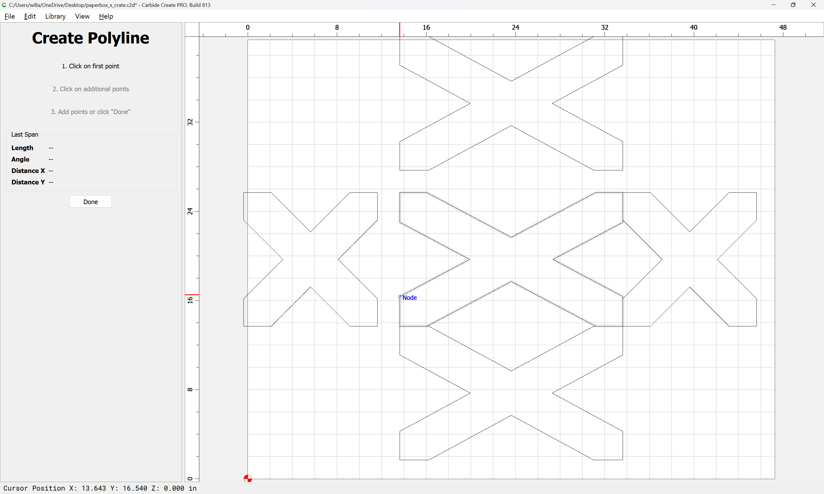
First, we measure the angle:
27.964 degrees
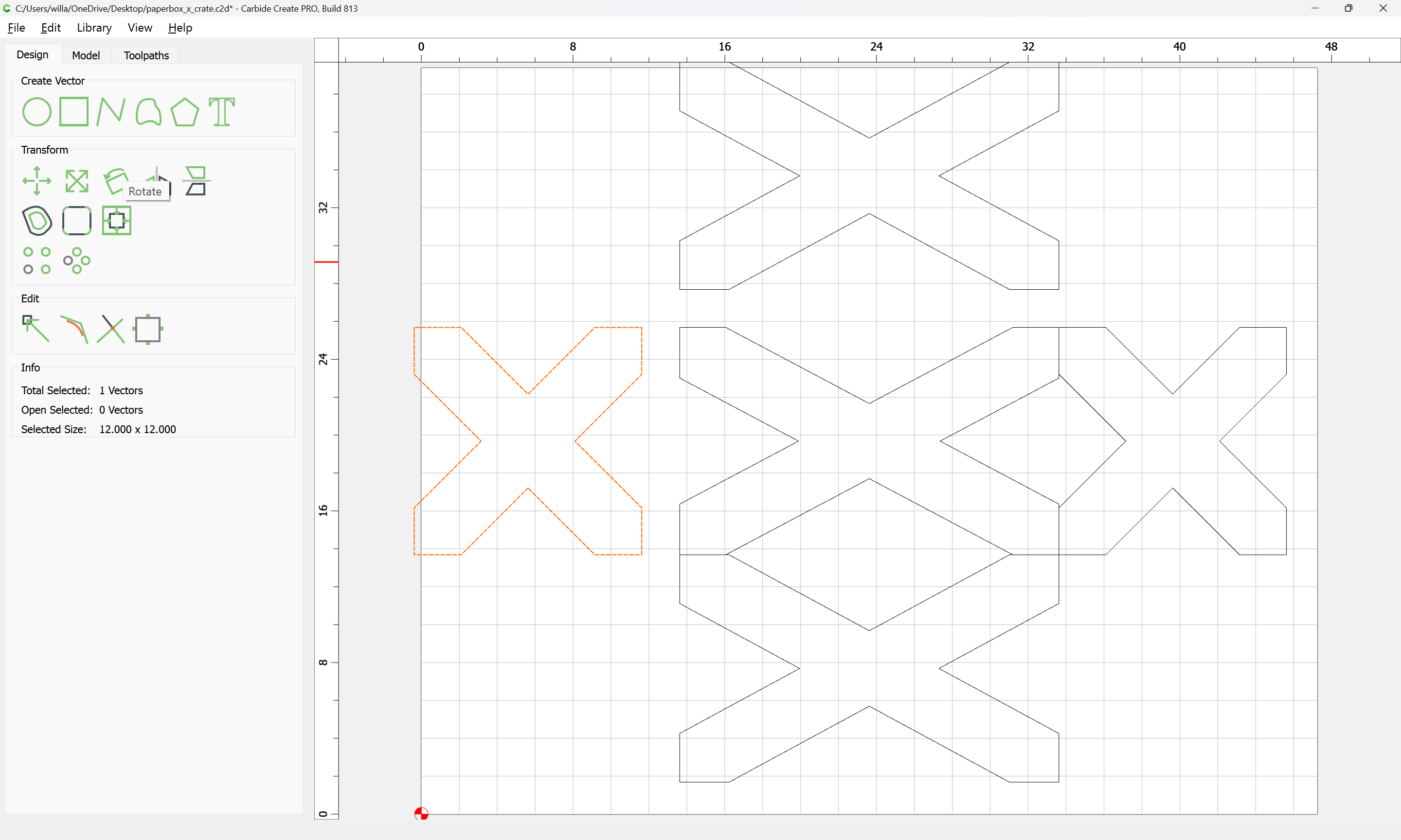
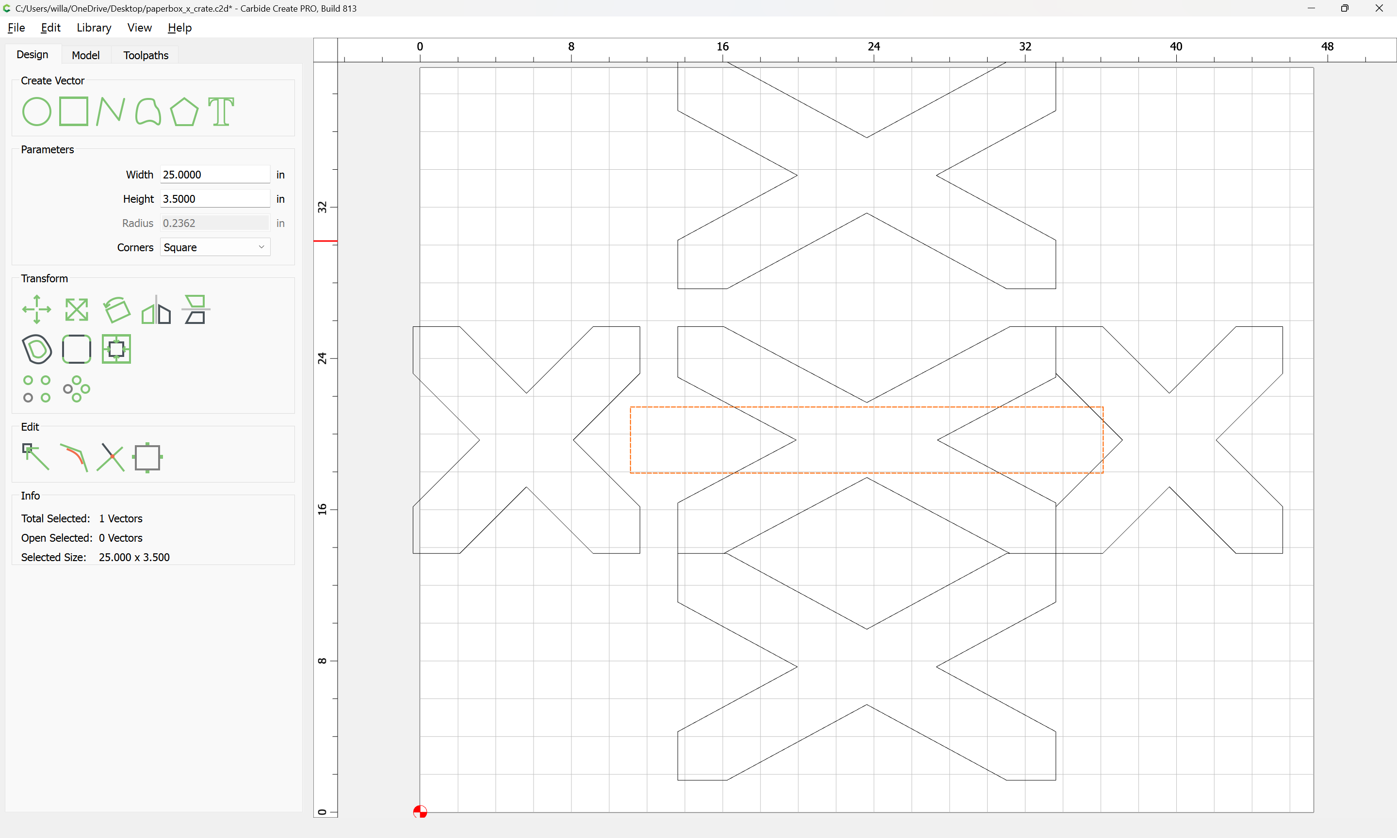
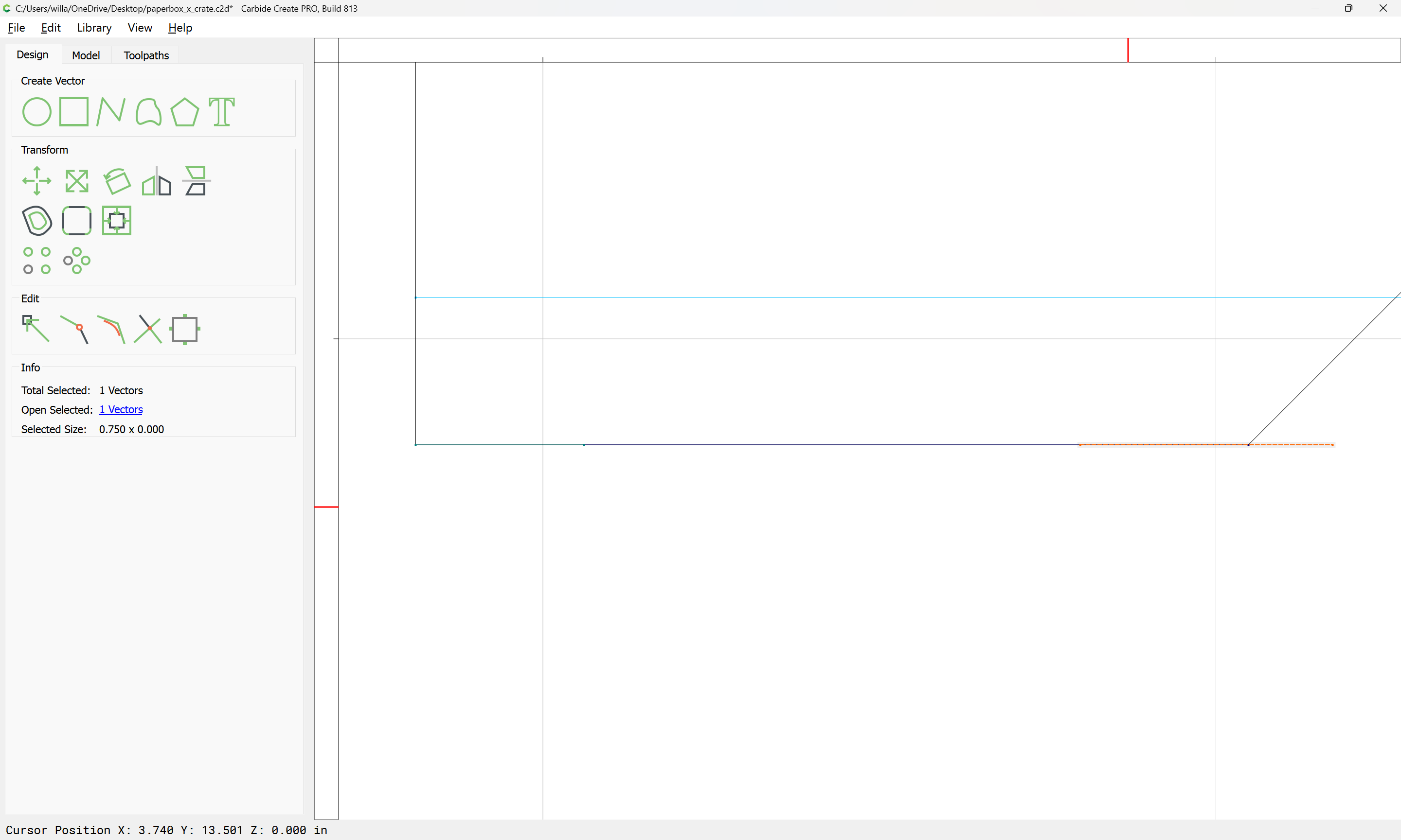
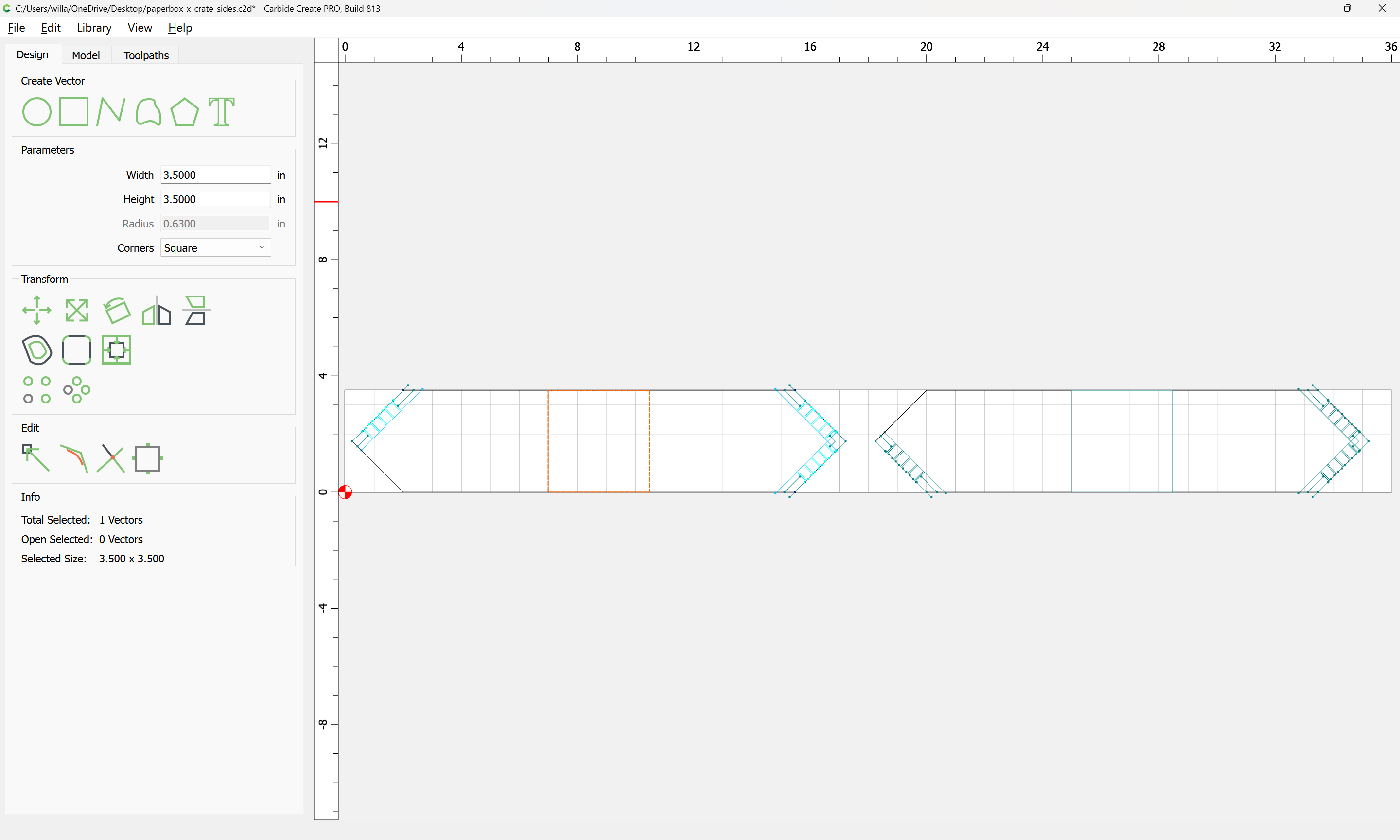
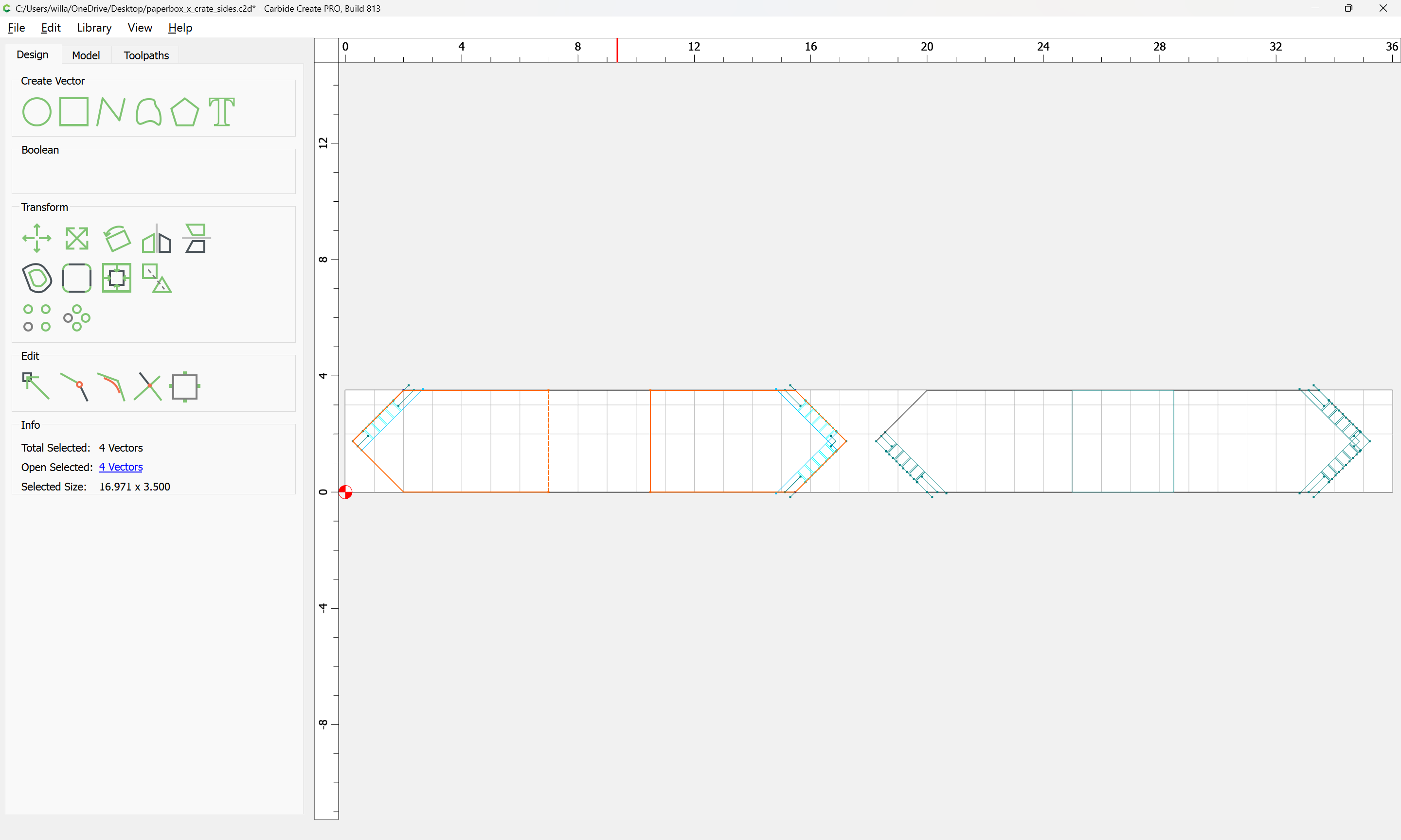
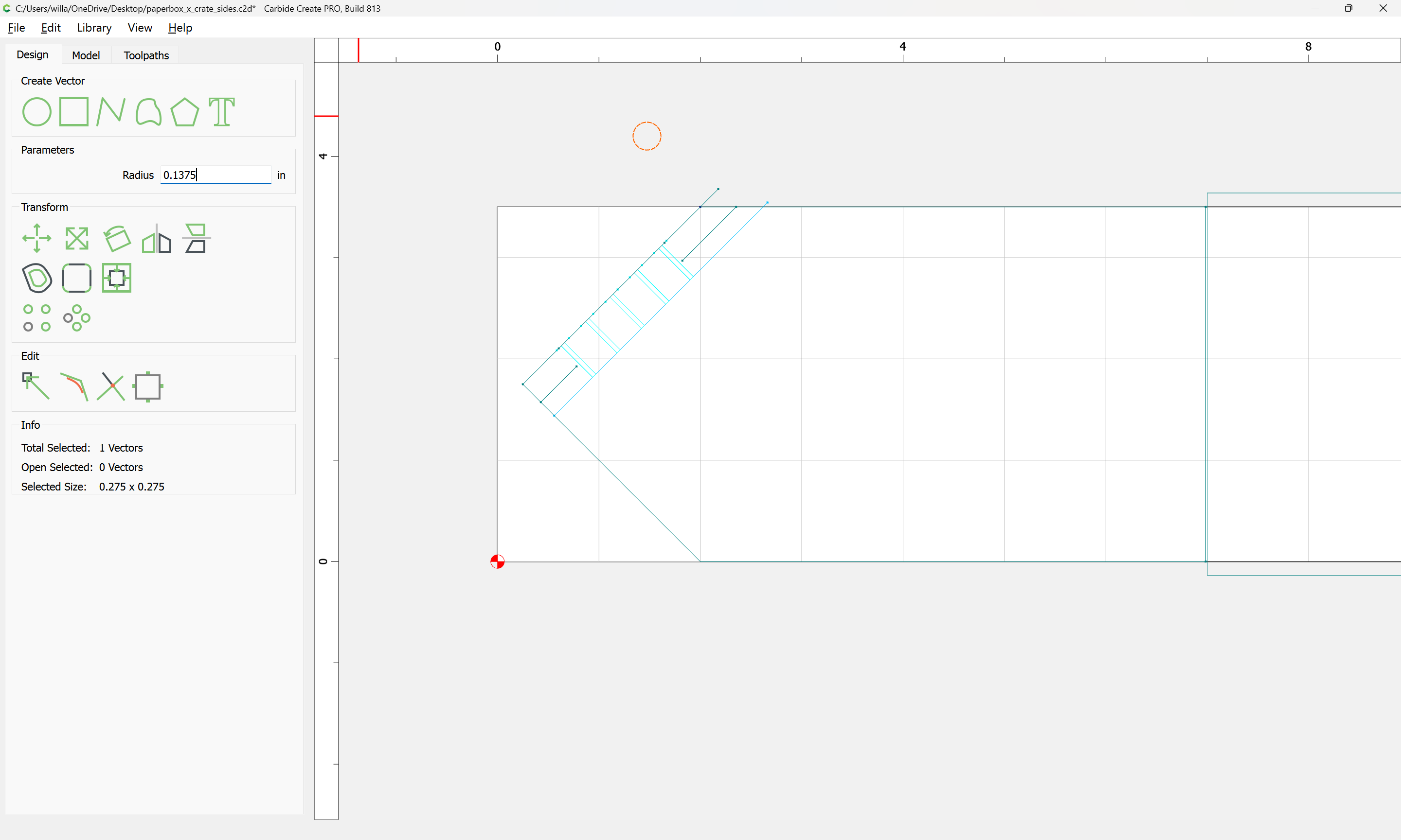
Next, we need a board — since the ends are square:
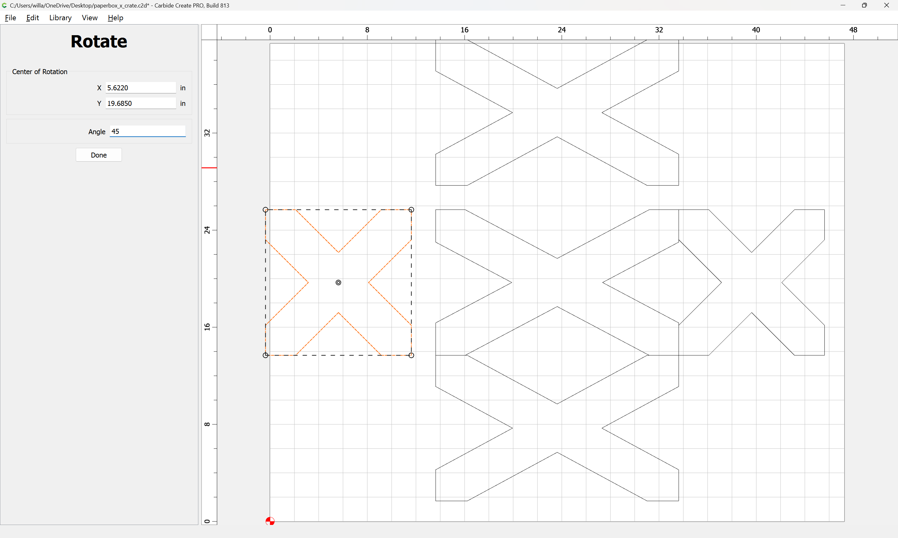
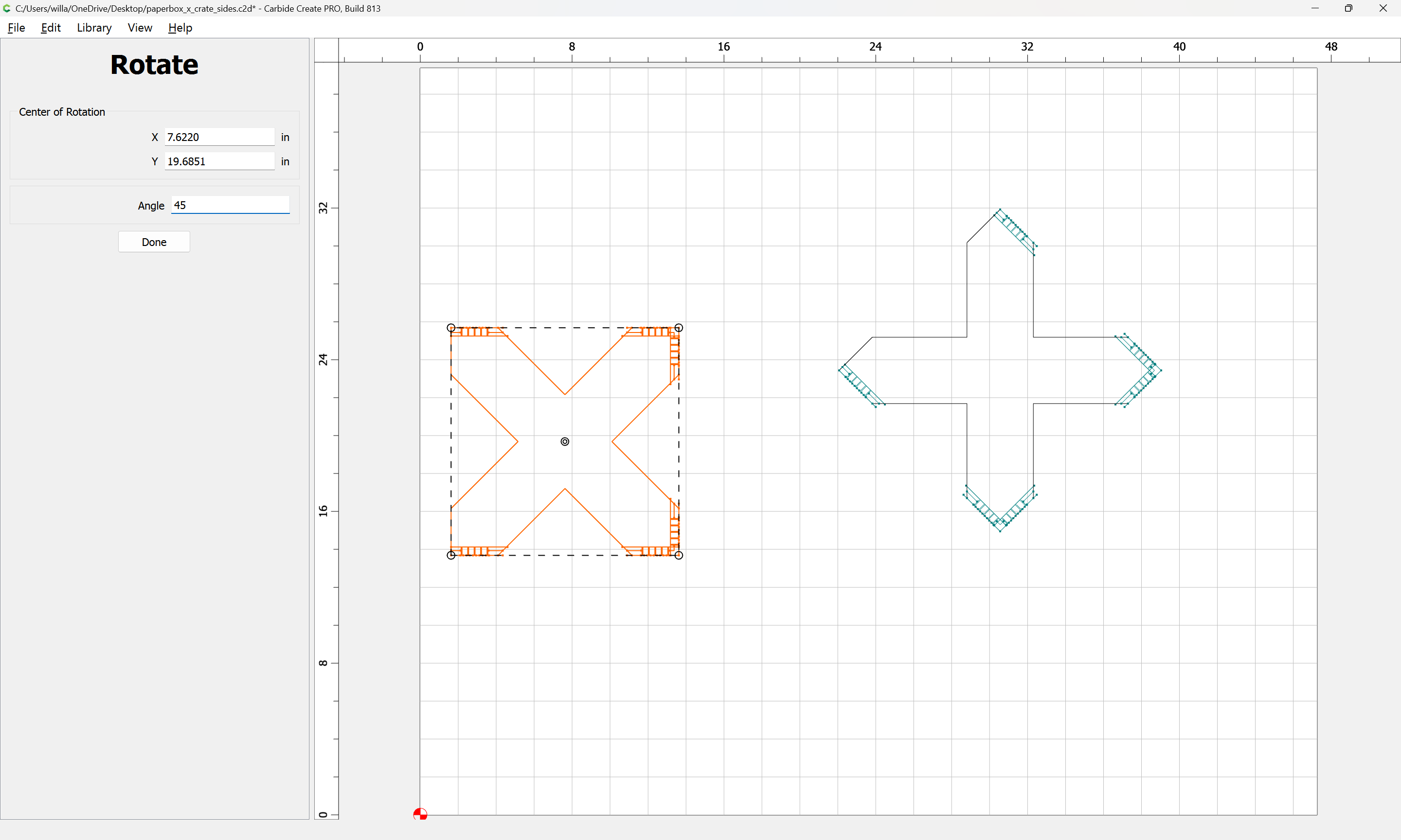
We can rotate them 45 degrees to get the designed board width:
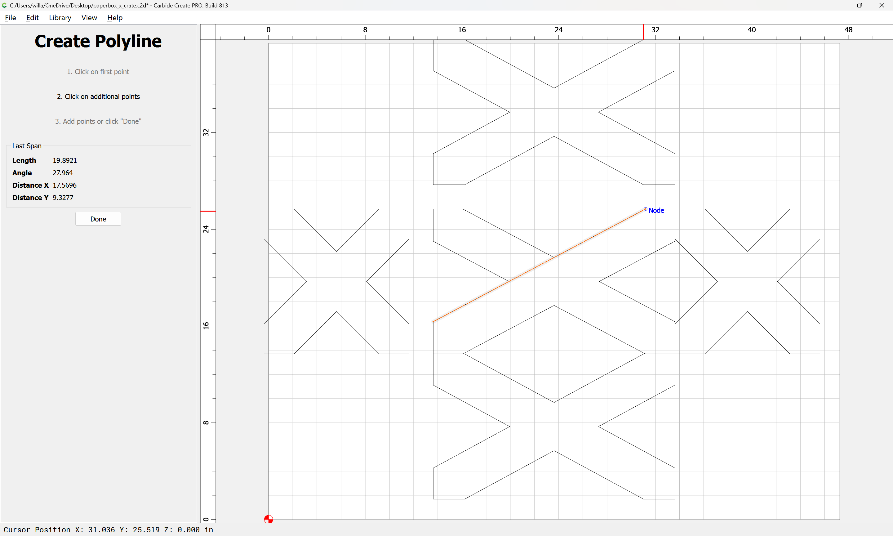
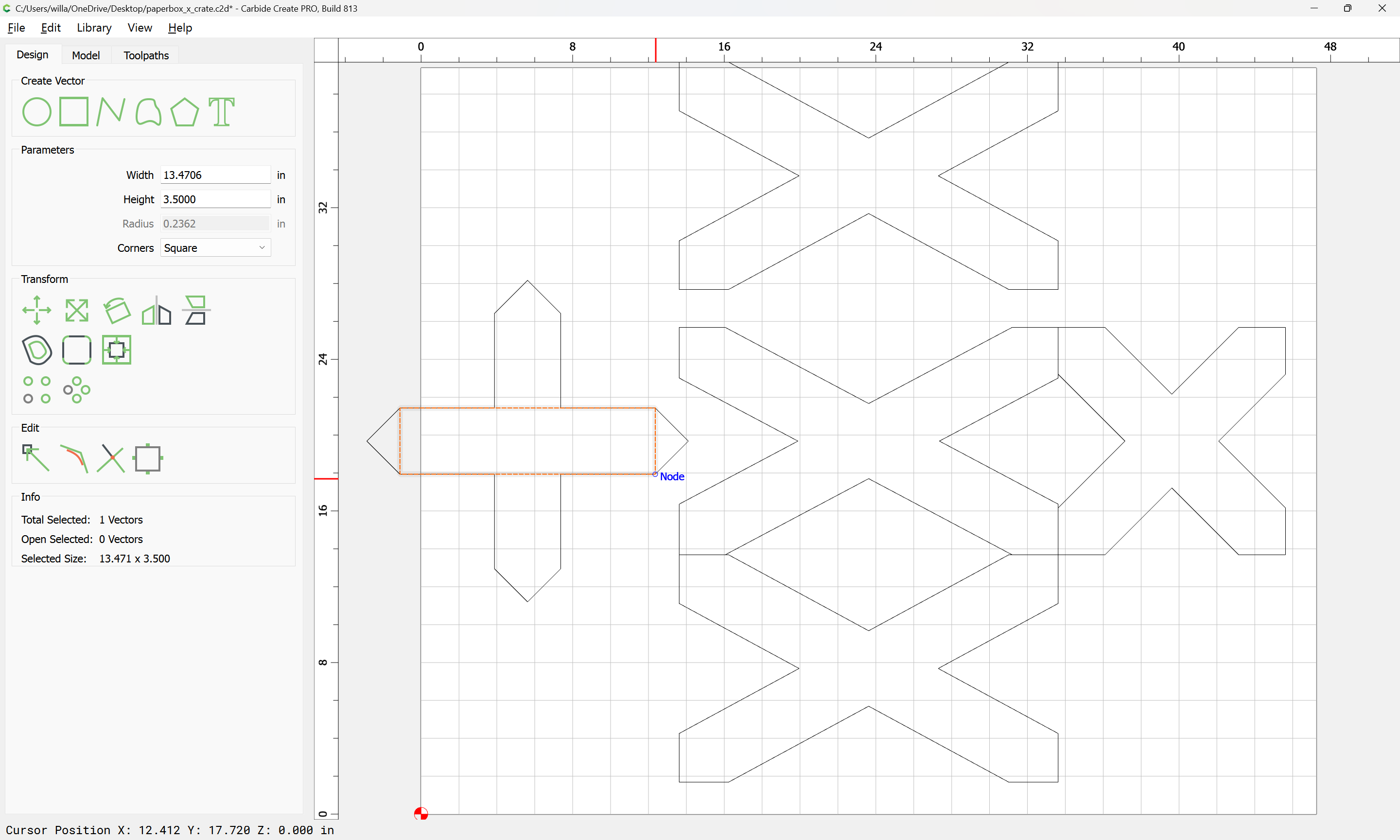
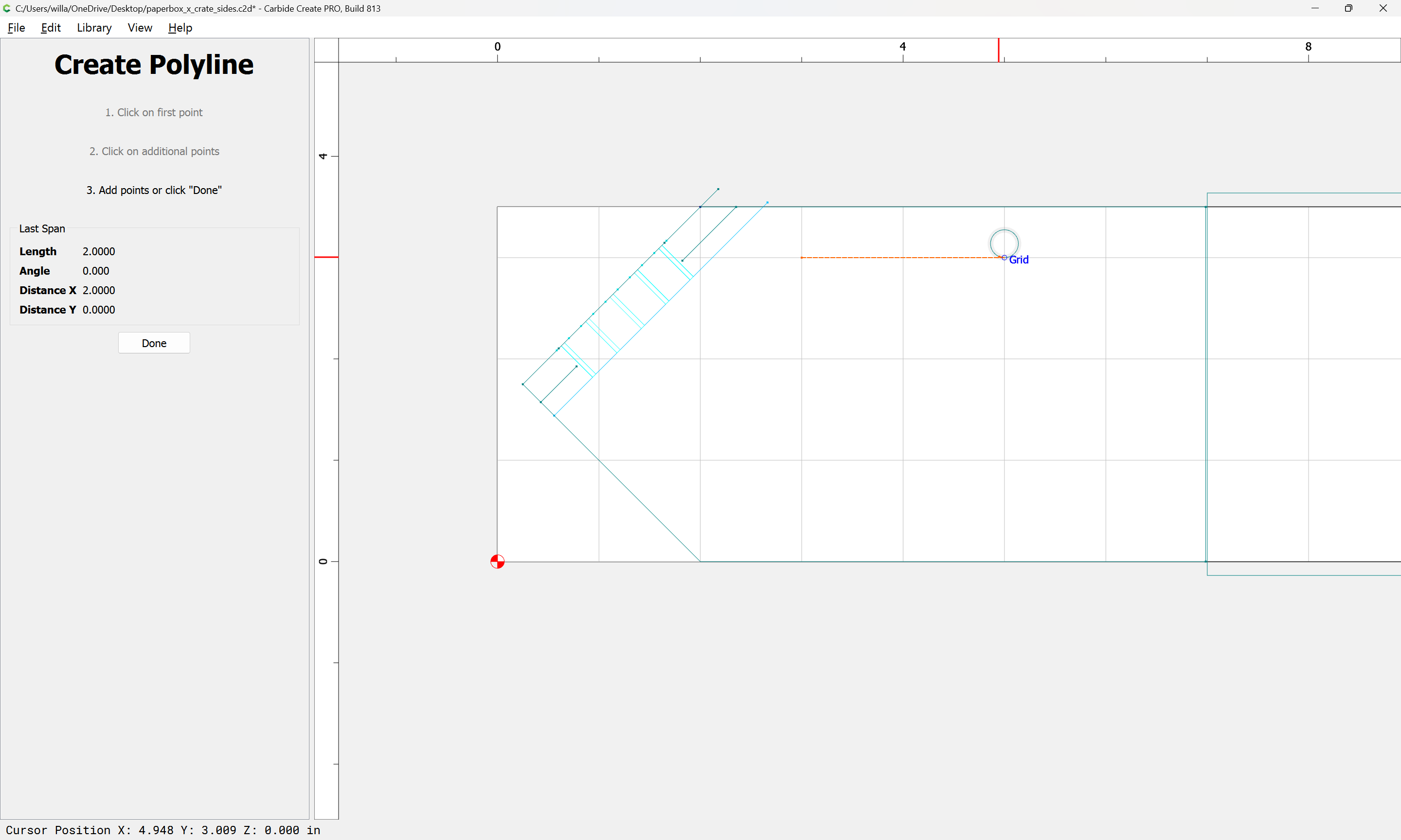
We can then lengthen the board:
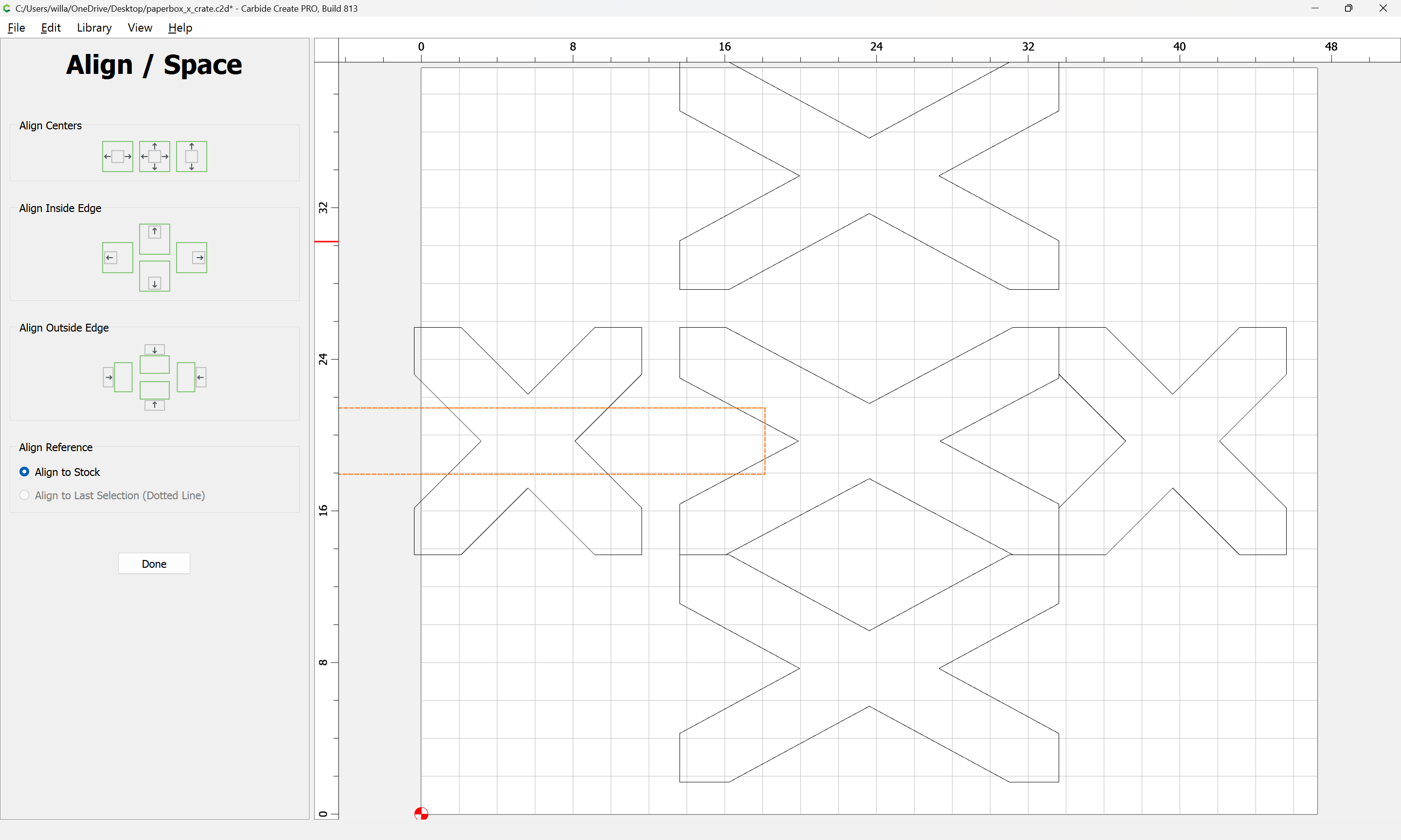
and align it to the center of the stock:
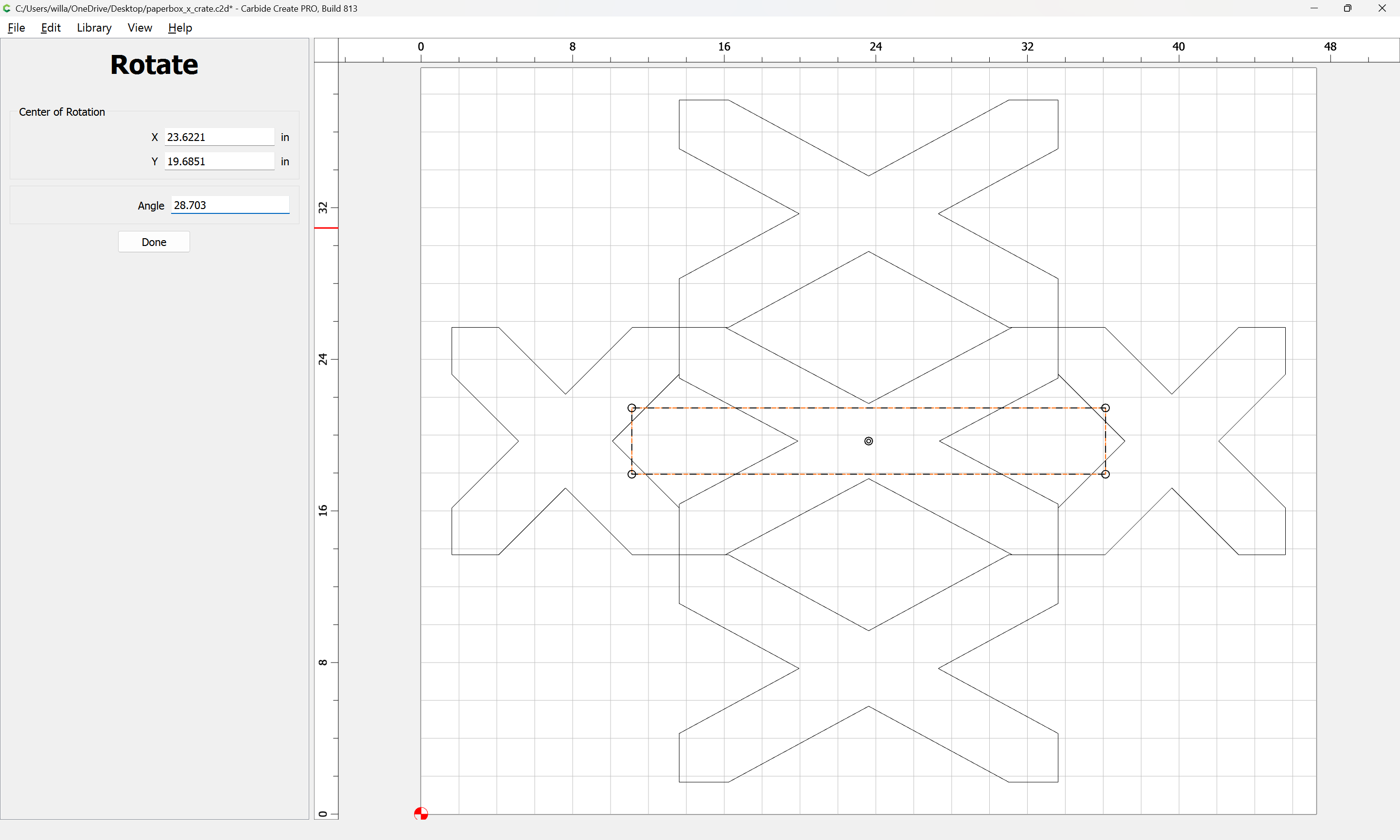
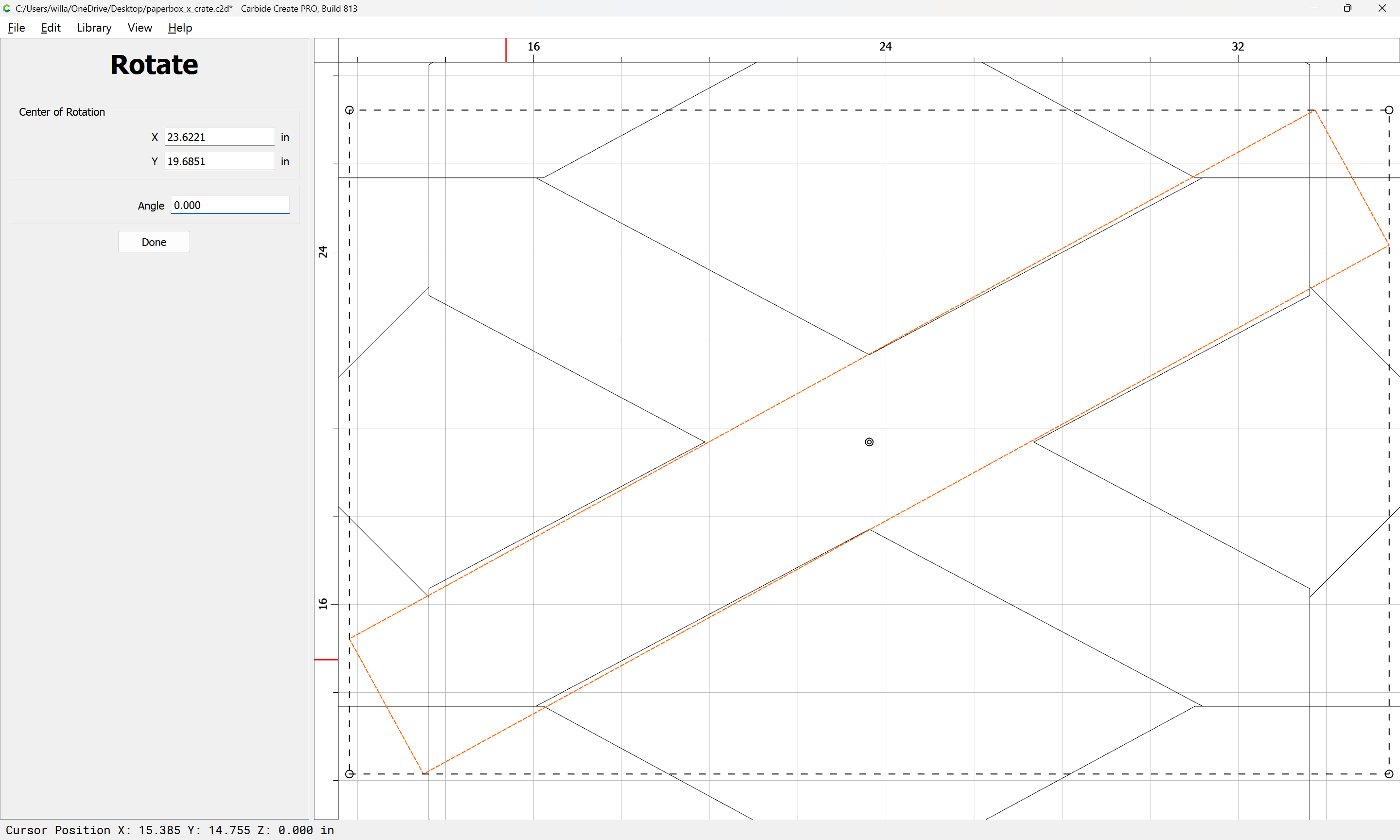
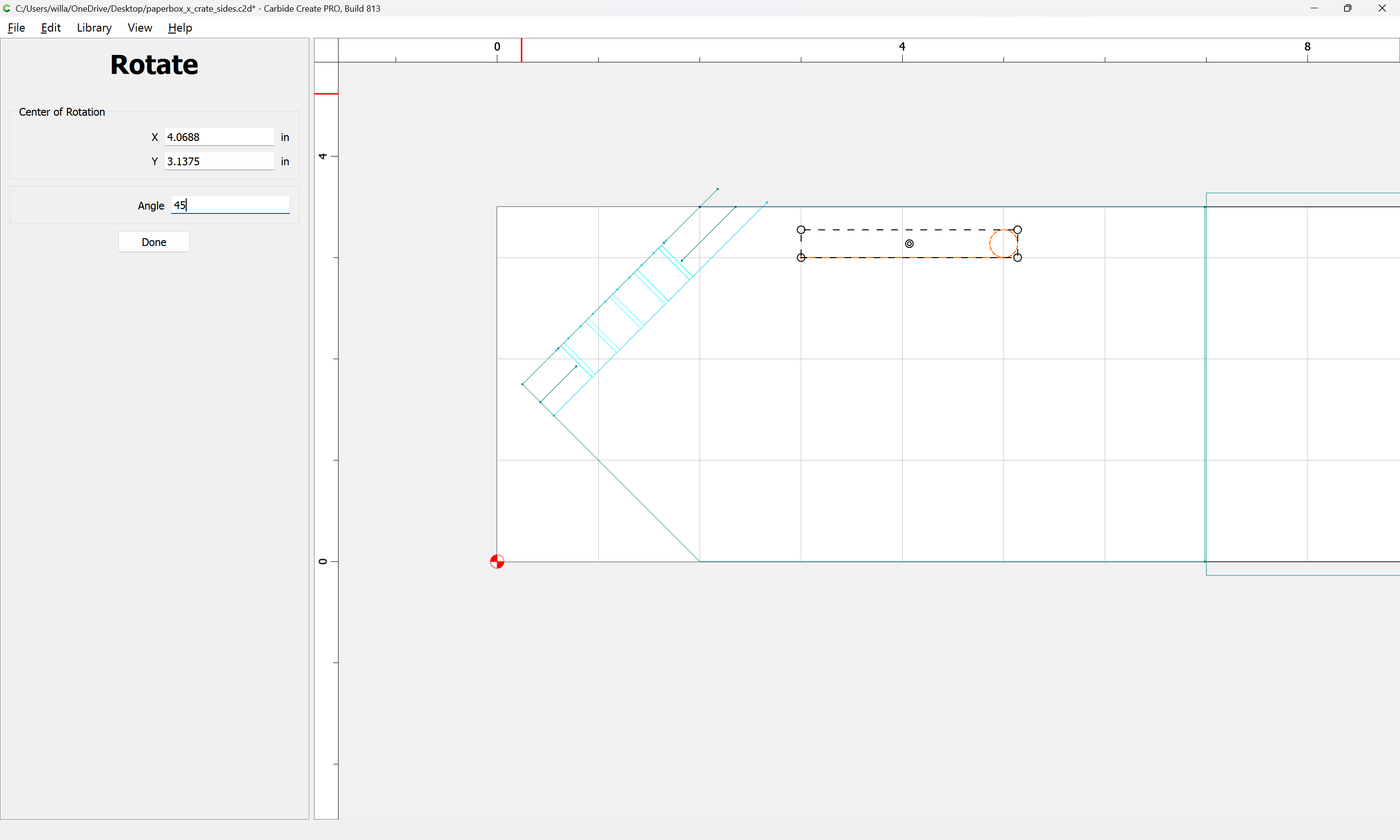
and rotate it.
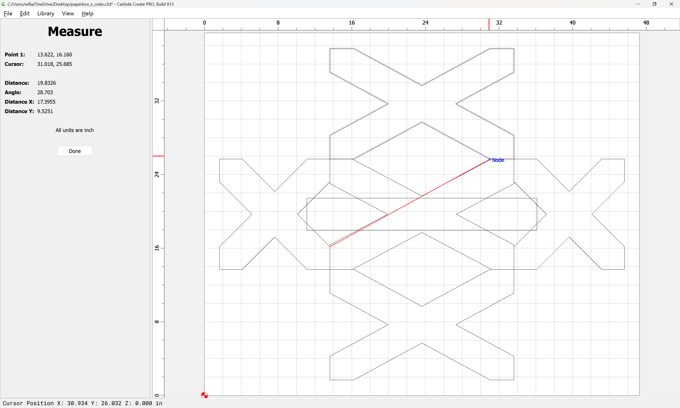
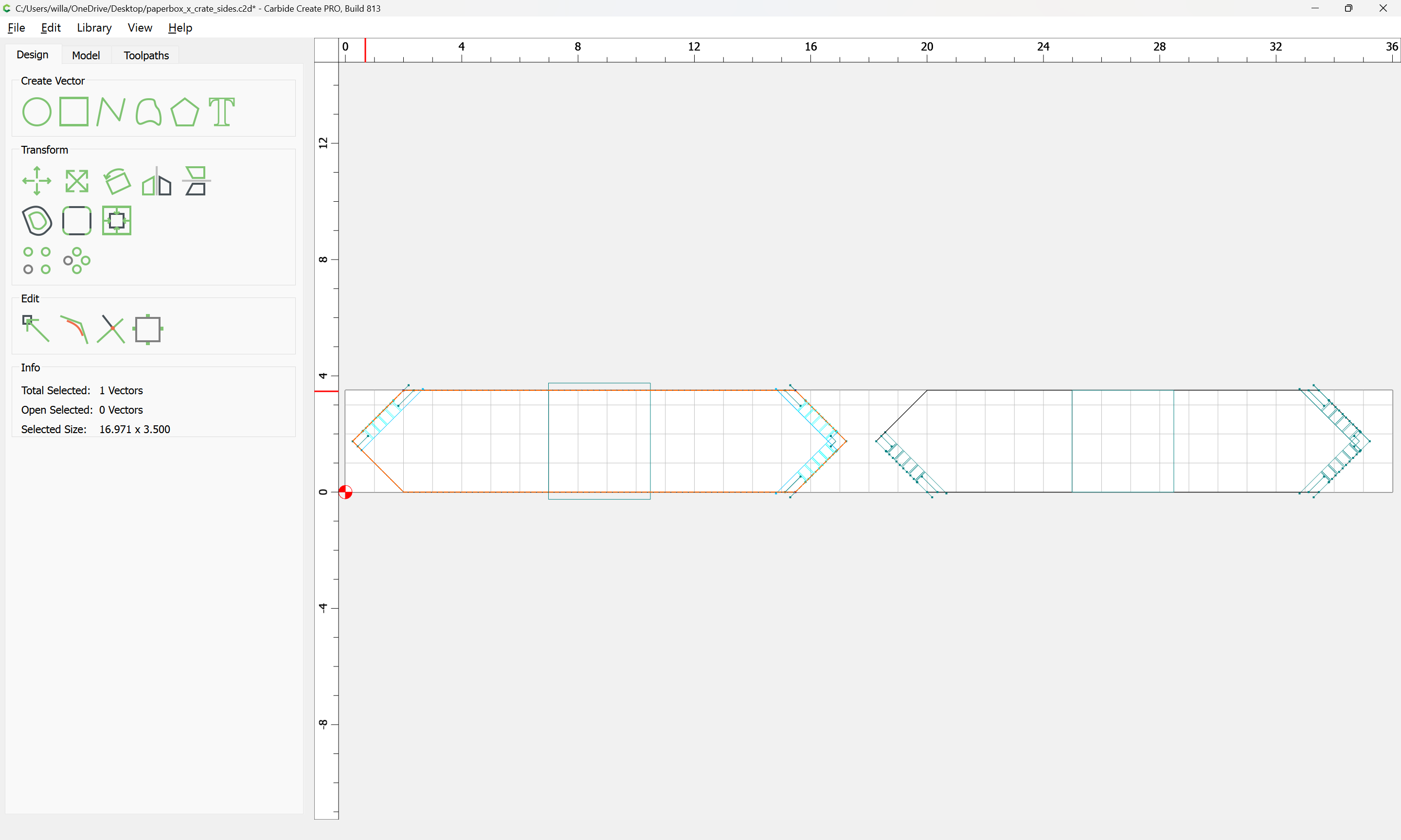
Putting things back together, a quick measurement:
suggests 28.703 degrees as the correct rotation (actually, 28.918 seems a better fit):
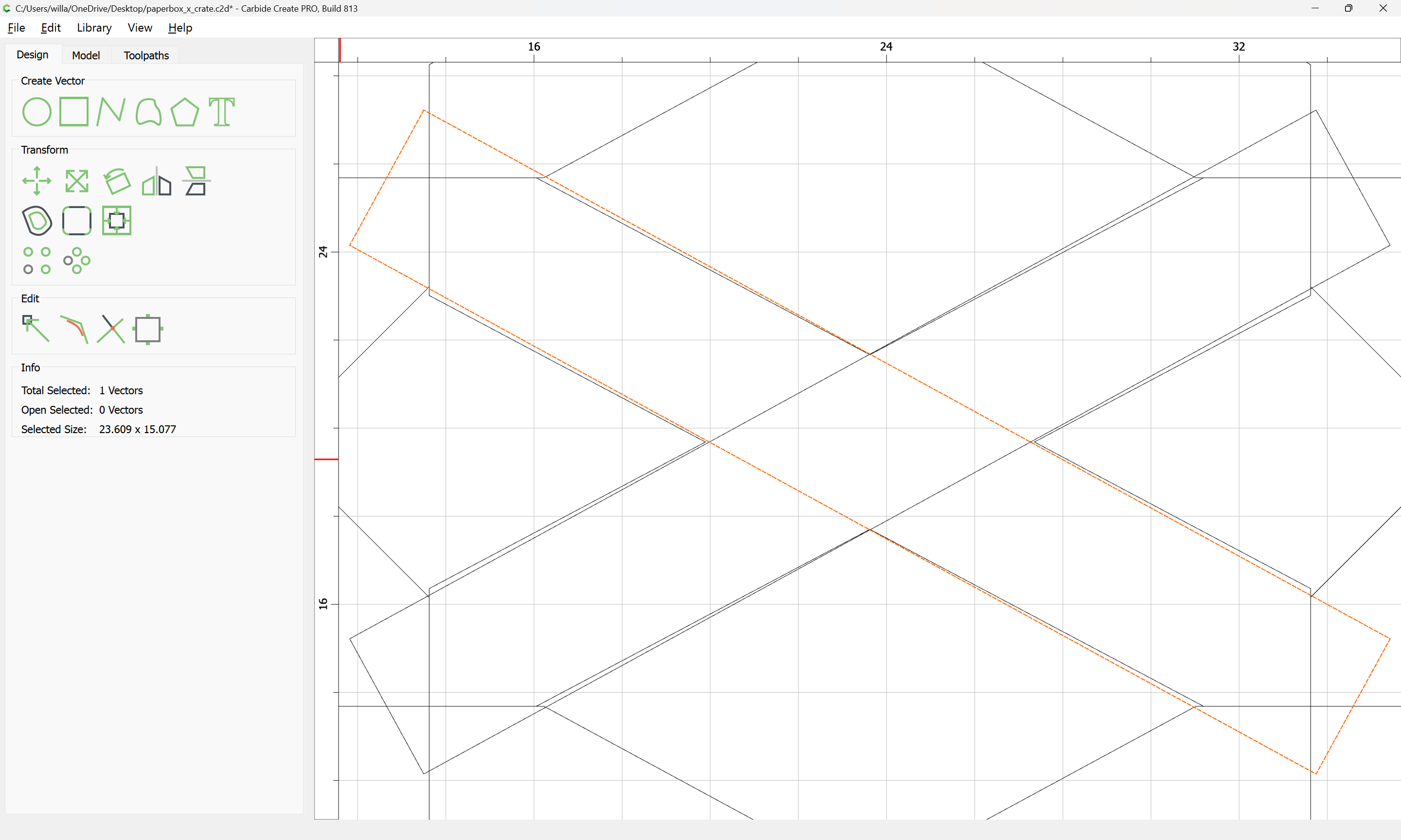
which looks to match up well:
Done.
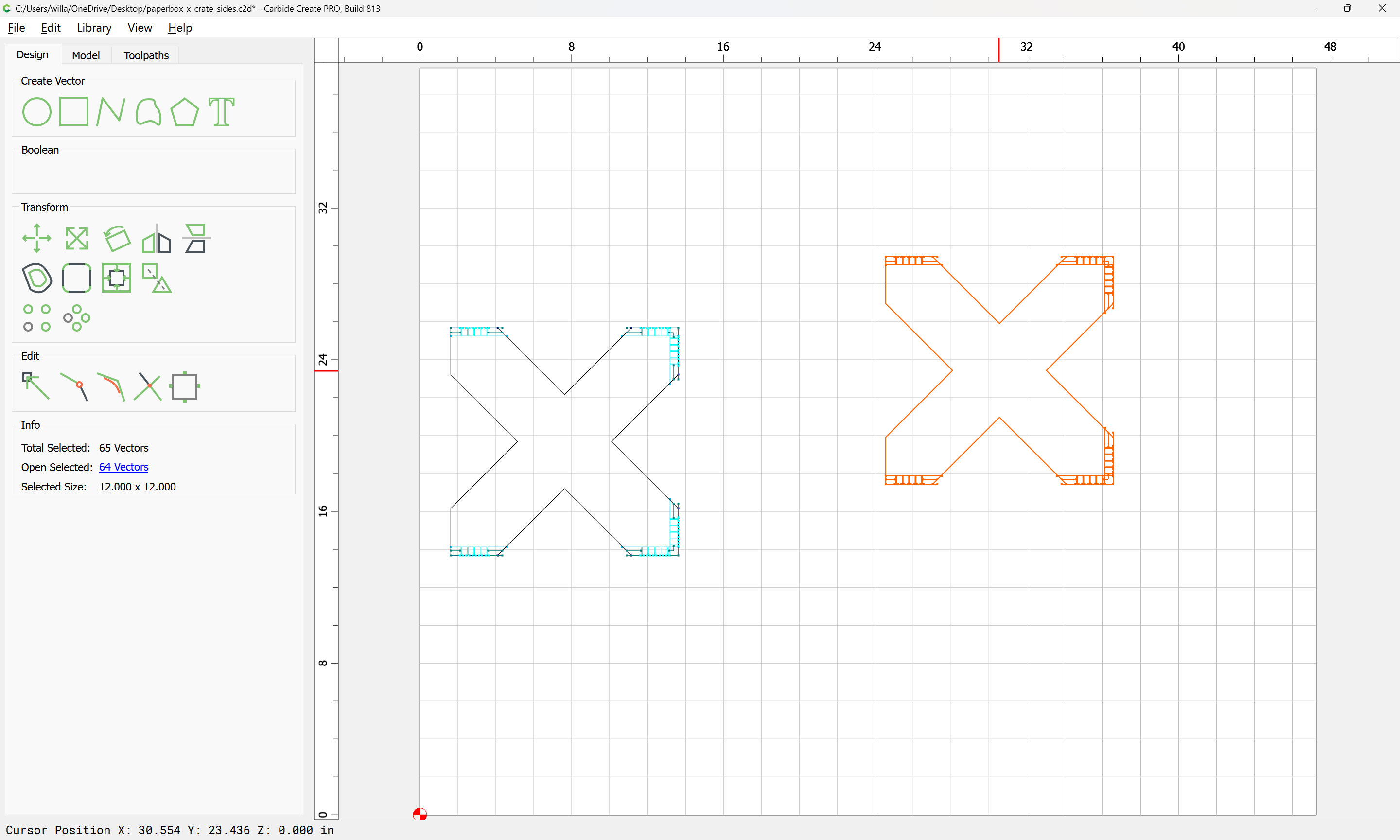
Copy, paste and flip to arrive at:
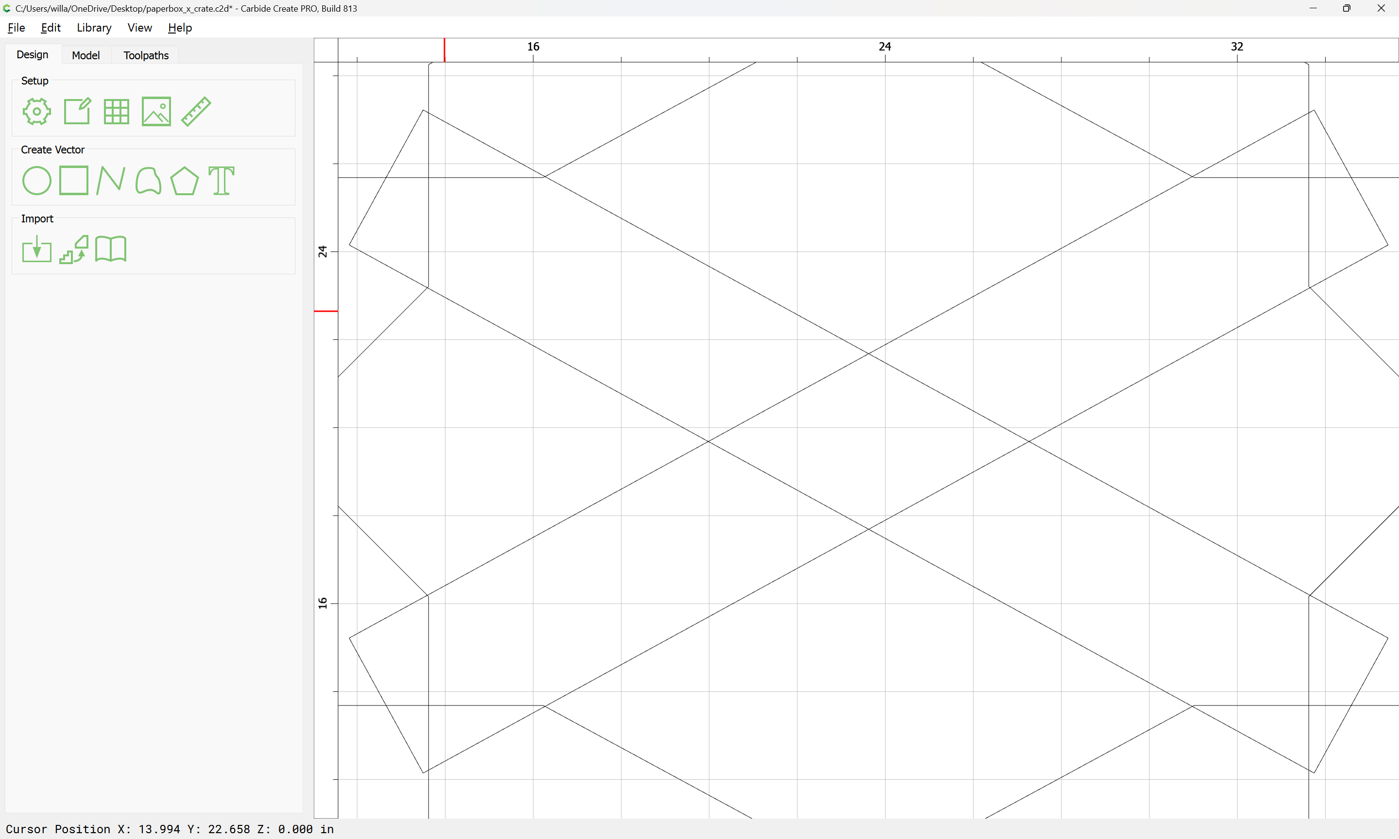
Delete the underlying original part:
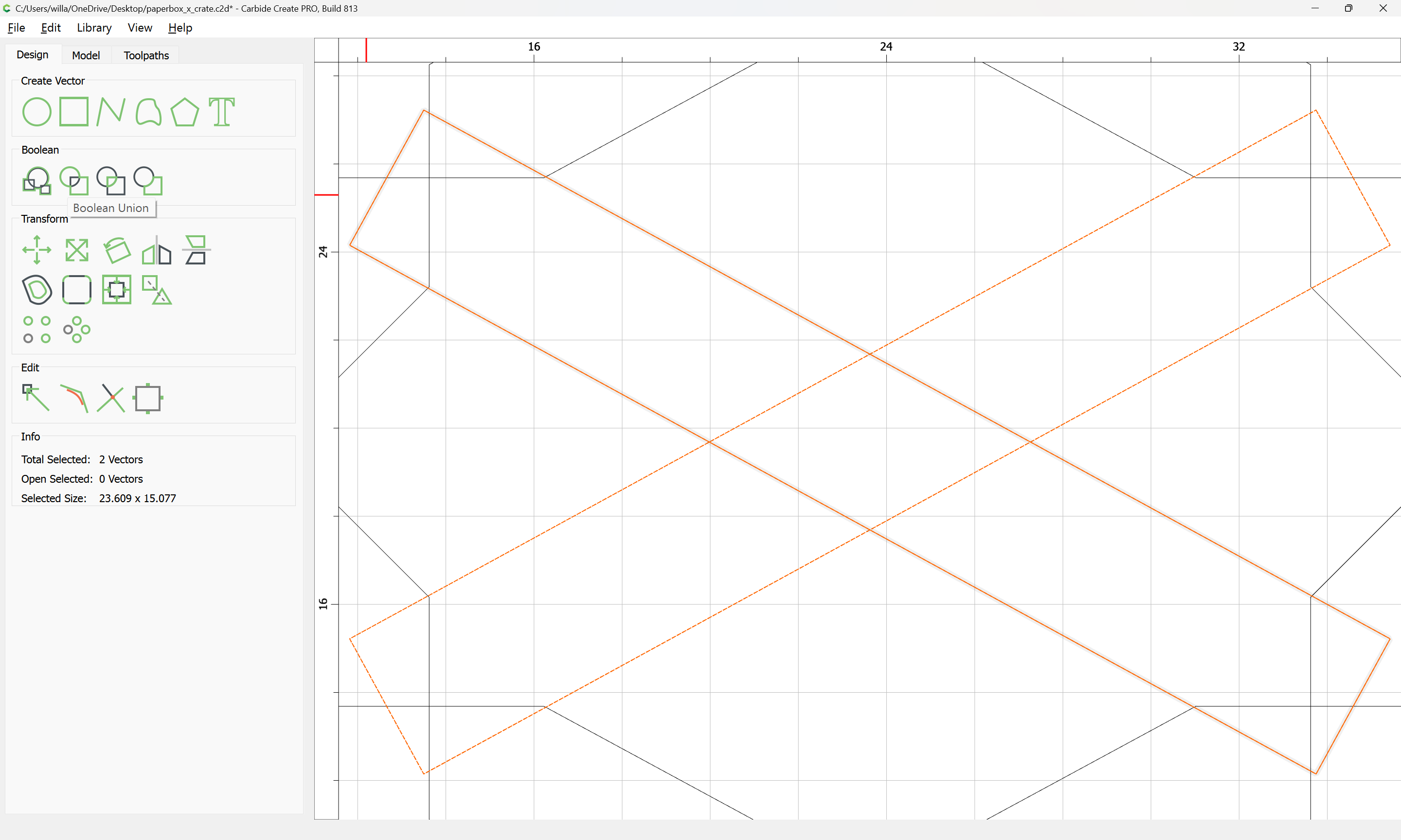
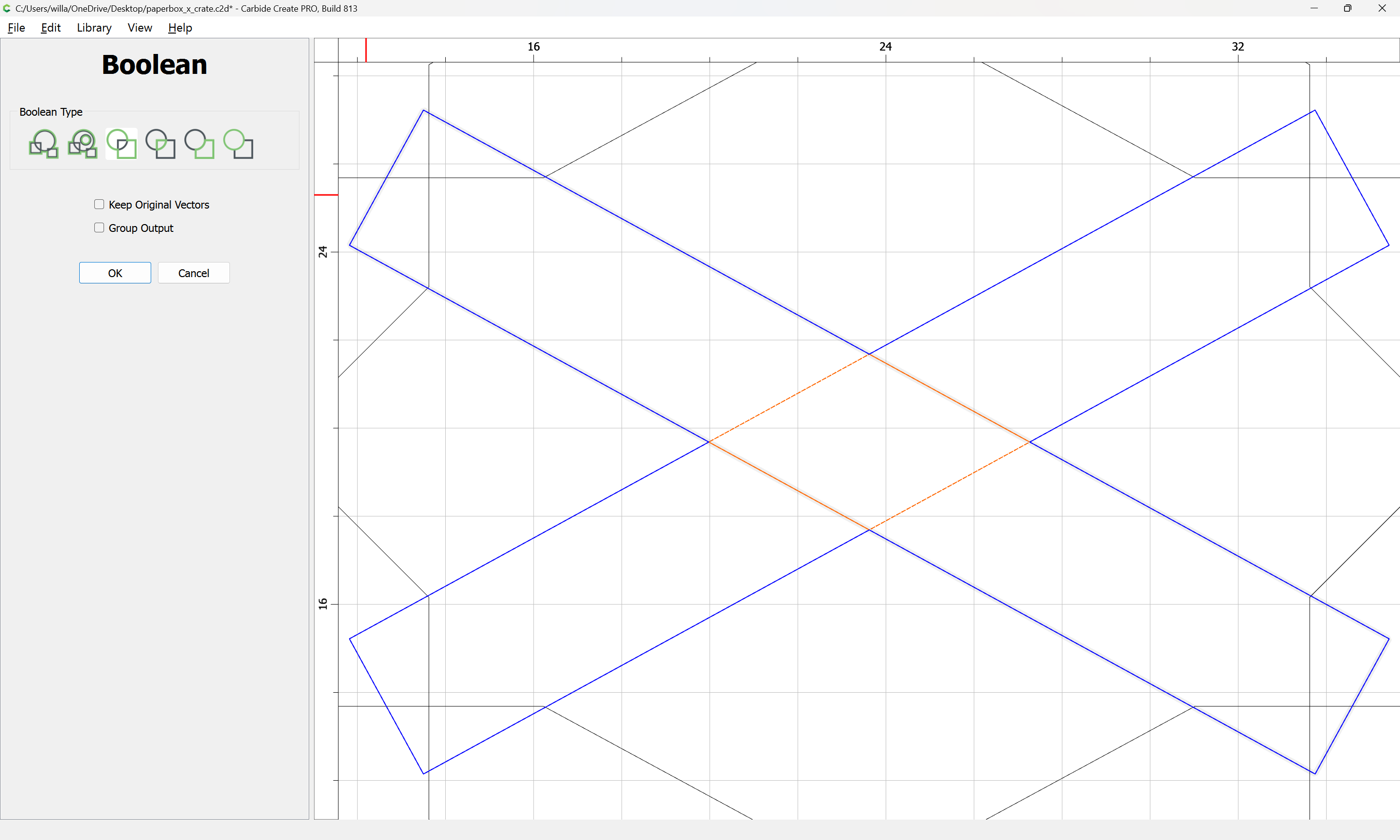
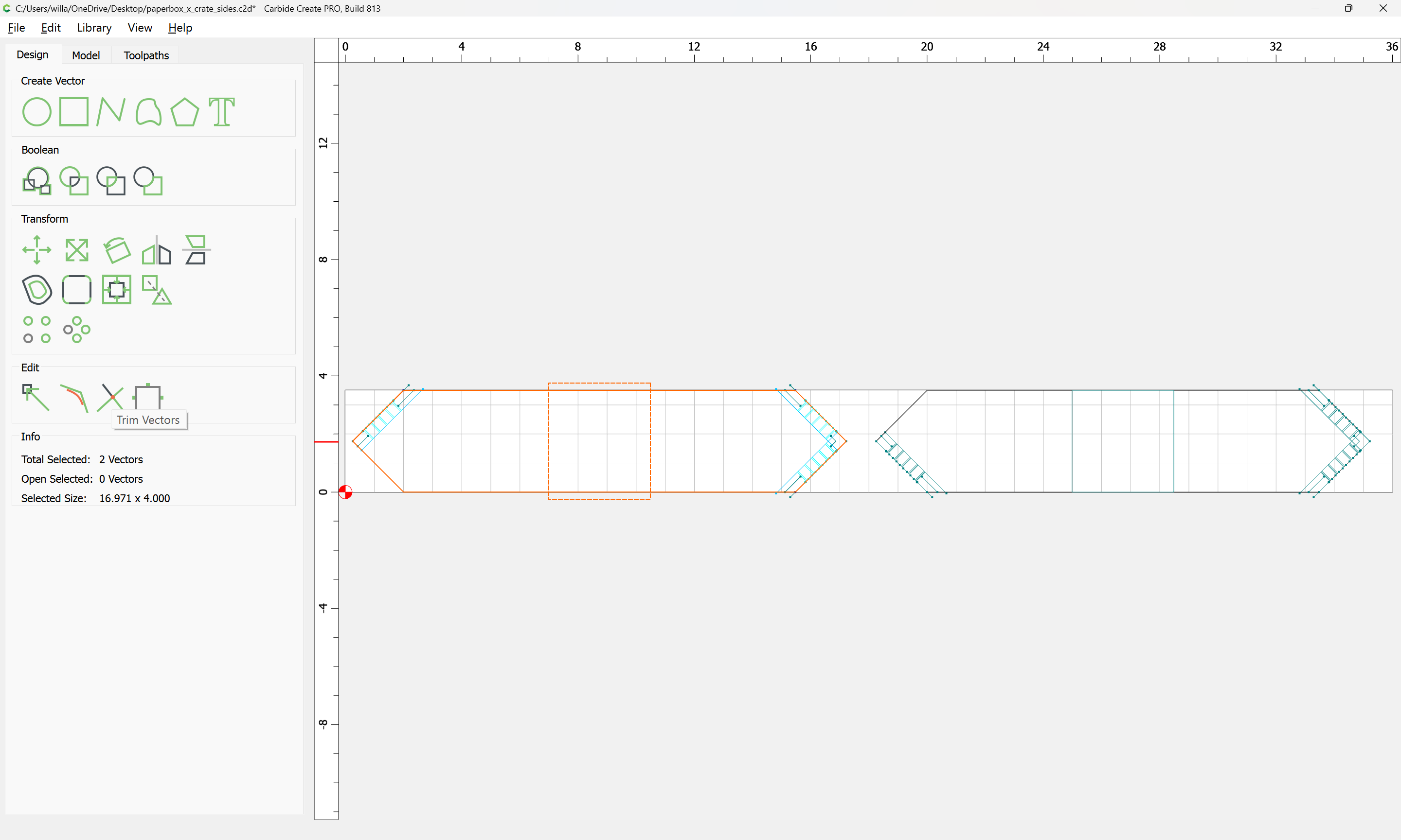
Select and Boolean Union:
OK
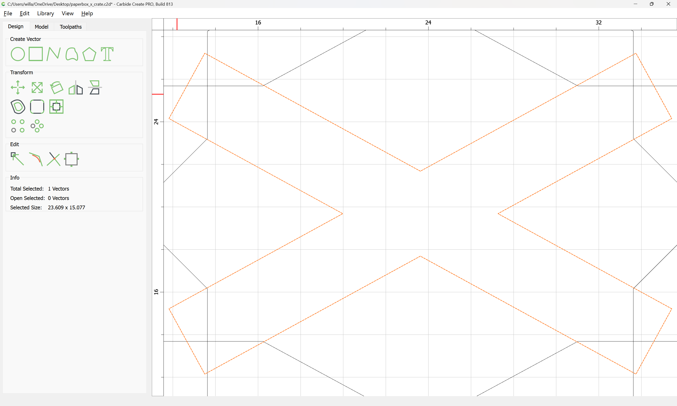
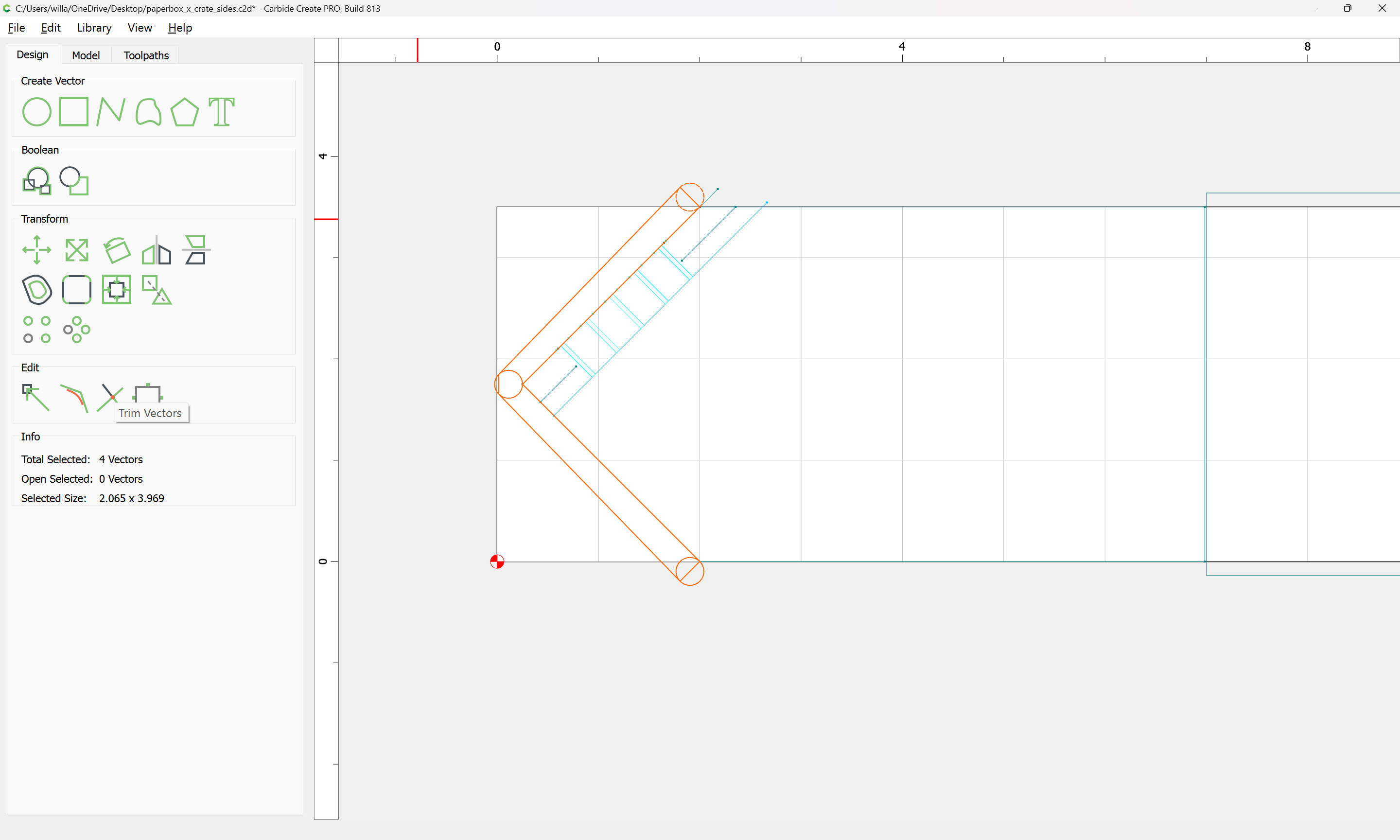
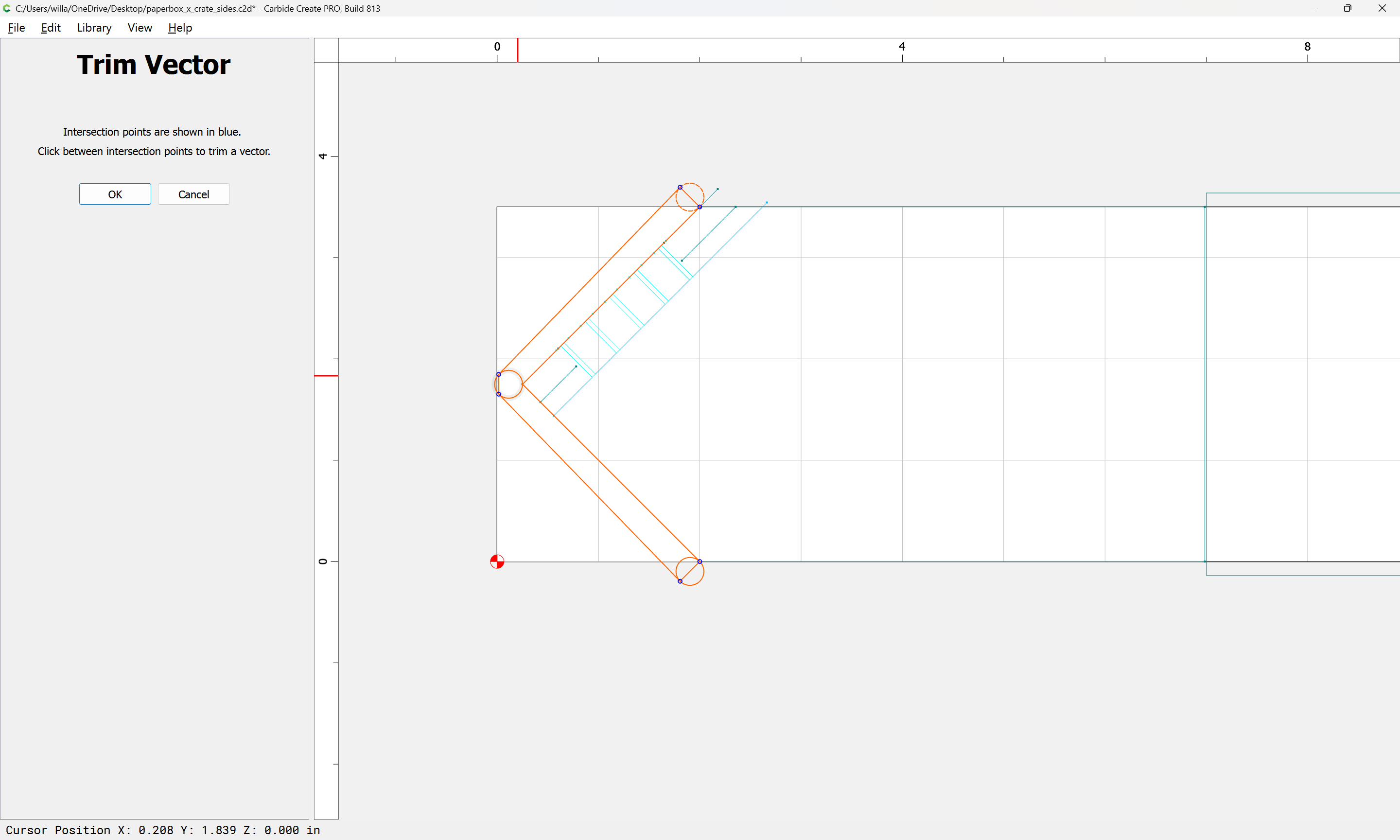
We can then draw in geometry to allow using Trim Vectors to get down to what is wanted (or further Boolean operations could be used)
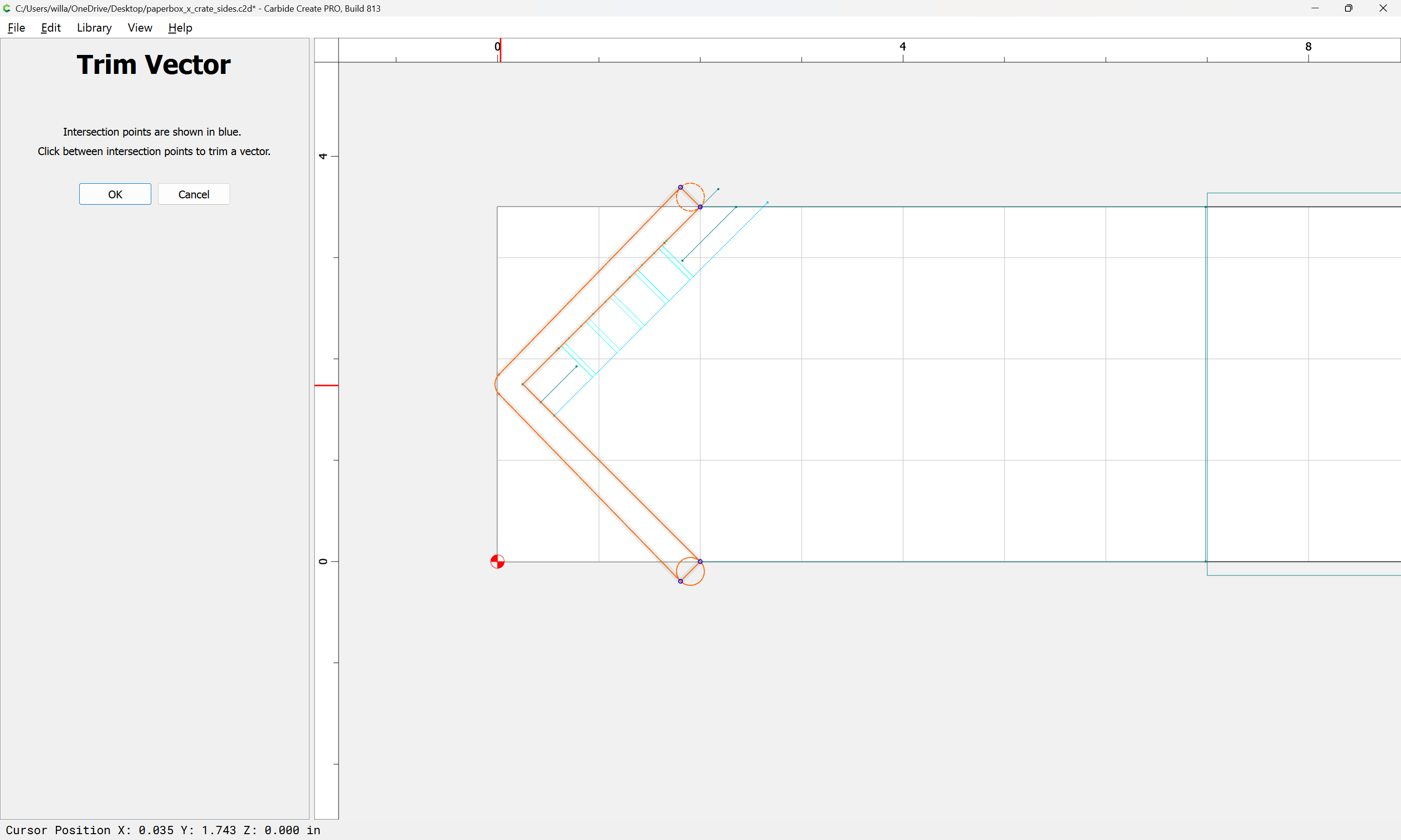
Click to remove what is not wanted:
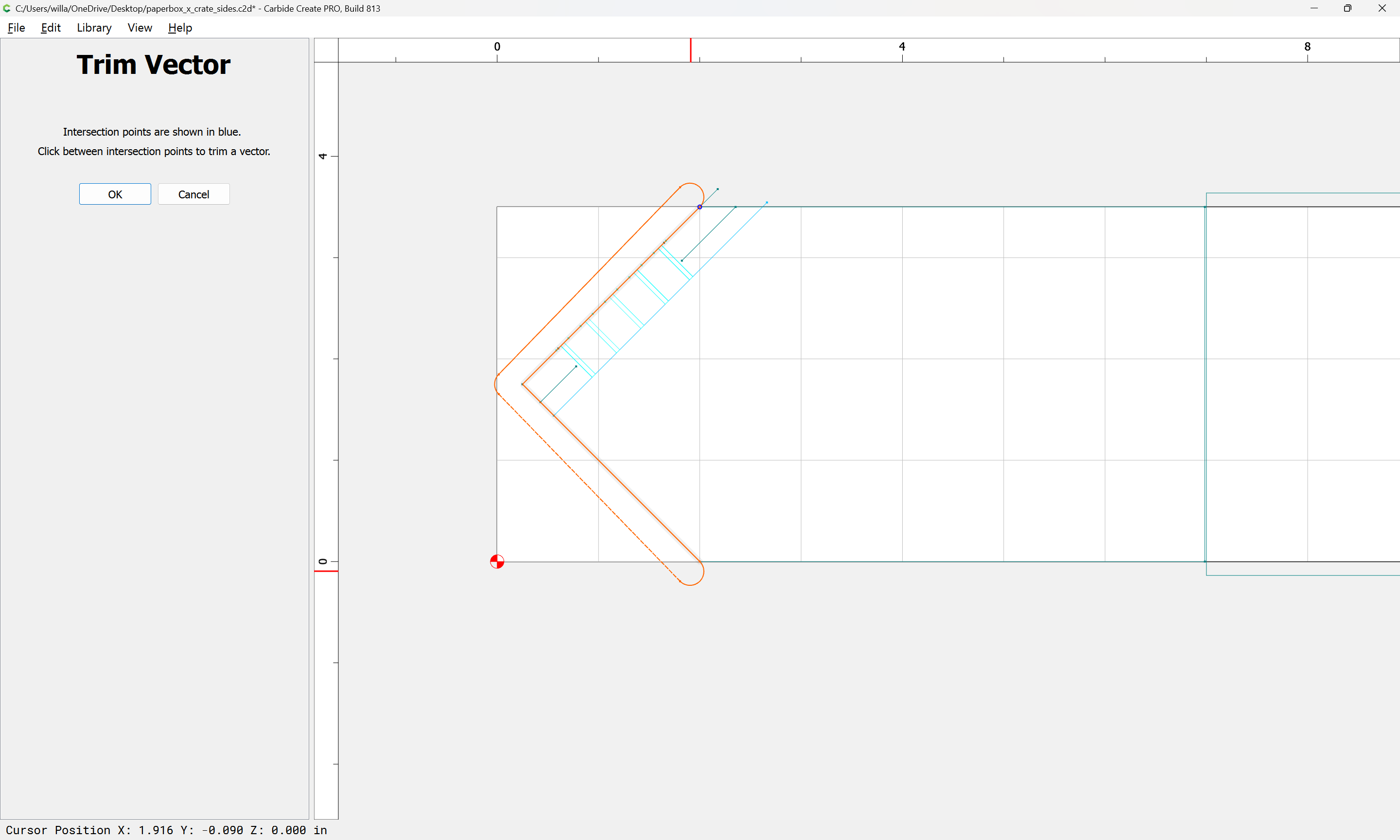
eventually arriving at:
OK
OK
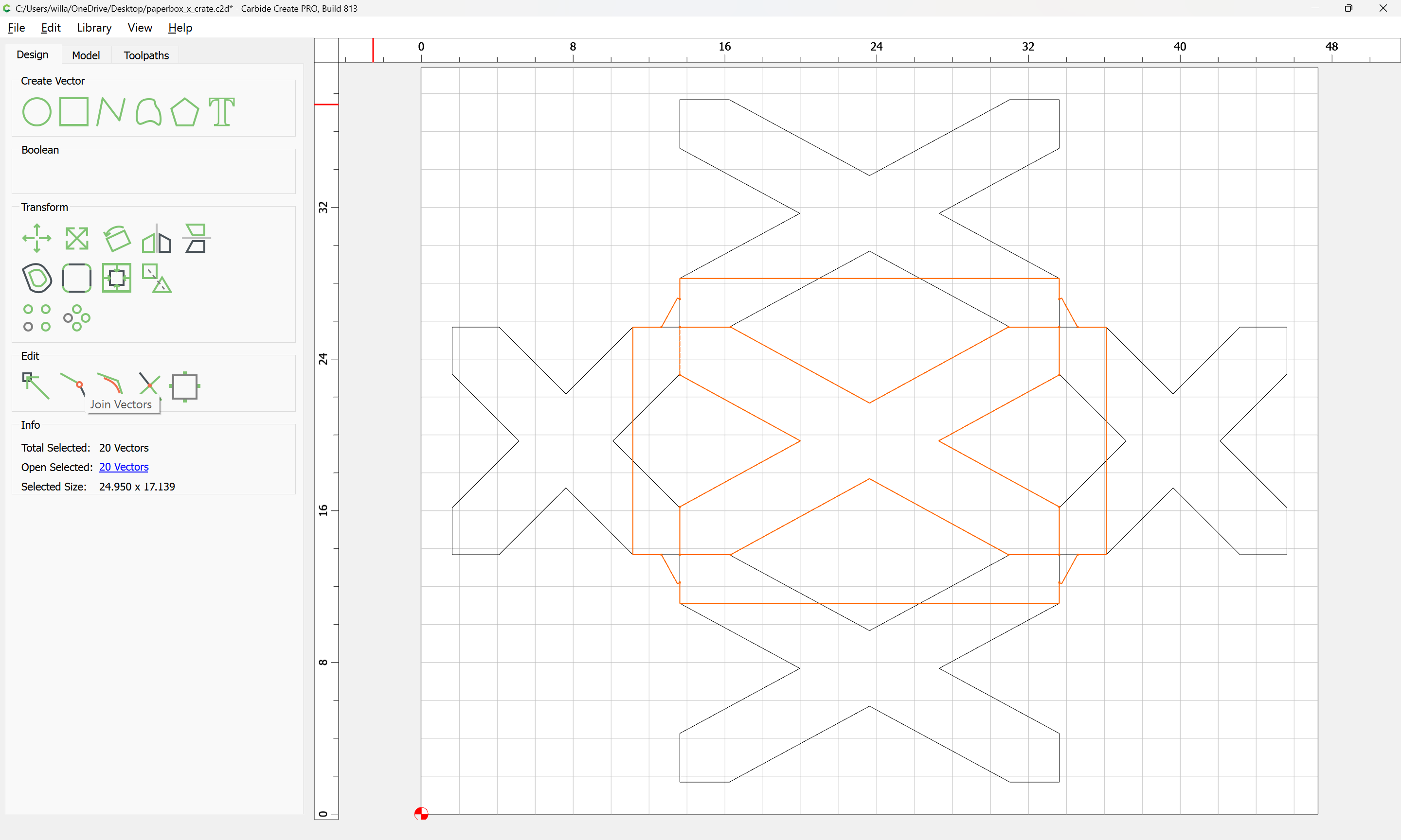
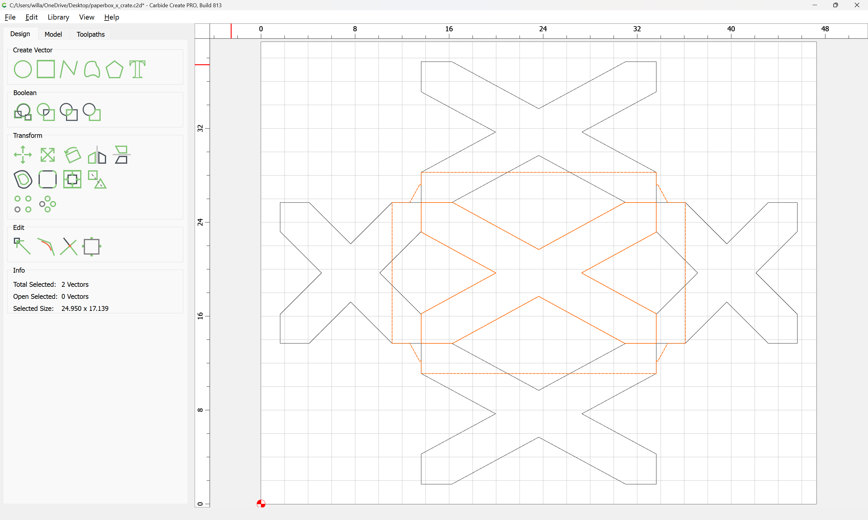
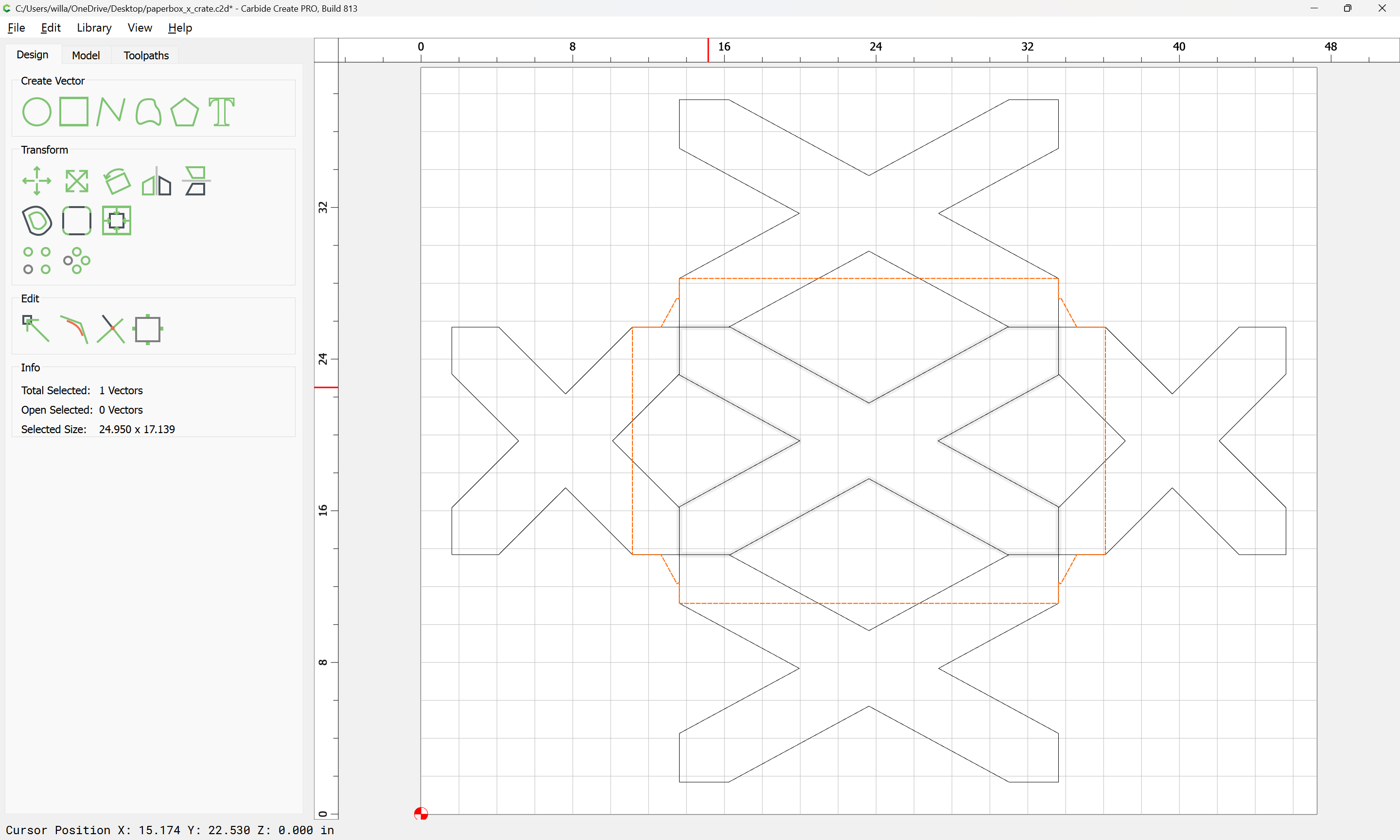
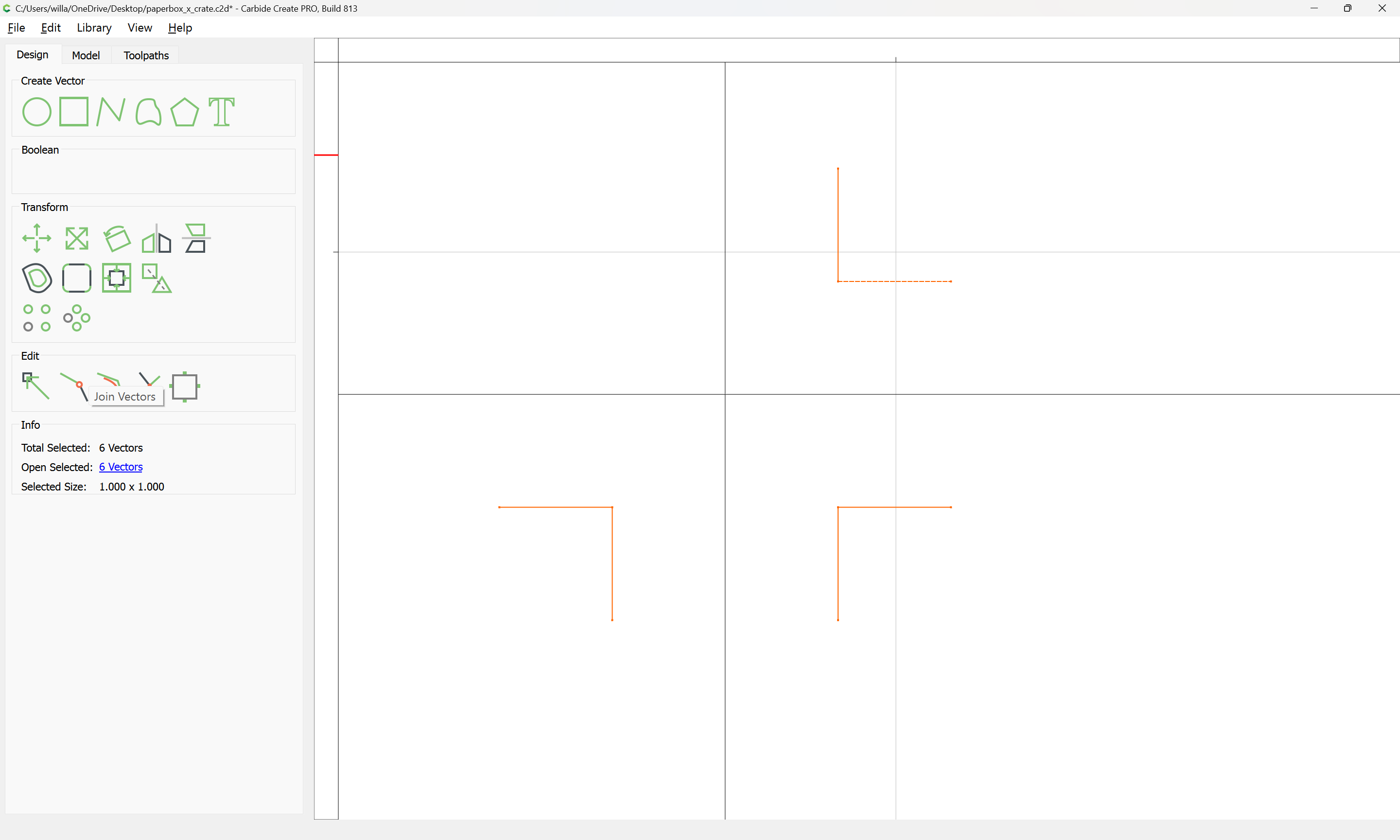
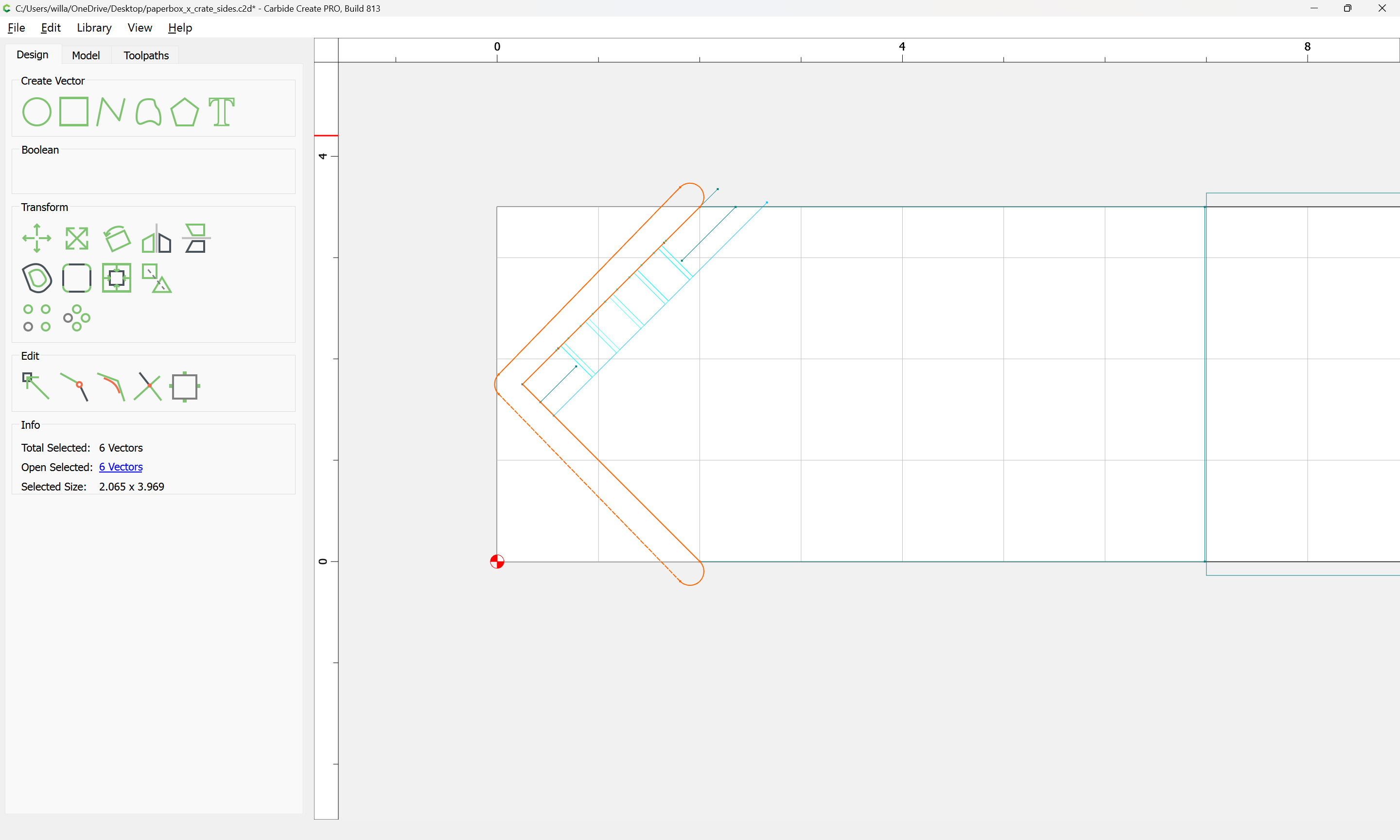
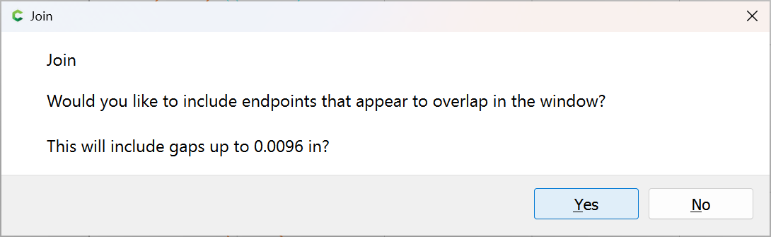
Use Join Vectors to close things up:
shift-click to deselect what is wanted:
then delete:
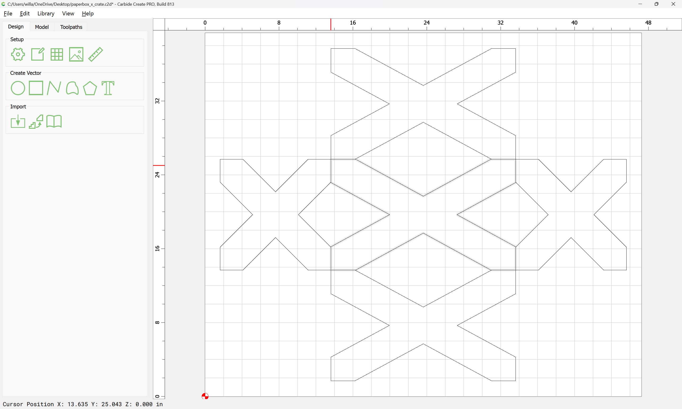
Remove the top/bottom:
and replace them with the fixed version:
1 Like
WillAdams
February 2, 2025, 2:00am
3
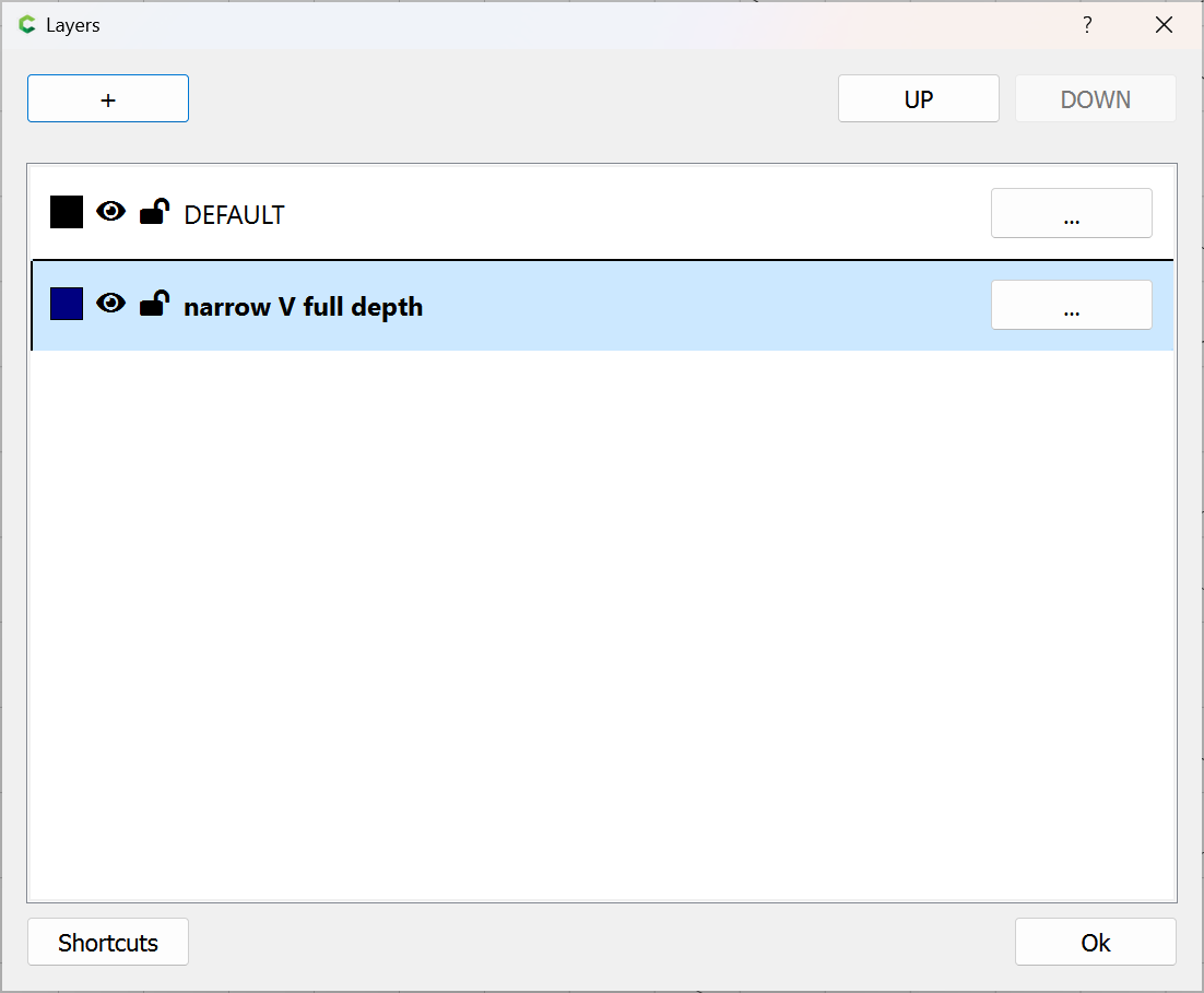
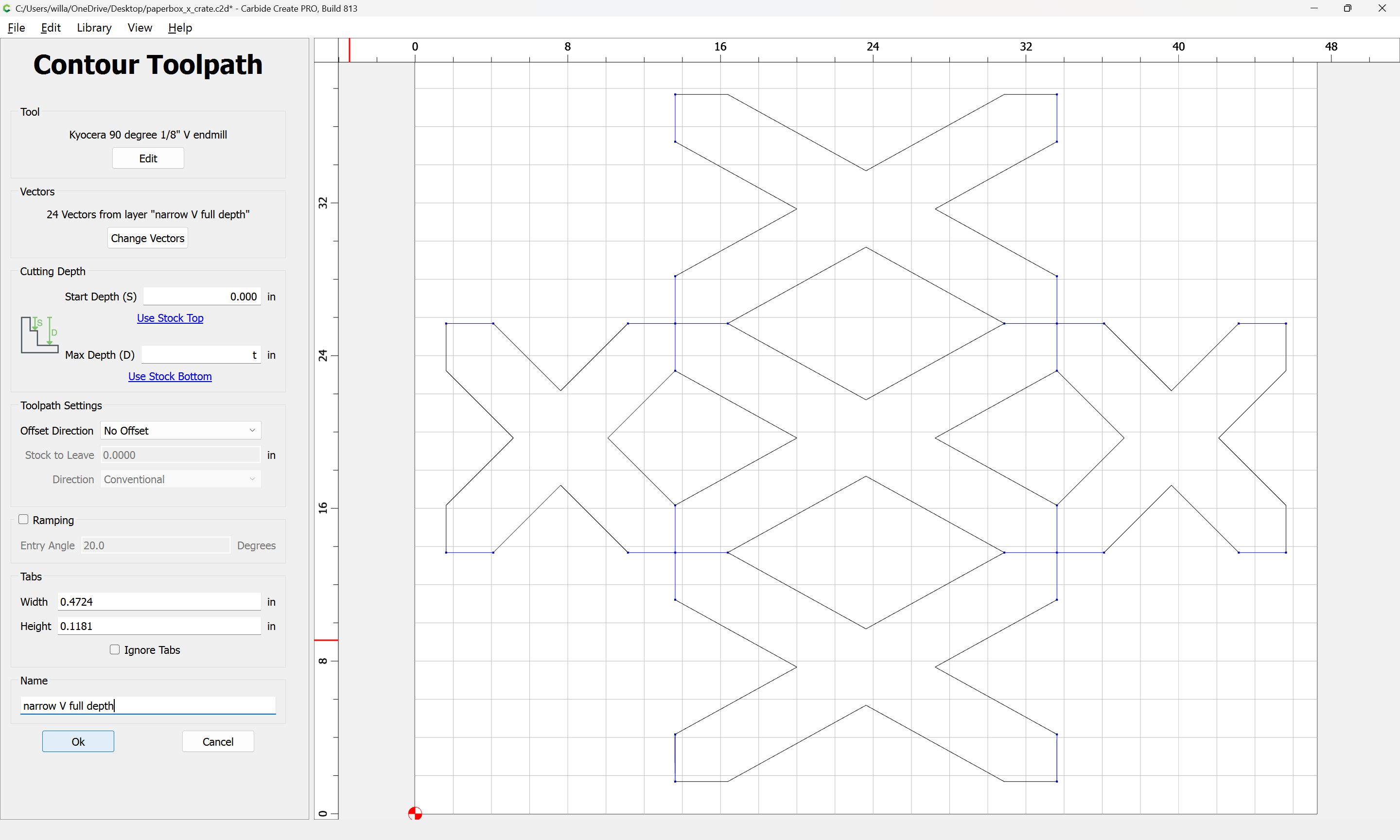
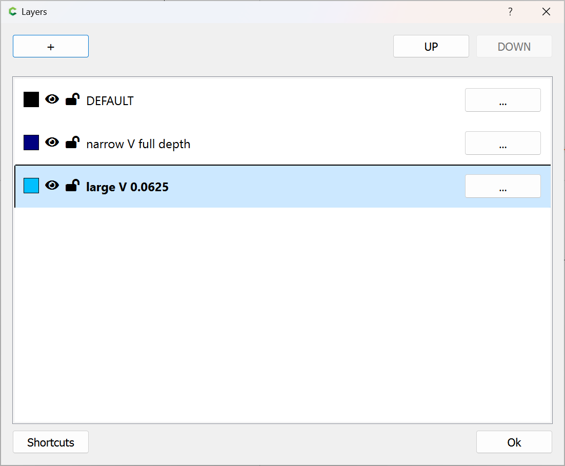
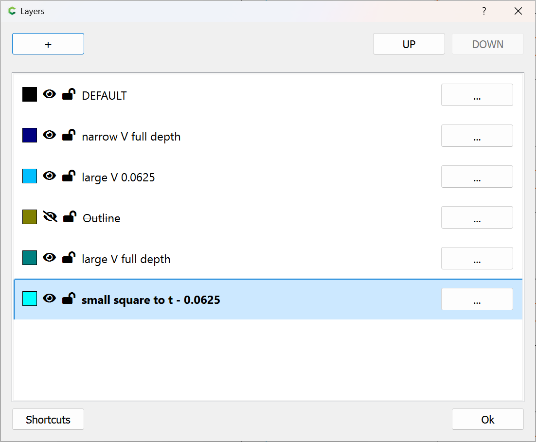
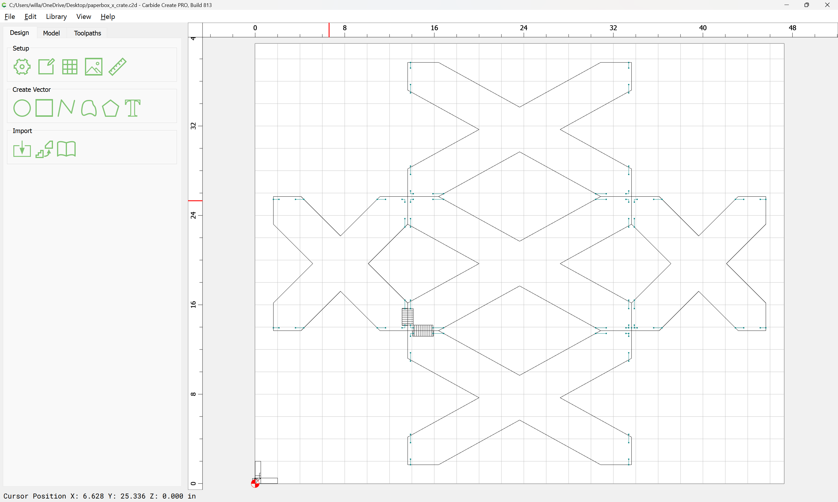
There are several different toolpaths needed — the simplest (invariant) is a narrow V tool to cut along the edges of the joinery — since there will be a number of overlapping toolpaths, we create a separate layer for each, starting with this toolpath:
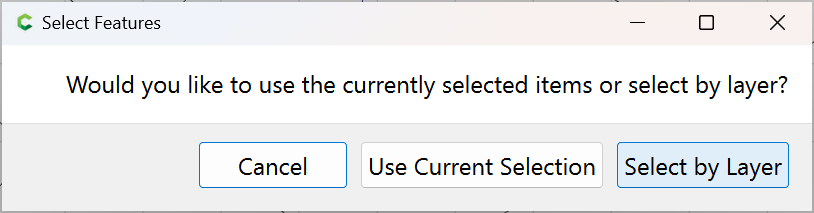
Select by Layer
WillAdams
February 2, 2025, 2:42am
4
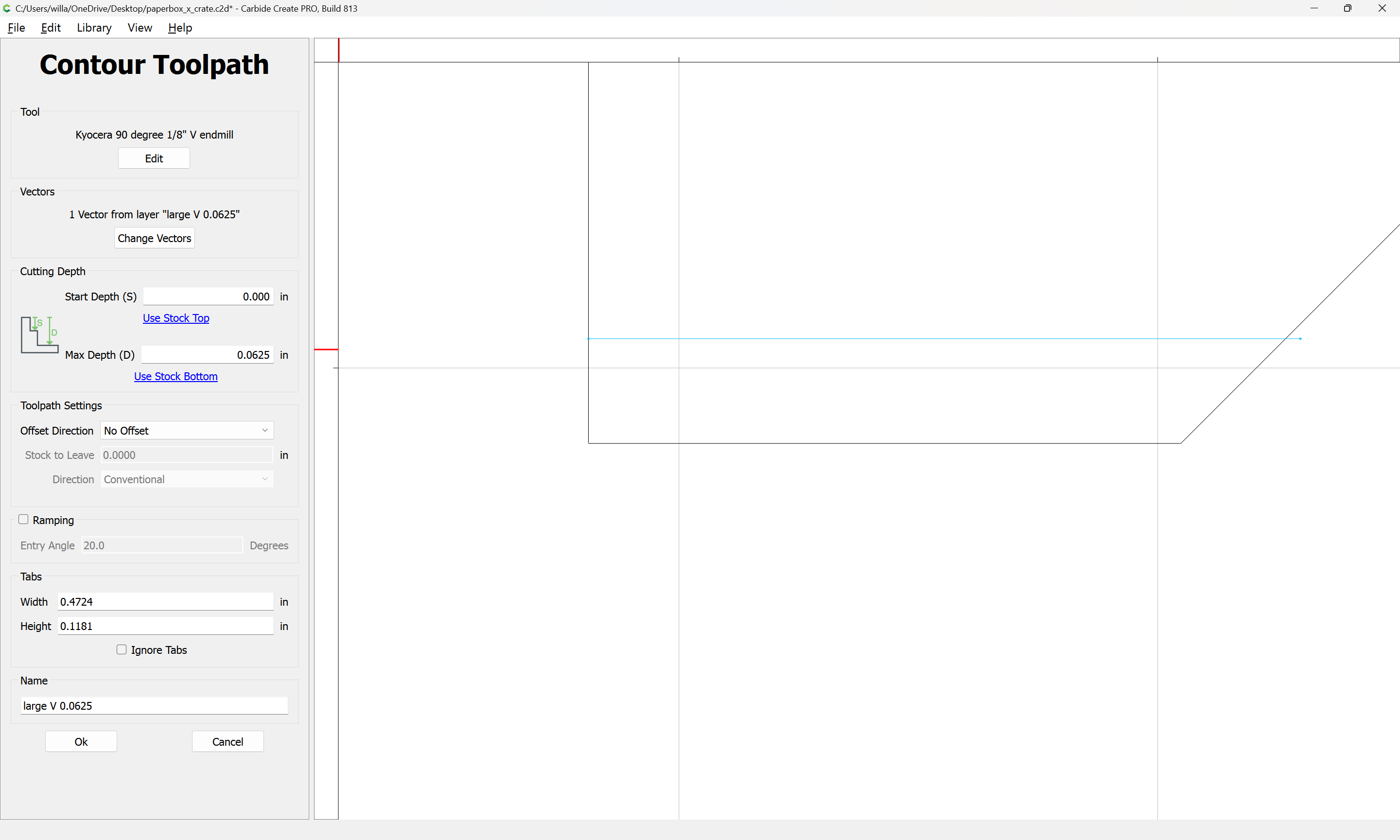
For many complicated projects it is helpful to draw up the tools/cut in profile:
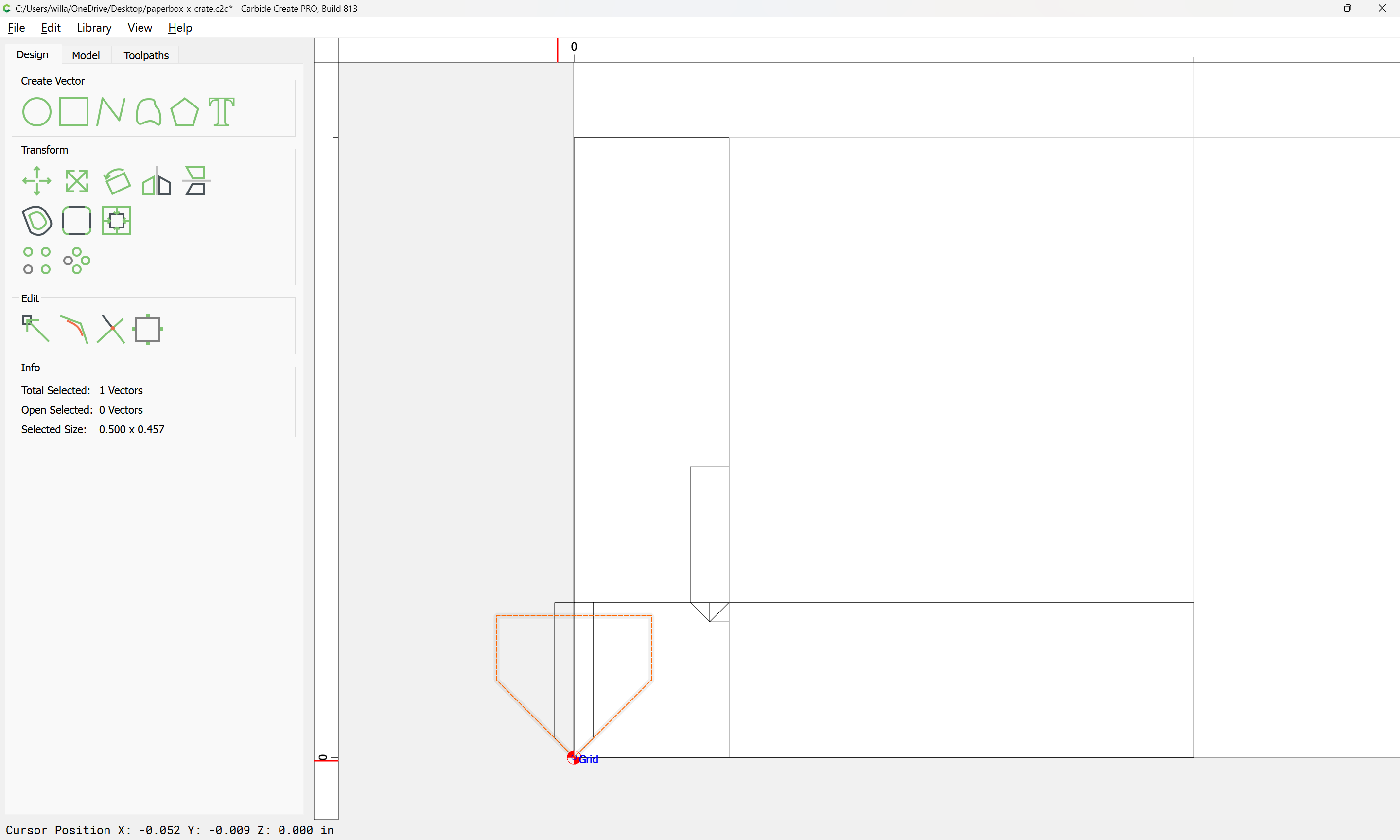
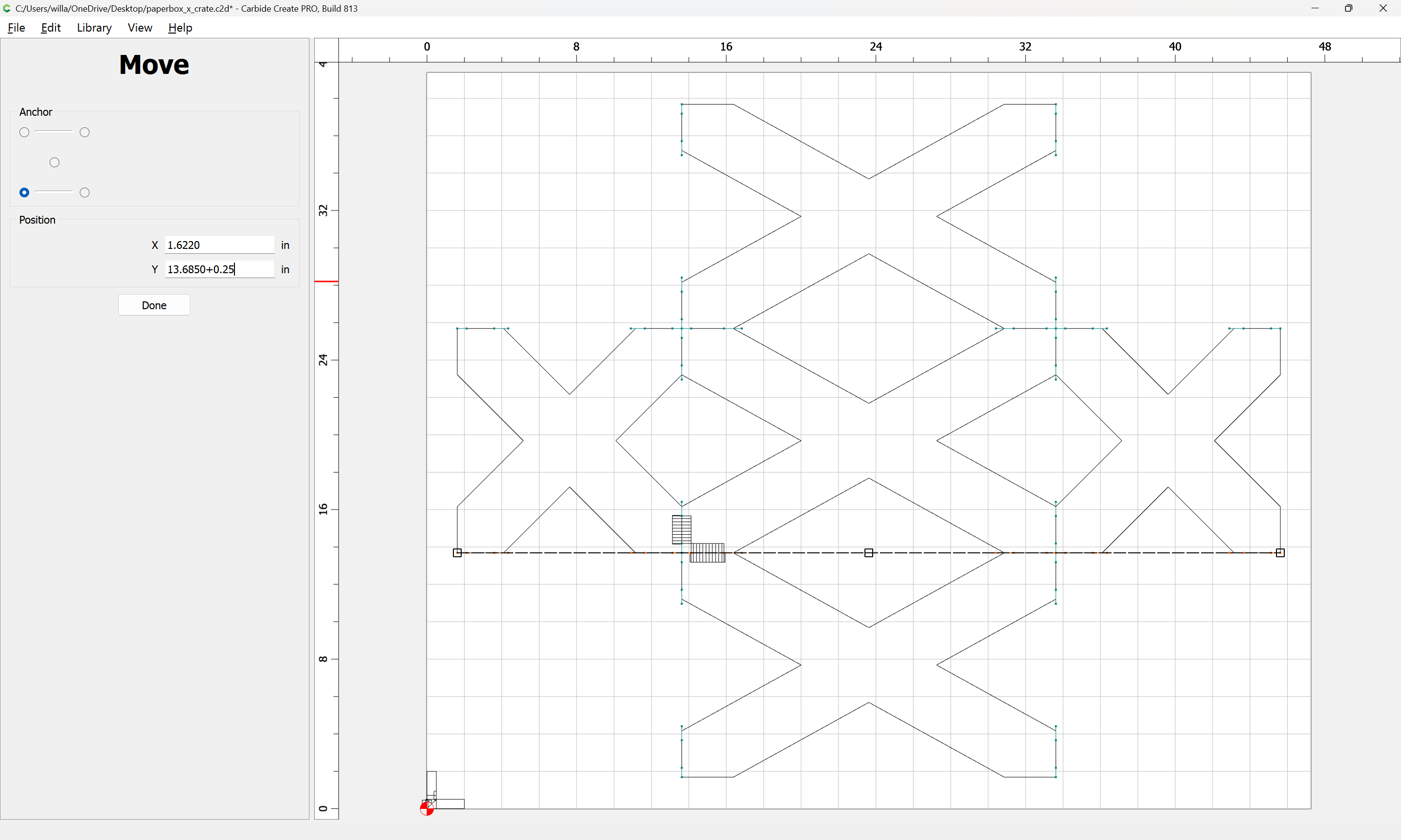
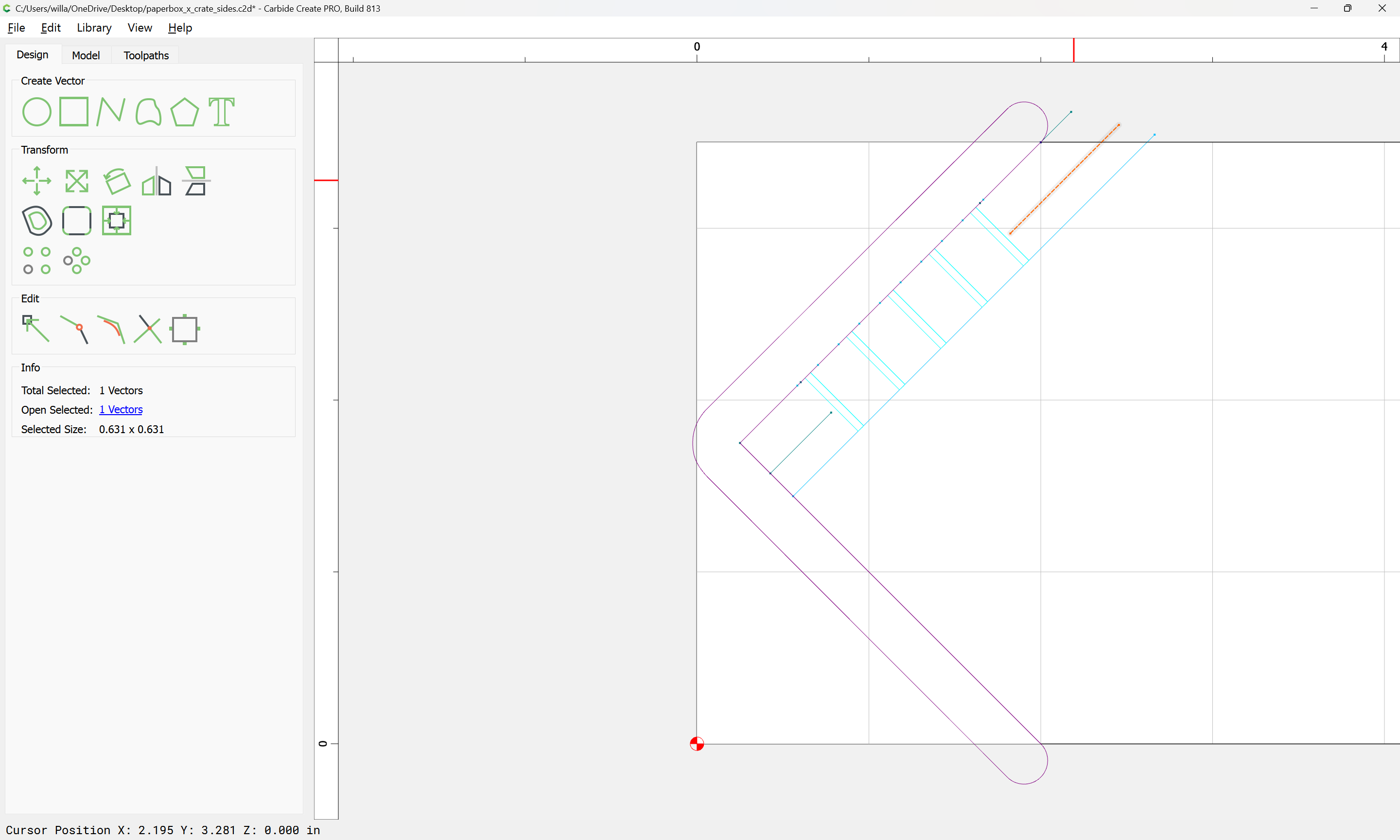
The next easiest cut to draw in is the cut along the top edge, also with a V endmill — note that while this is best done with a large 90 degree V endmill, it is helpful to position it as if cutting with the small tool:
This is inset 0.0625" from the top edge:
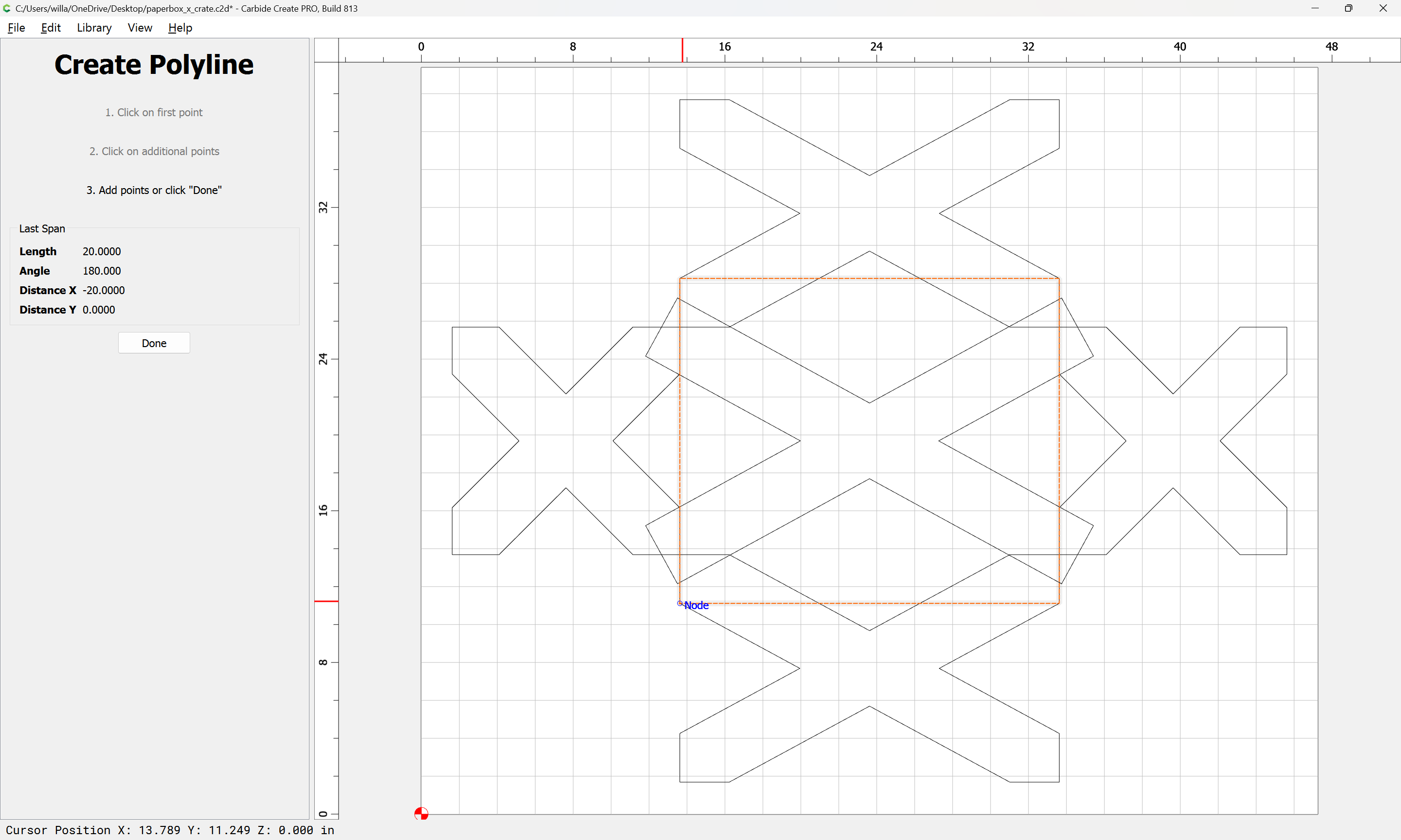
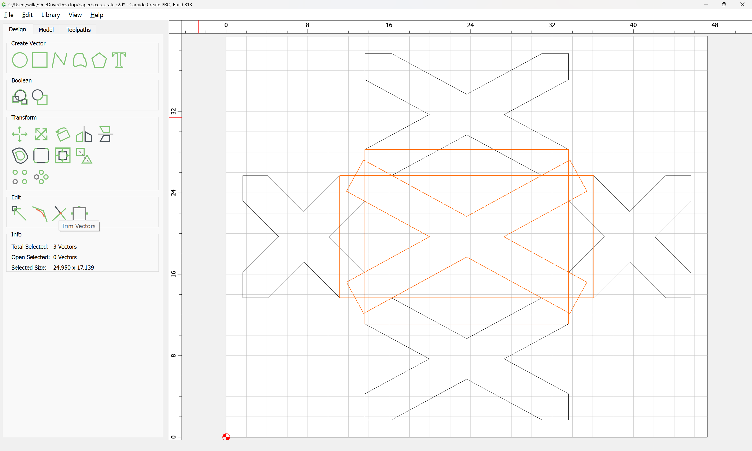
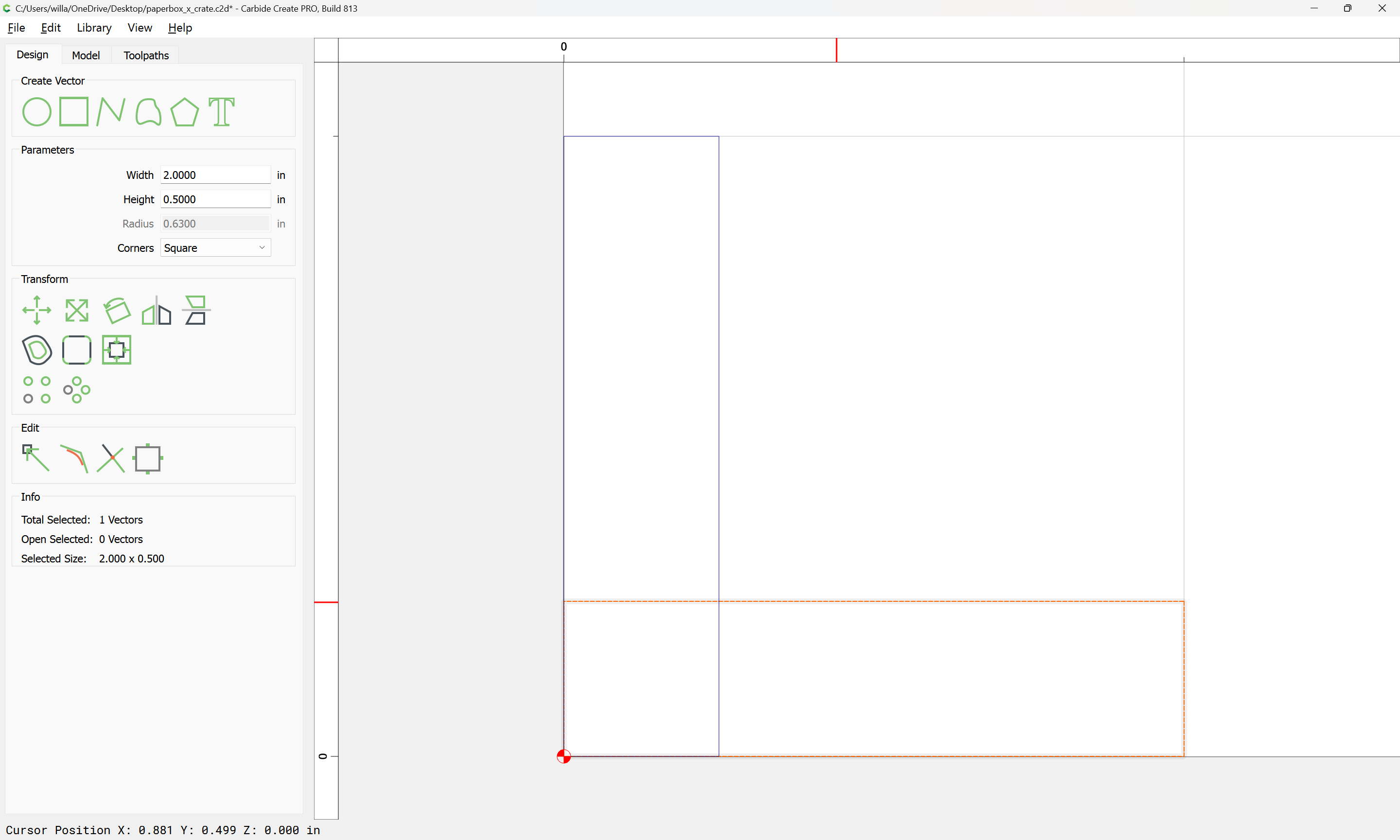
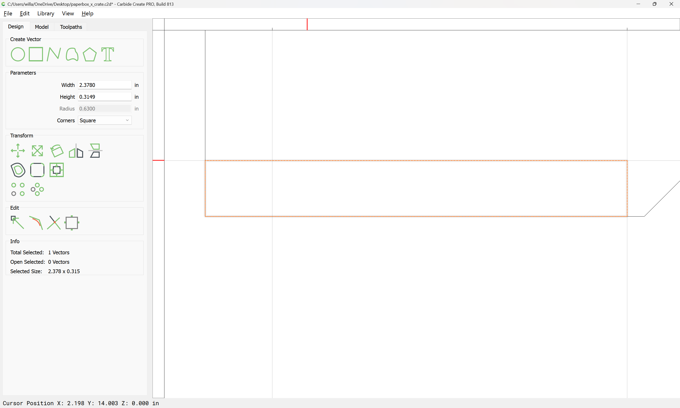
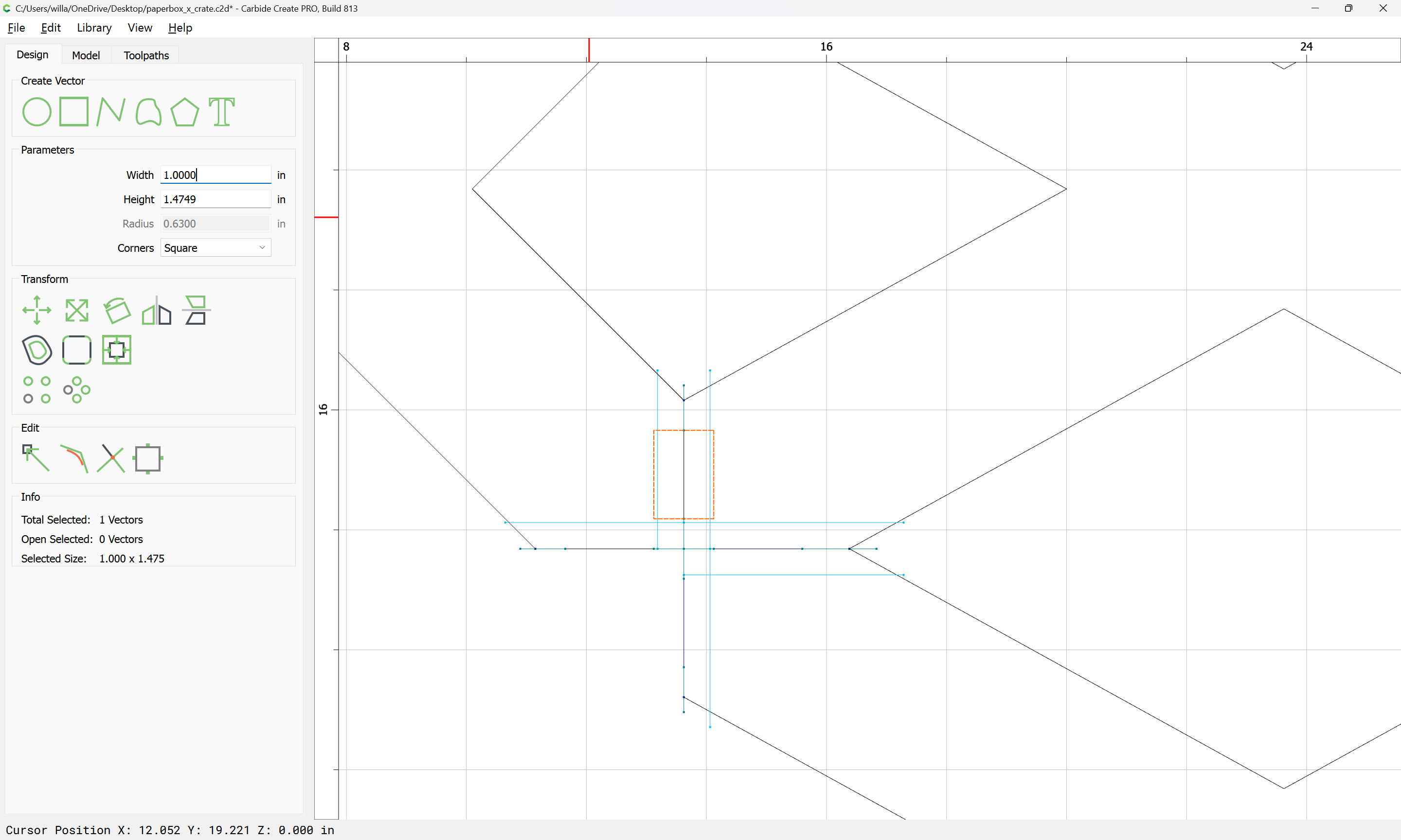
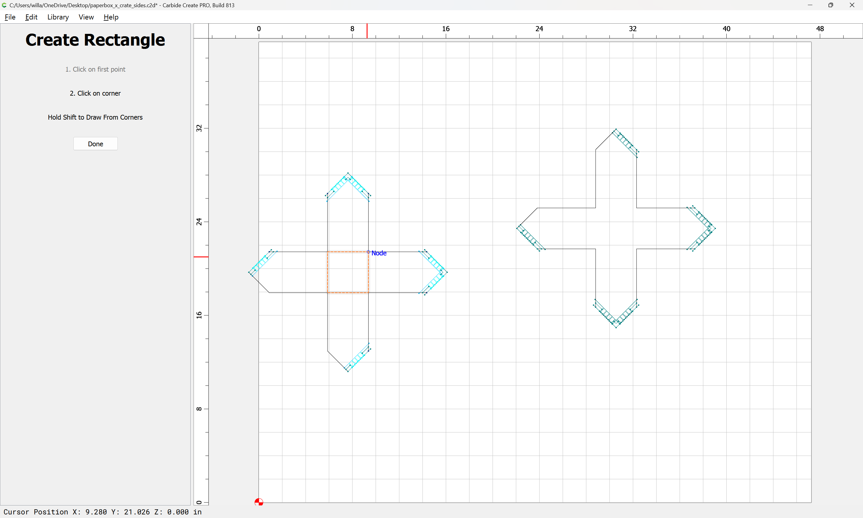
One way to draw this is to first draw a rectangle:
Then assign it a height of
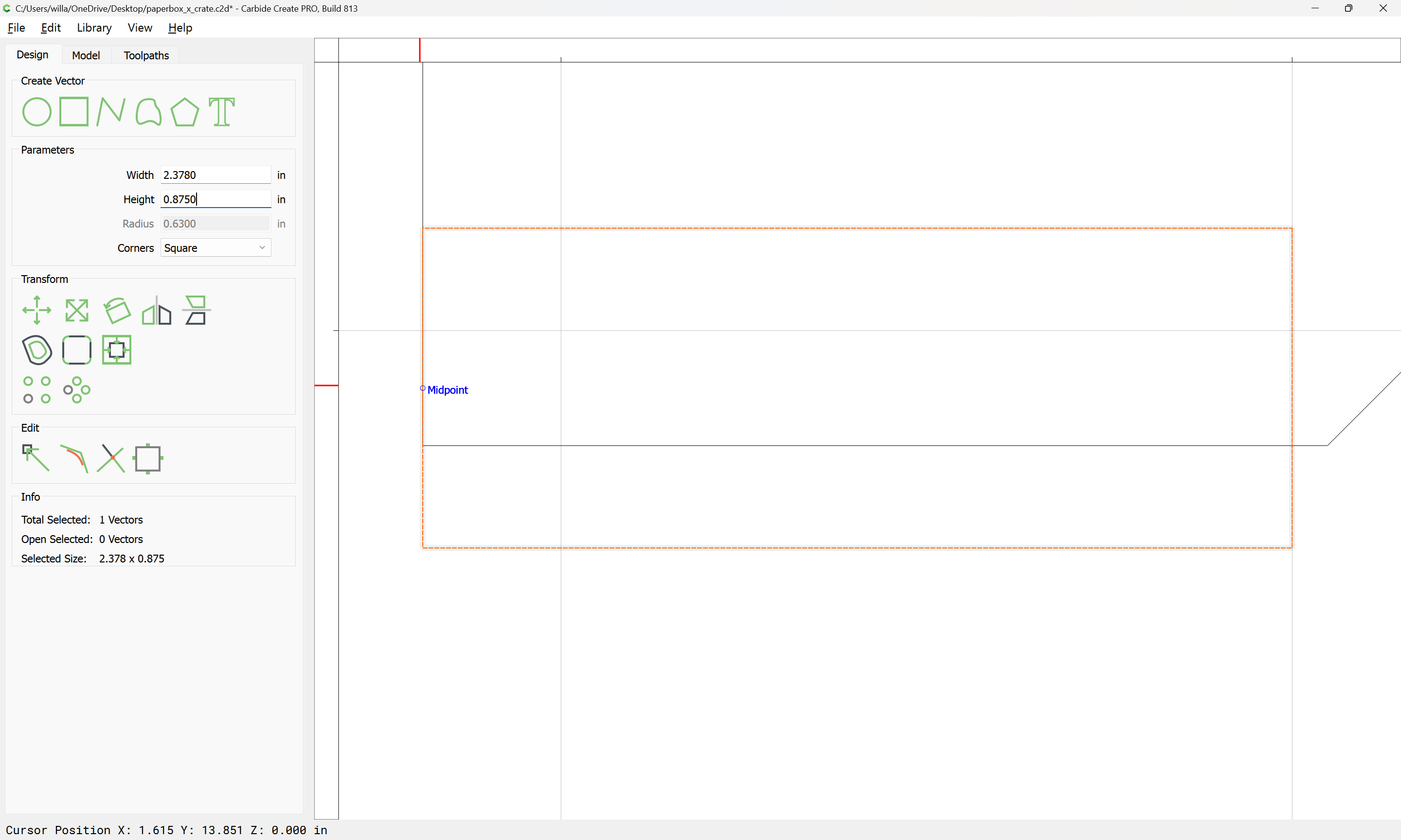
(0.5 * 2) - (0.0625 * 2) == 0.875"
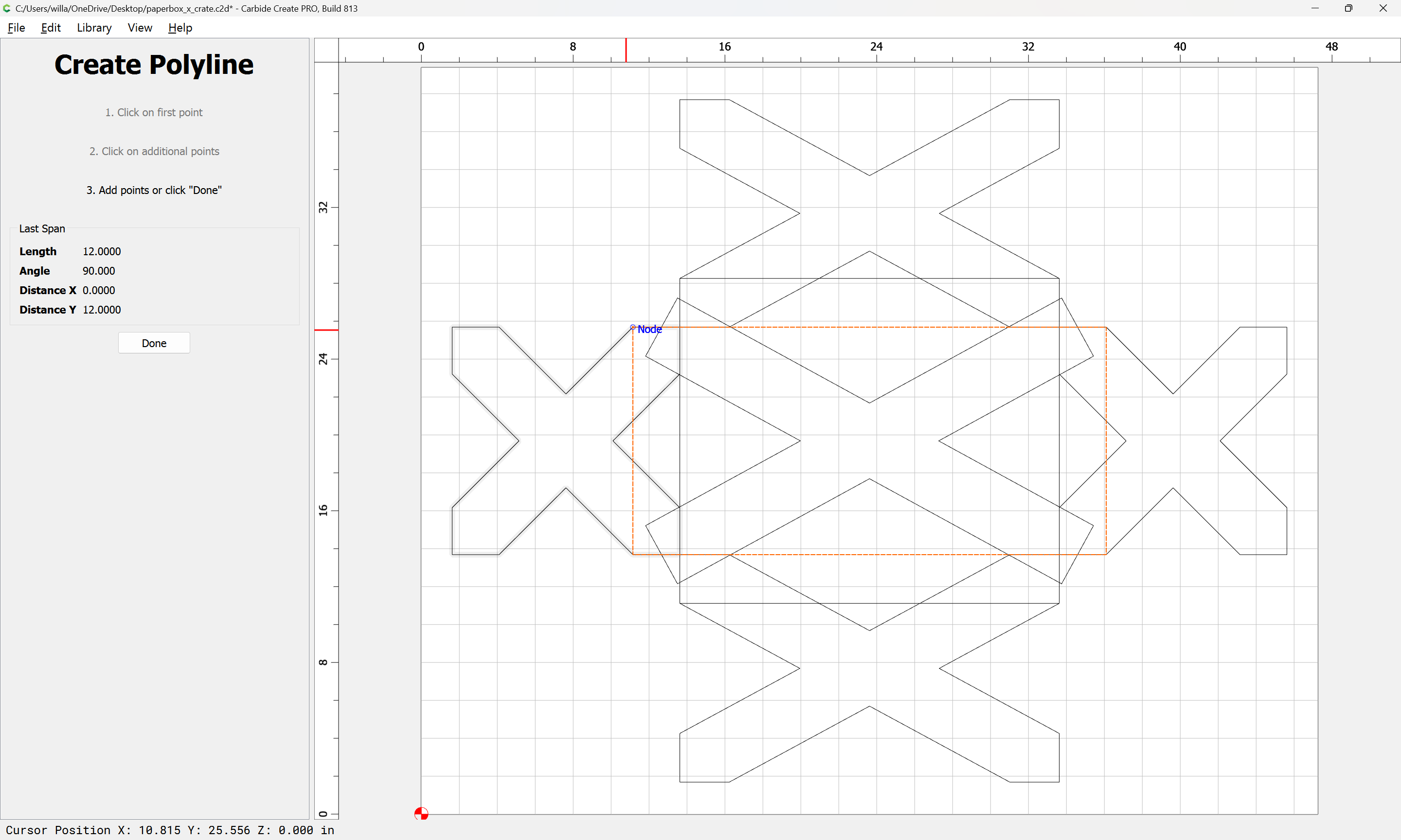
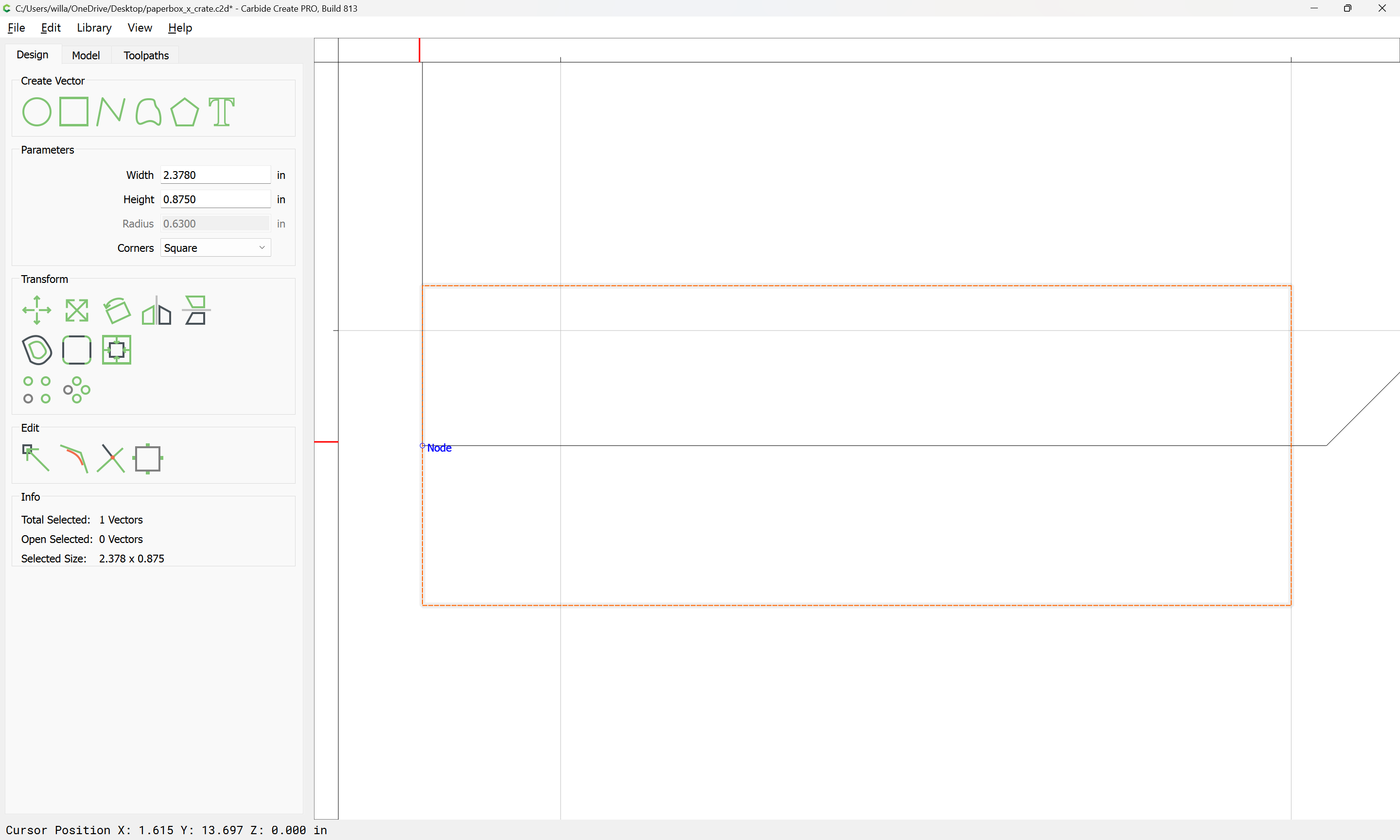
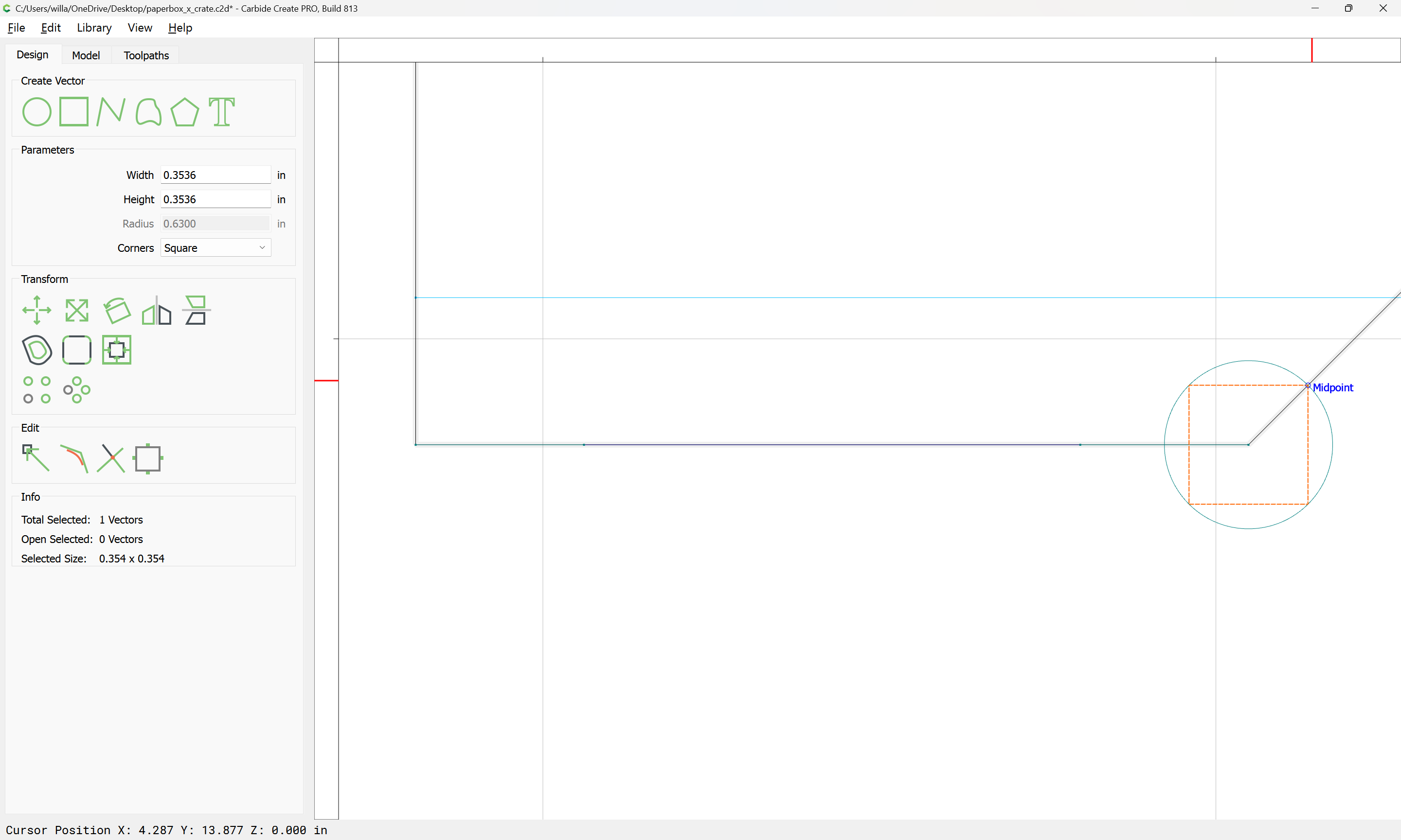
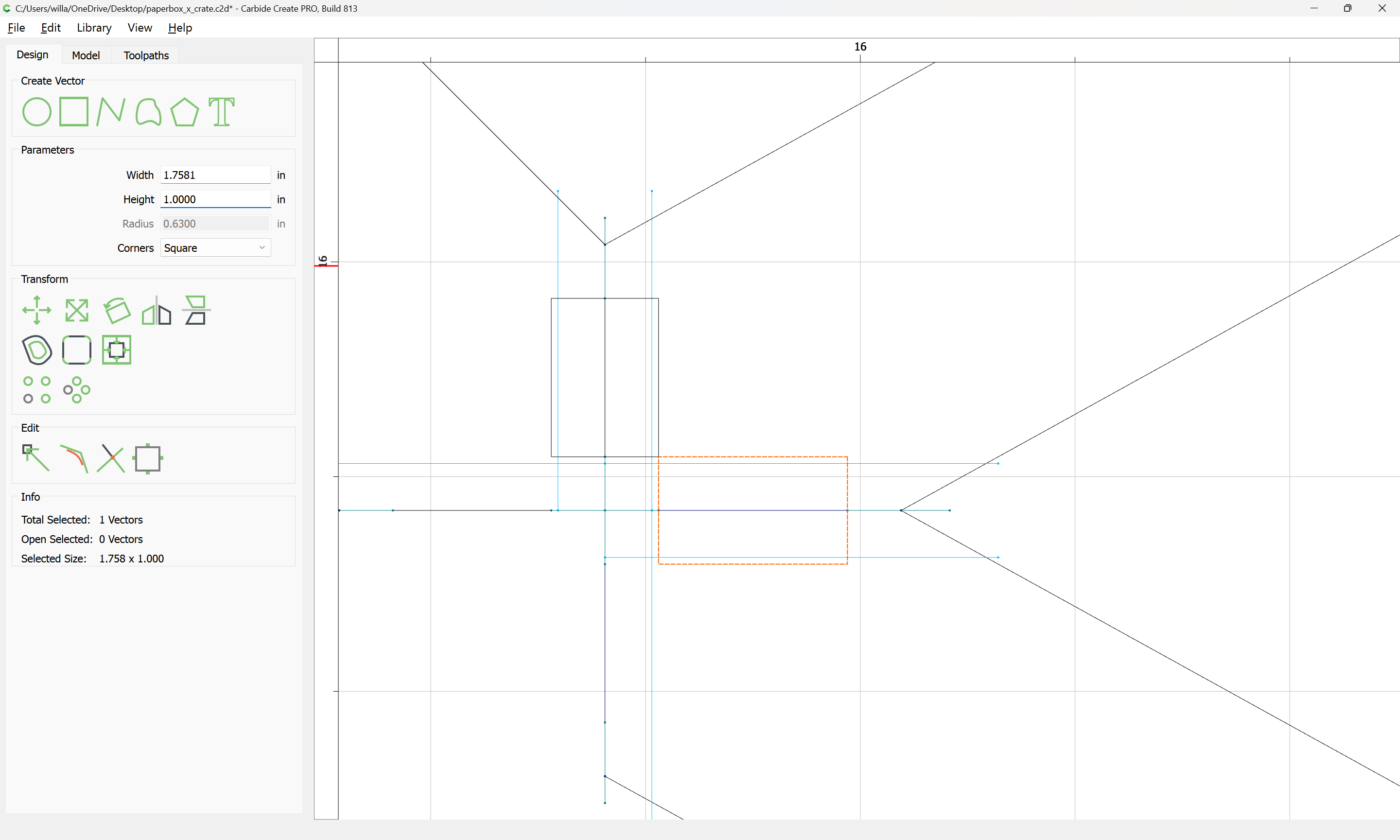
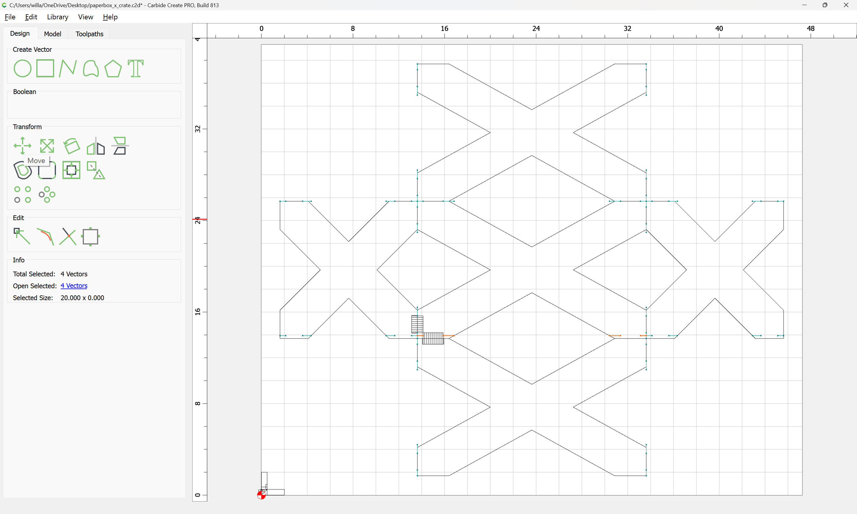
Then use the midpoint to position it:
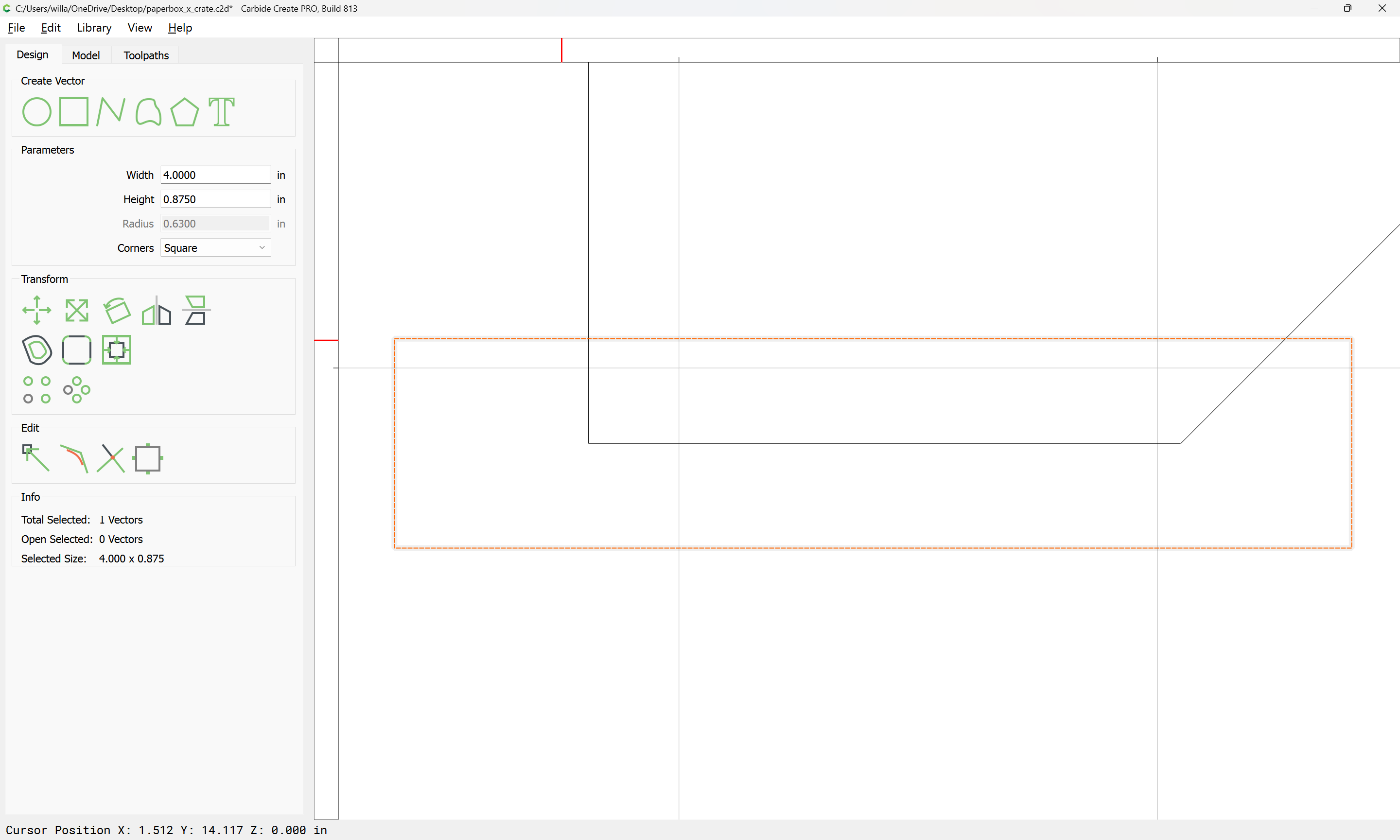
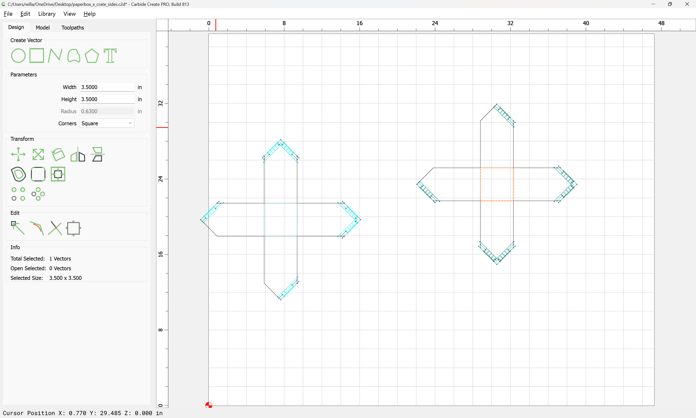
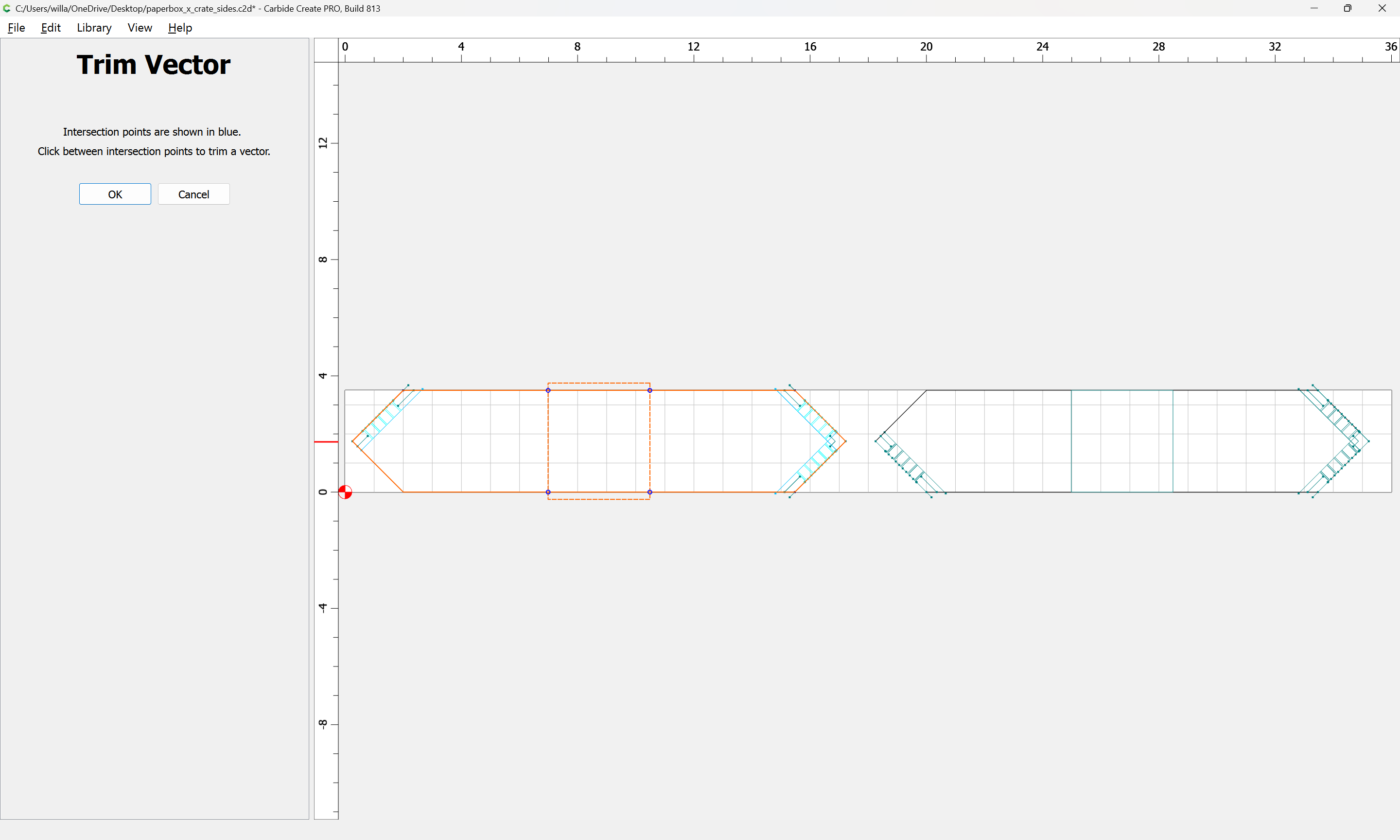
and increase the width until it is wider than the intersecting geometry:
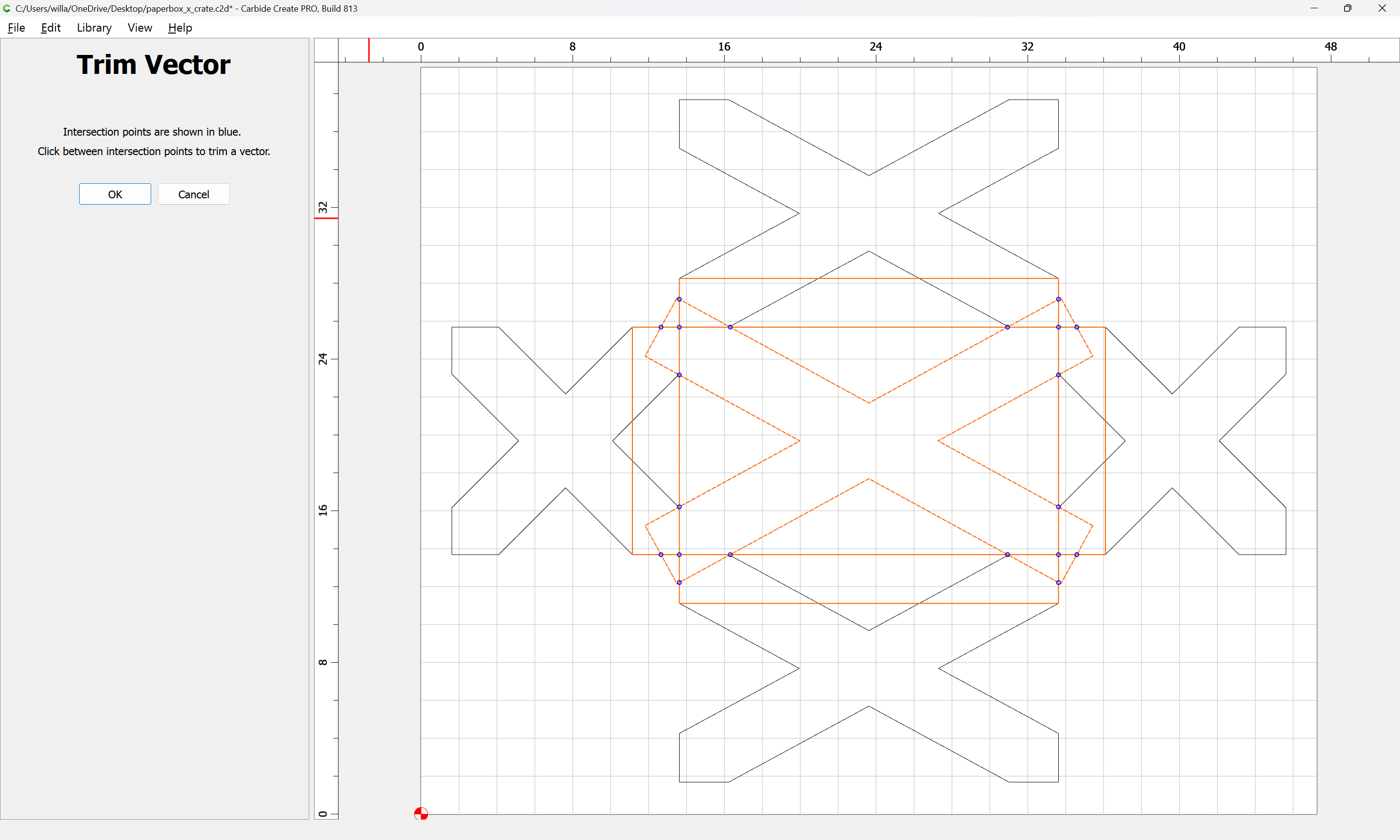
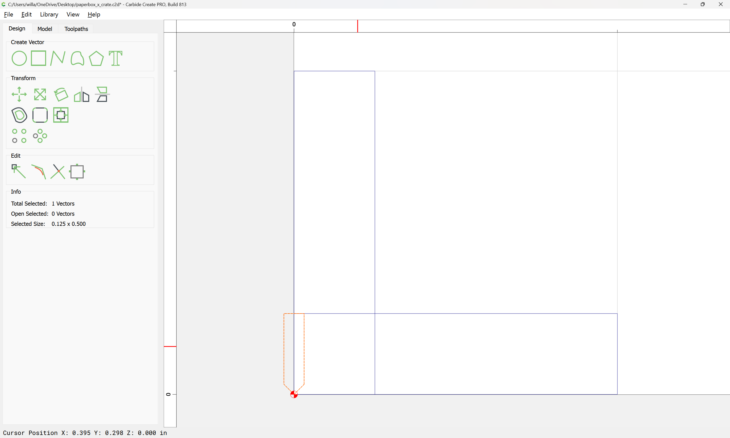
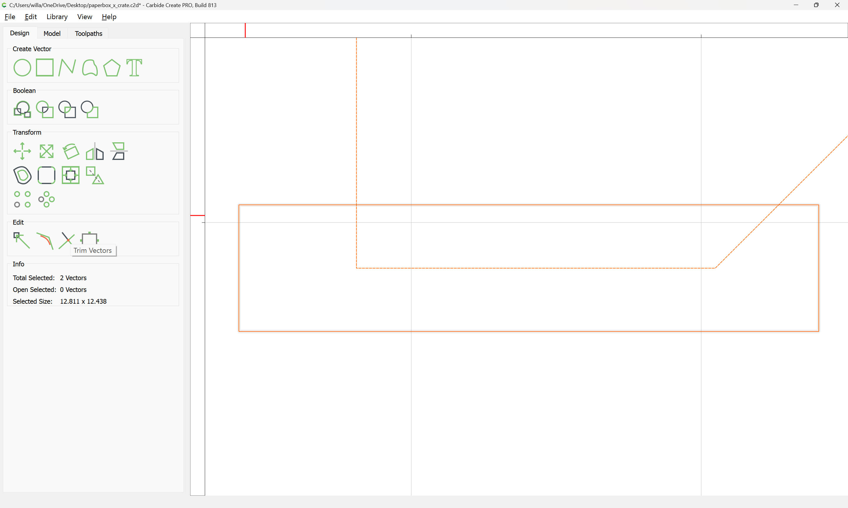
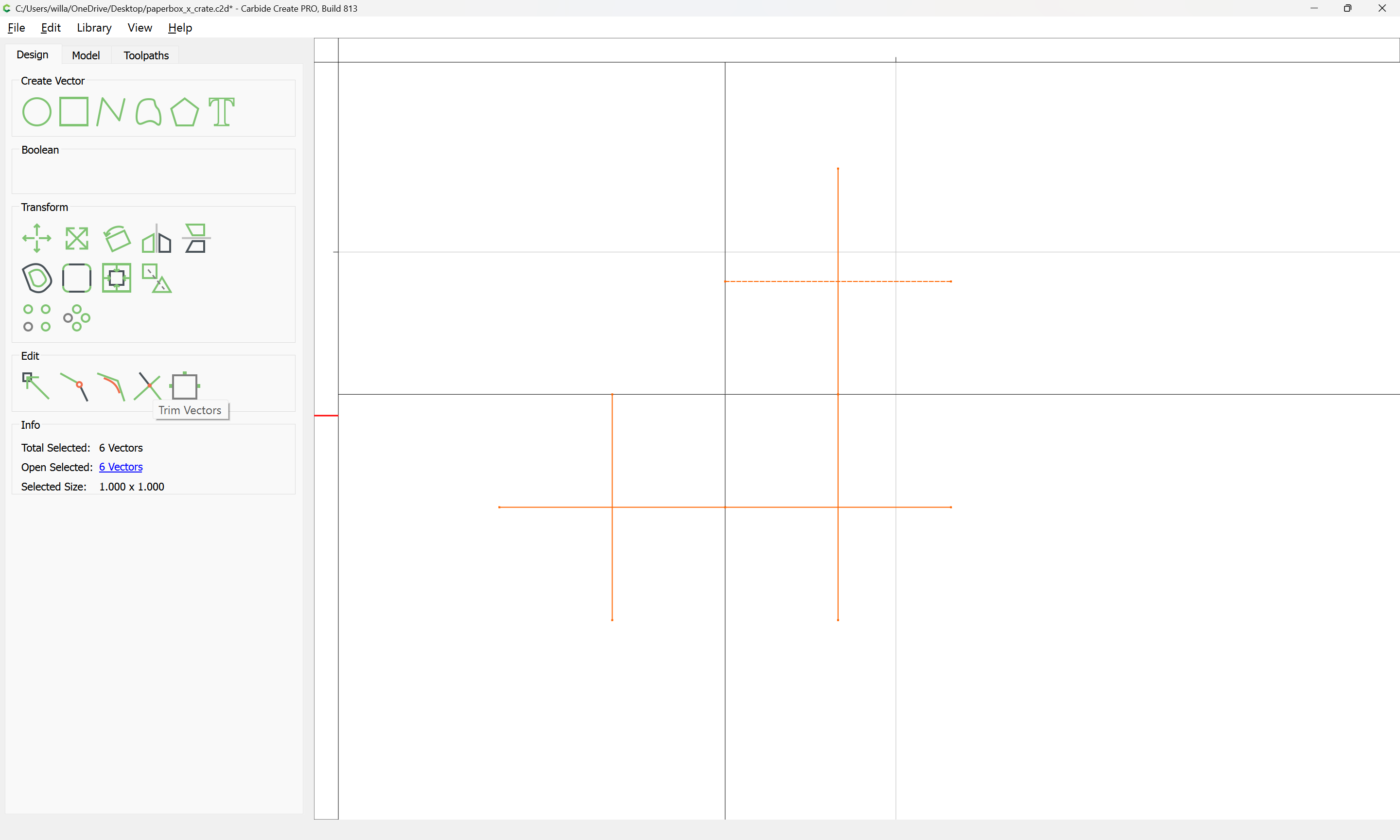
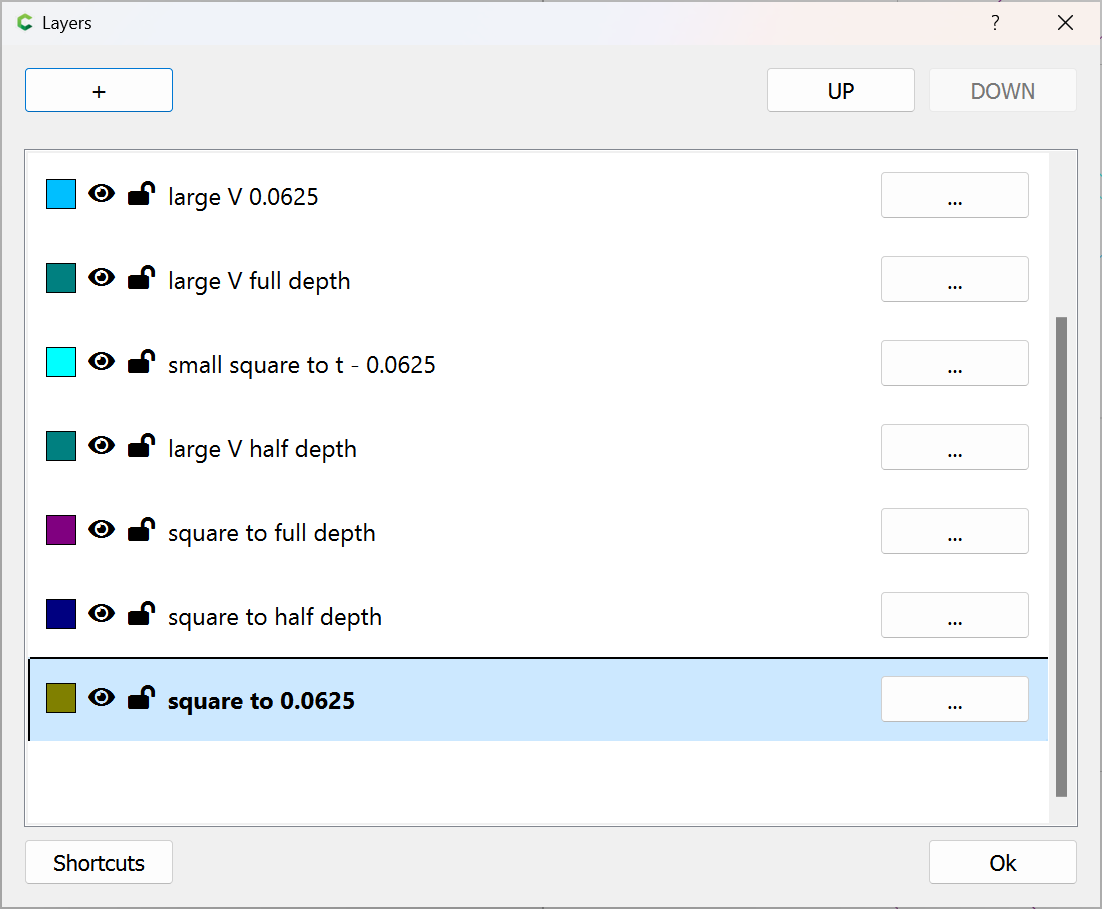
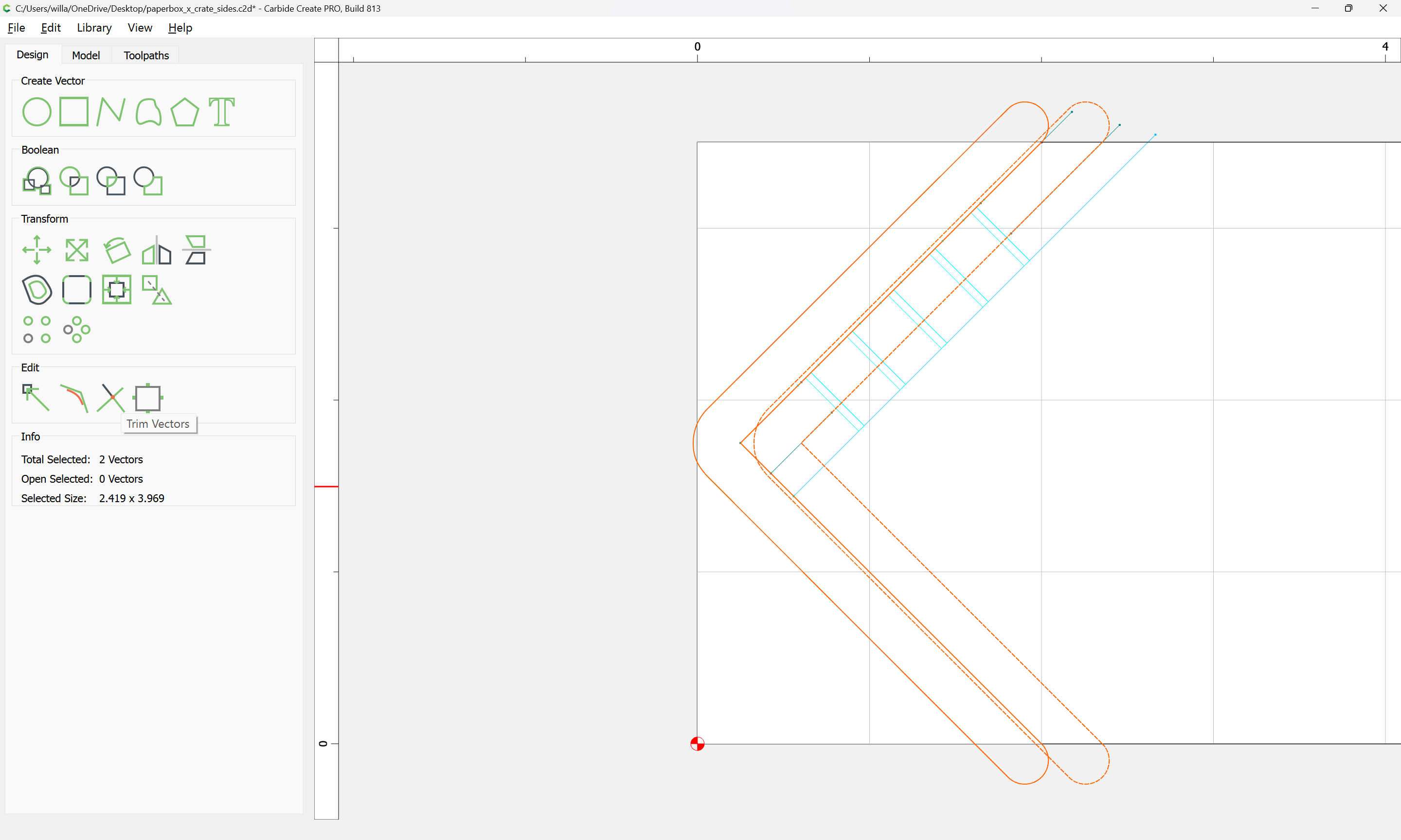
Then select both:
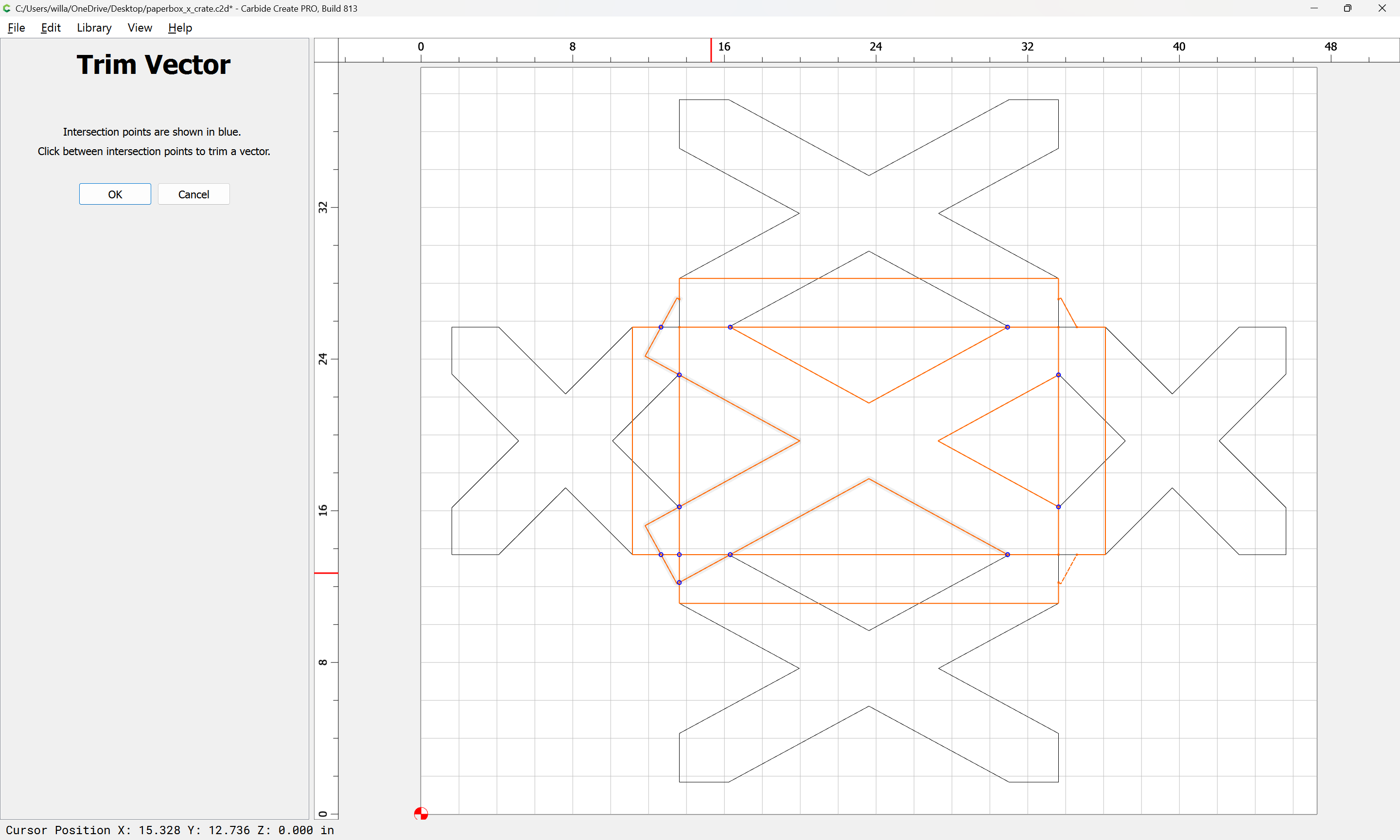
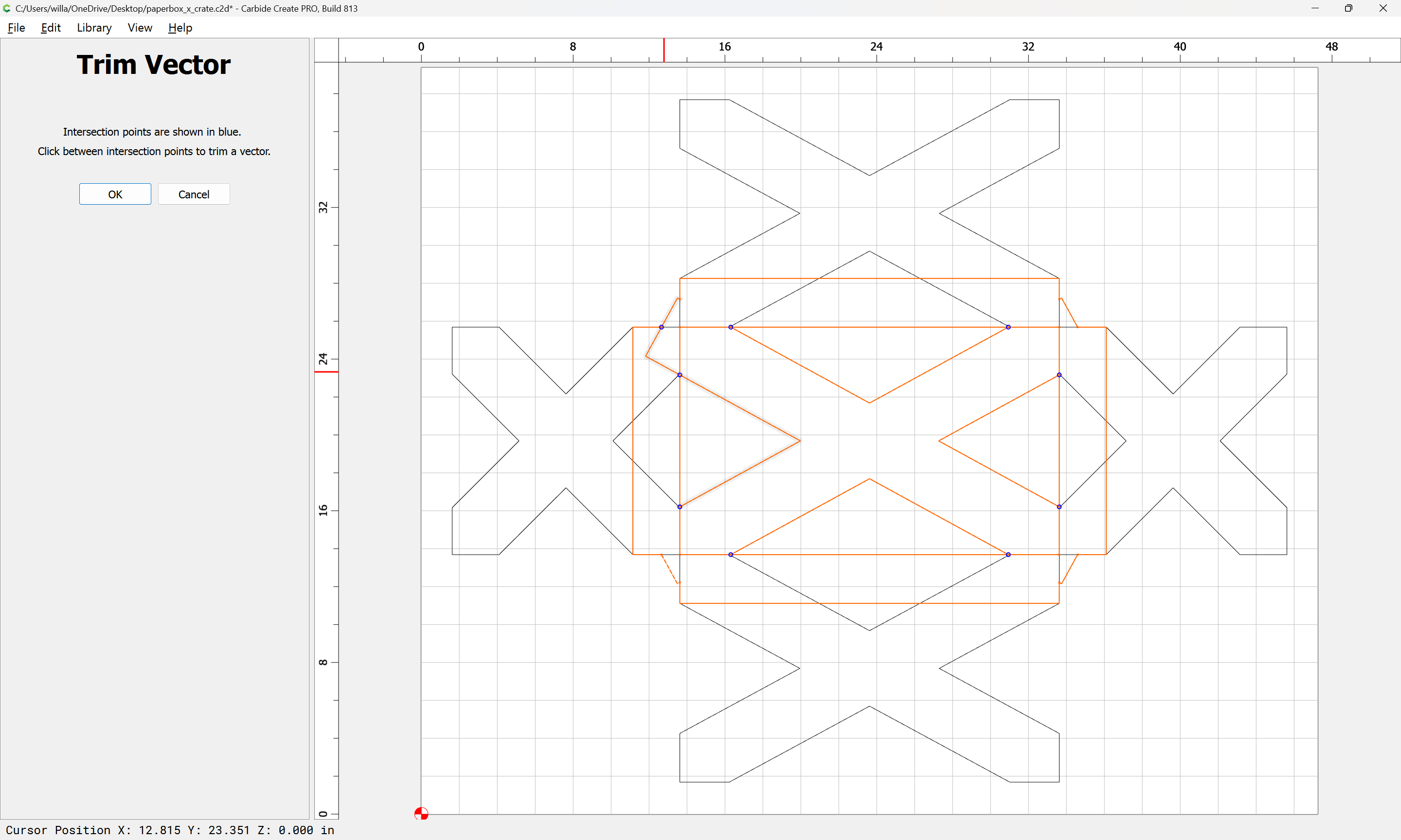
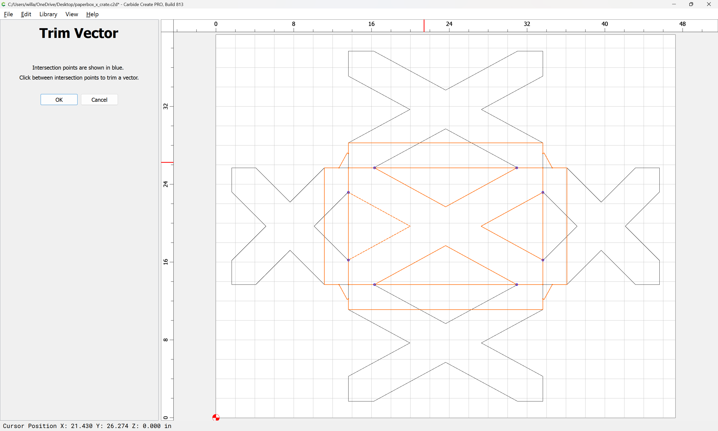
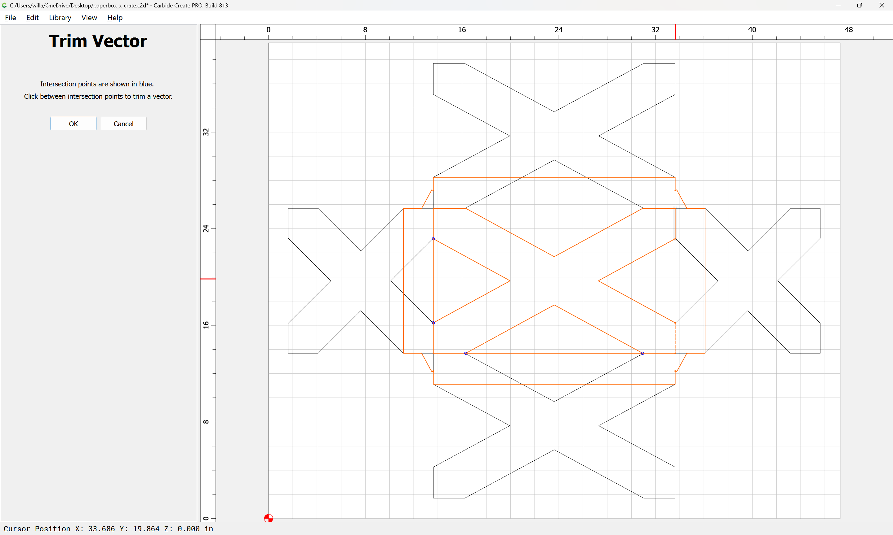
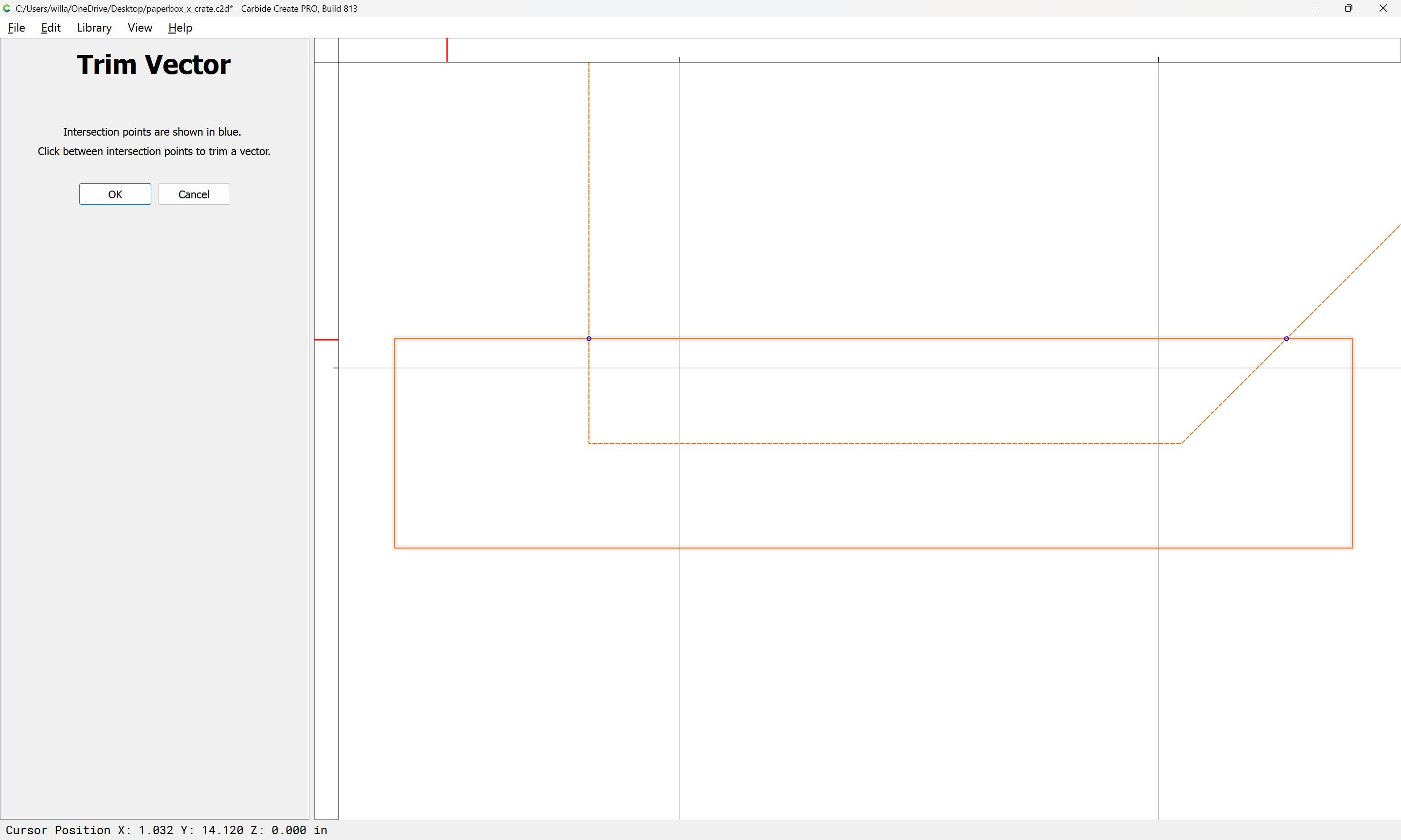
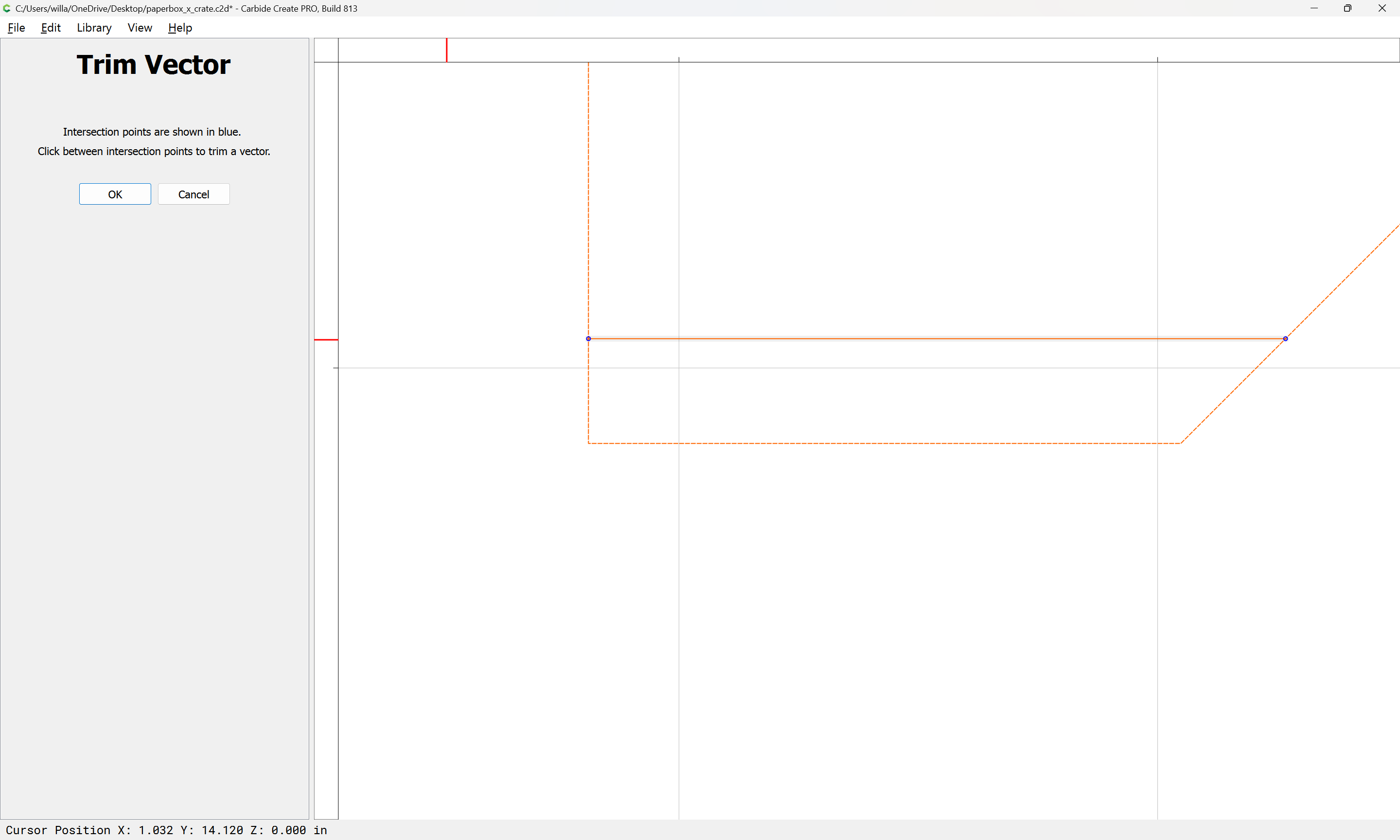
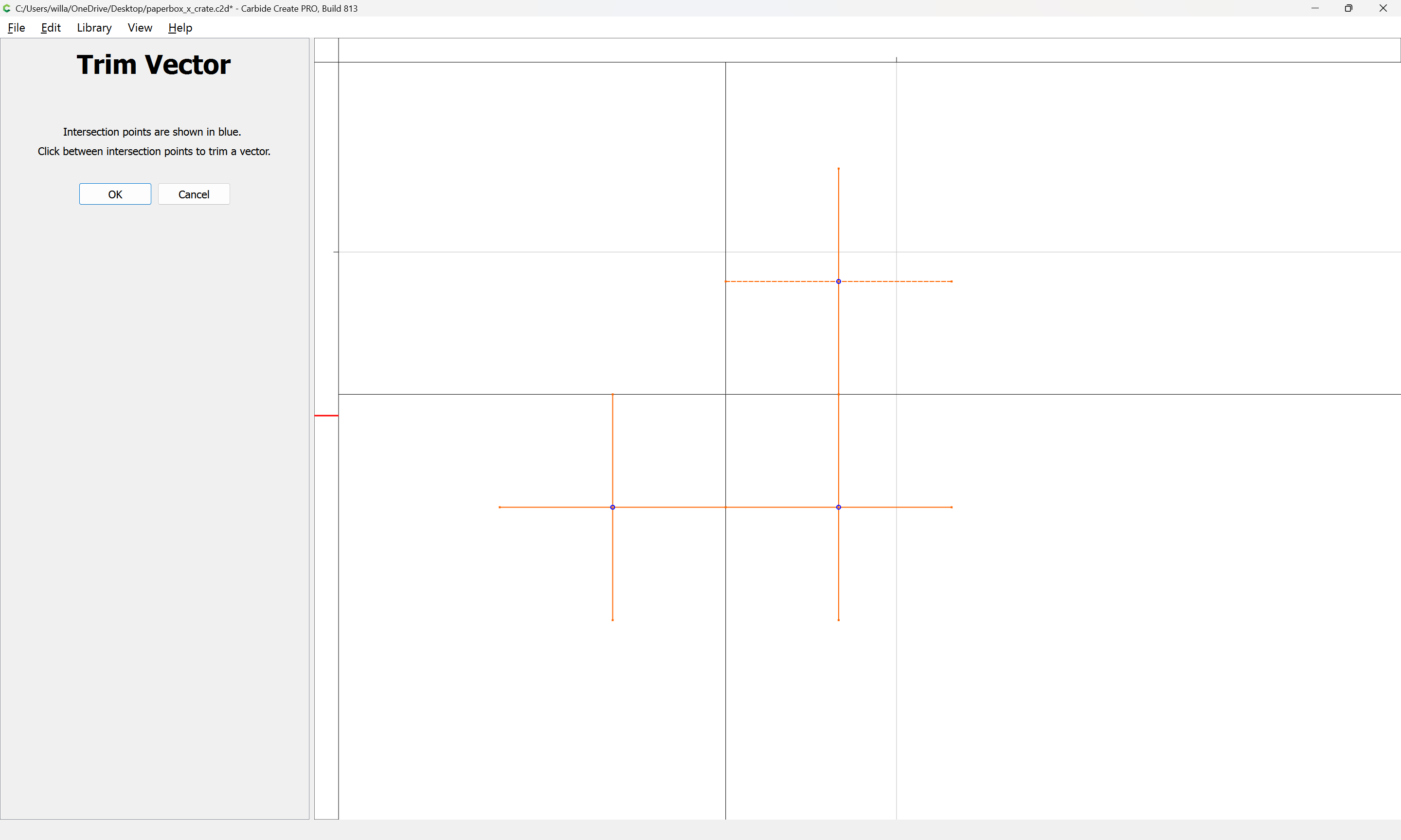
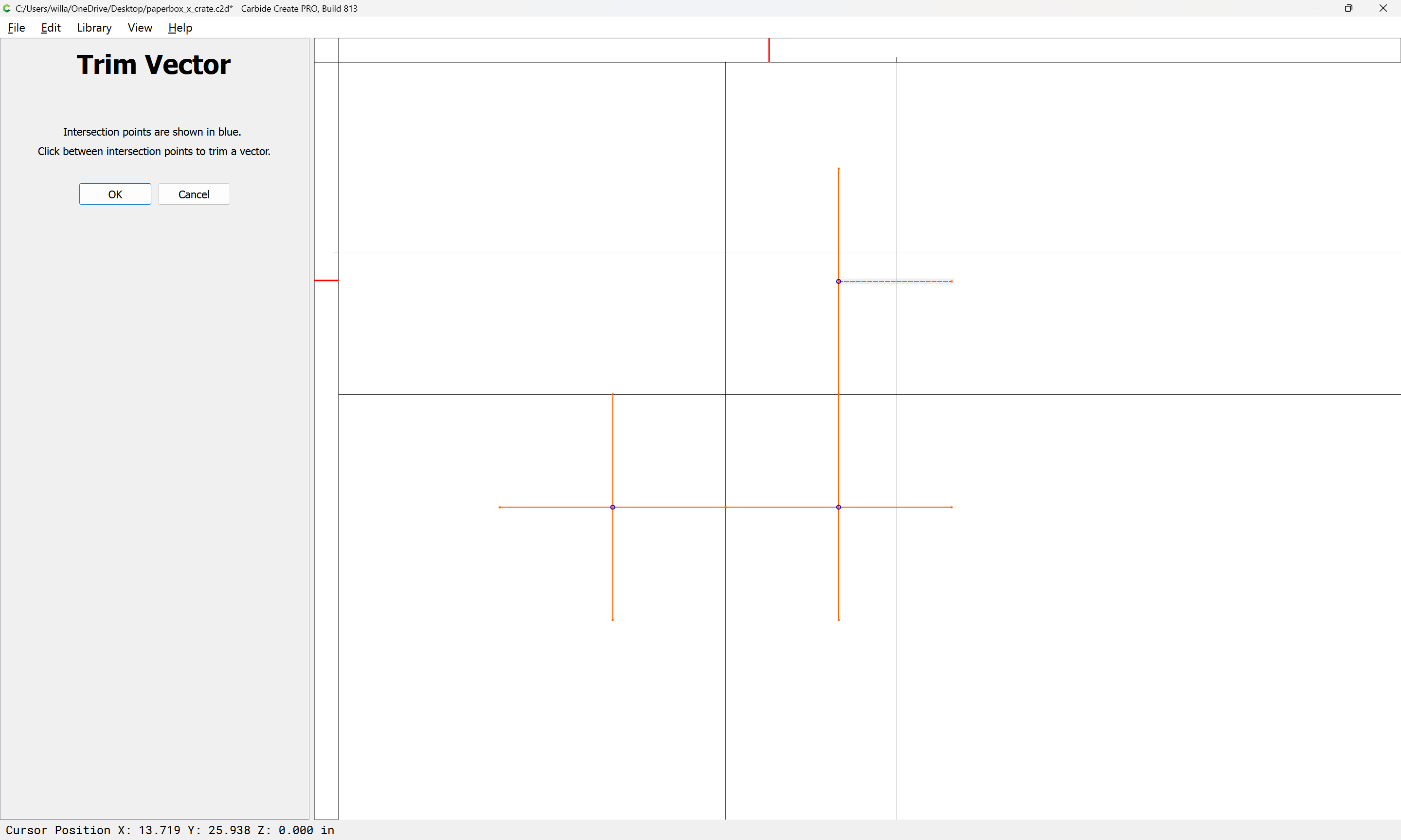
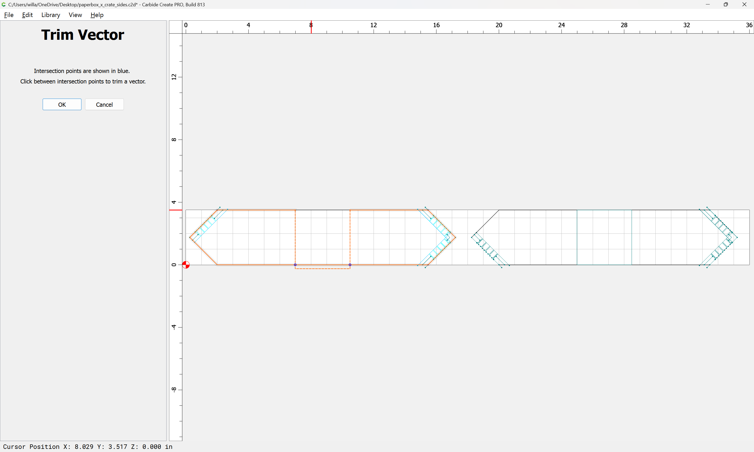
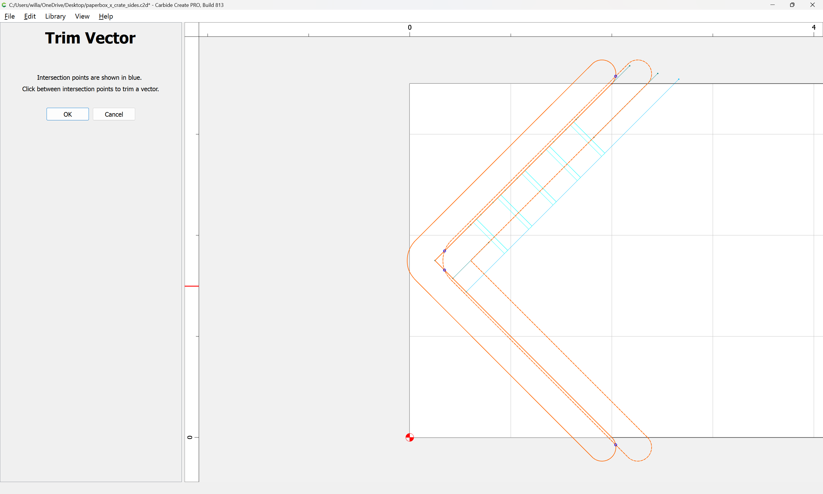
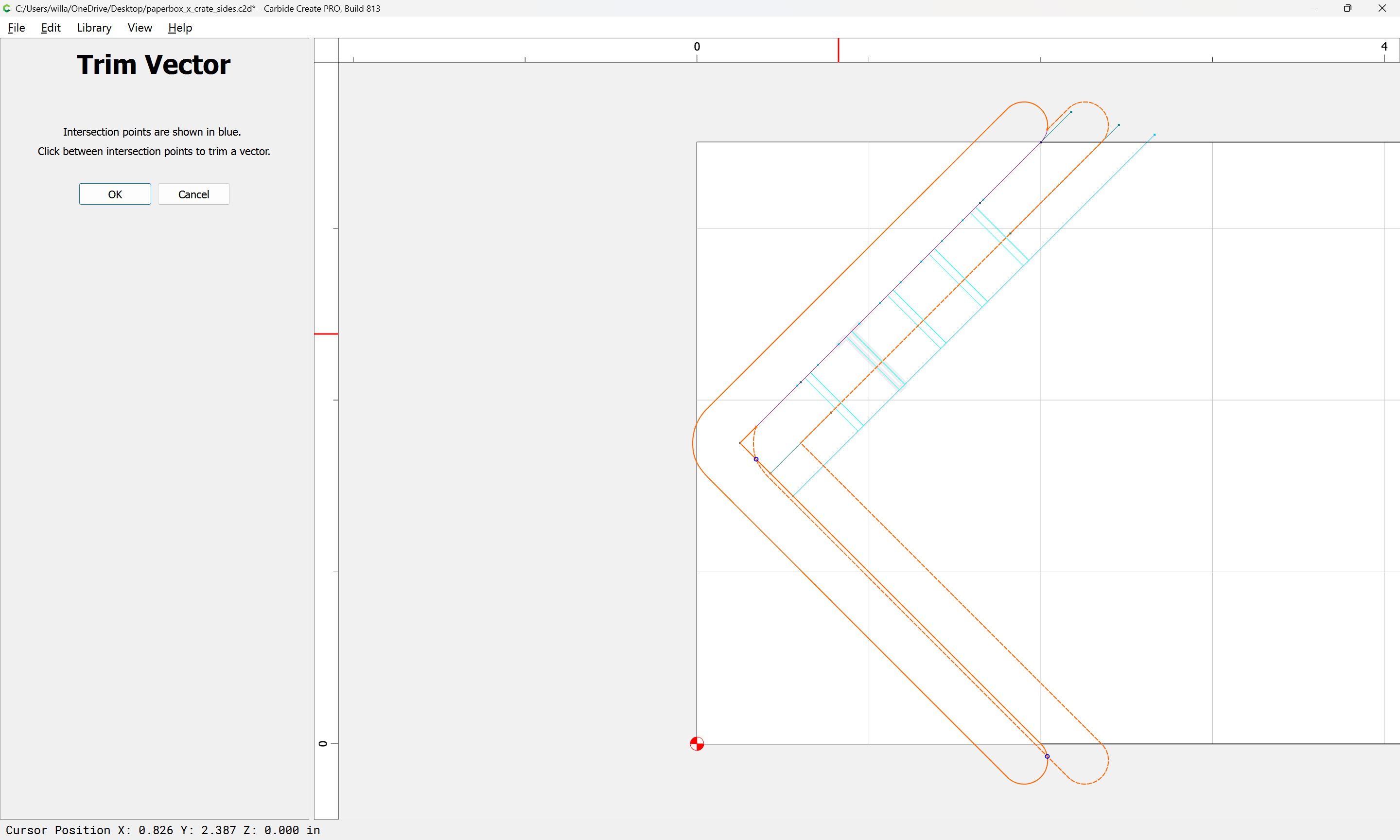
and use Trim Vectors to reduce this to just what is needed:
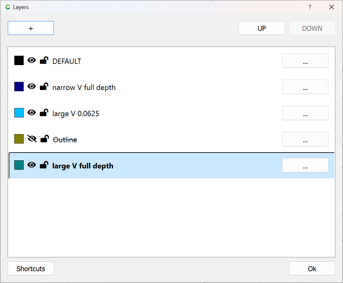
Note that a new layer will be necessary:
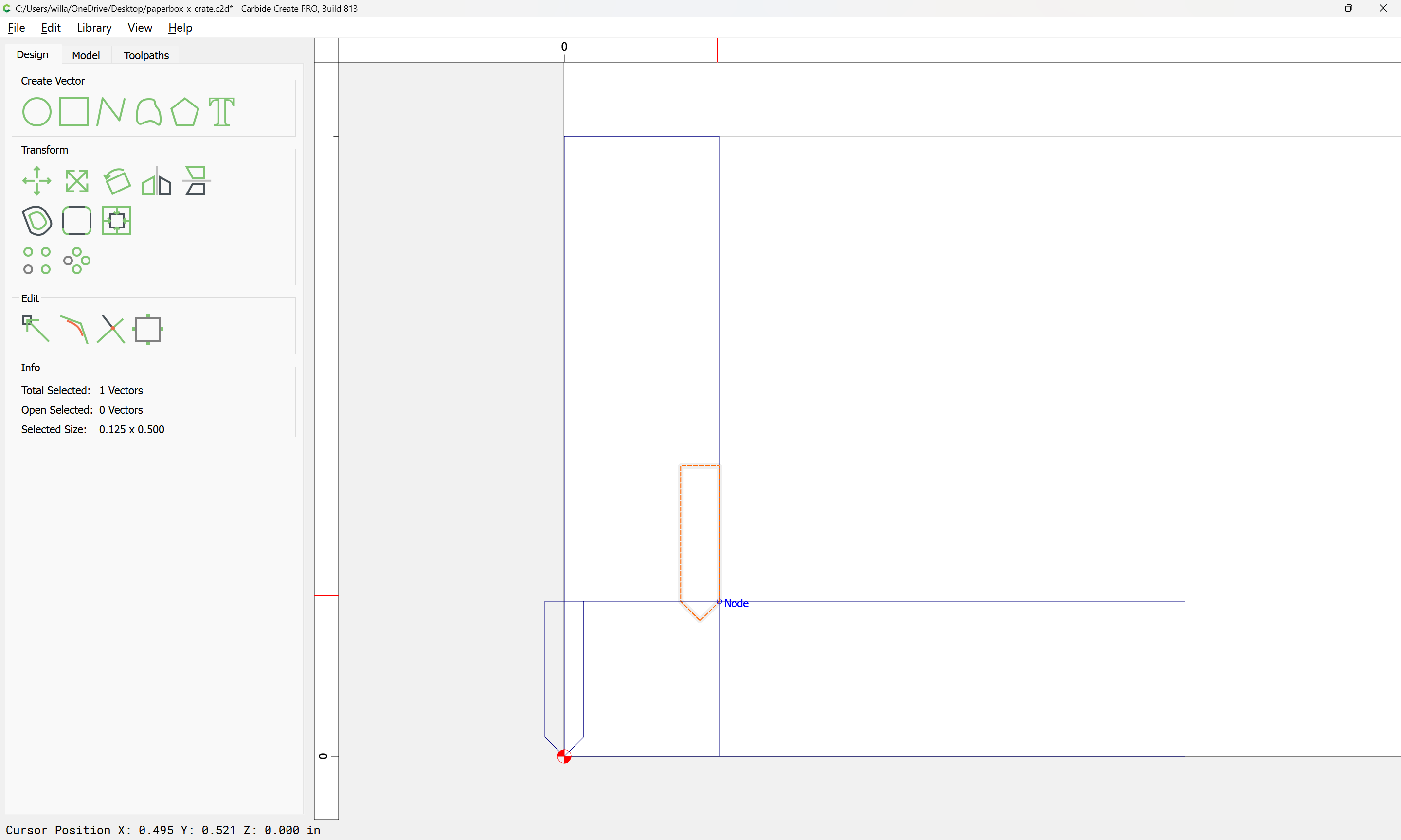
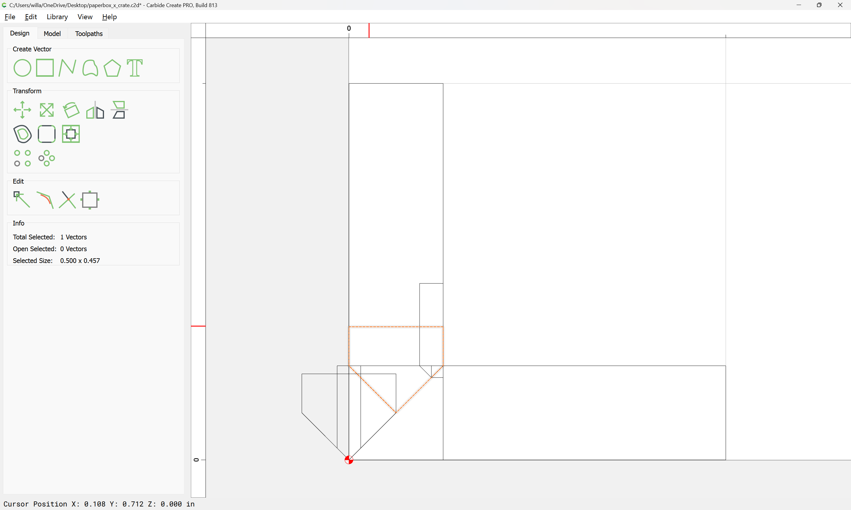
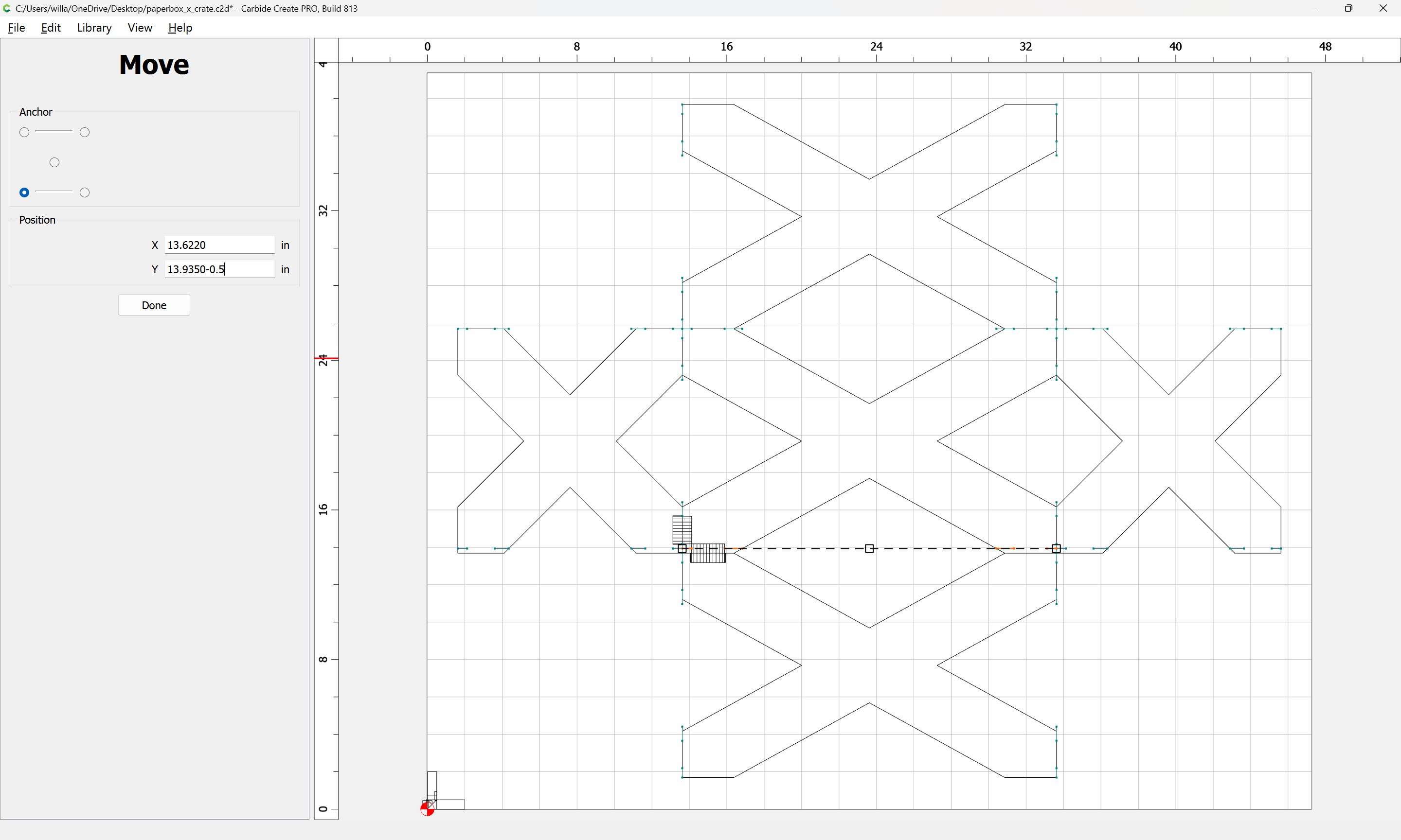
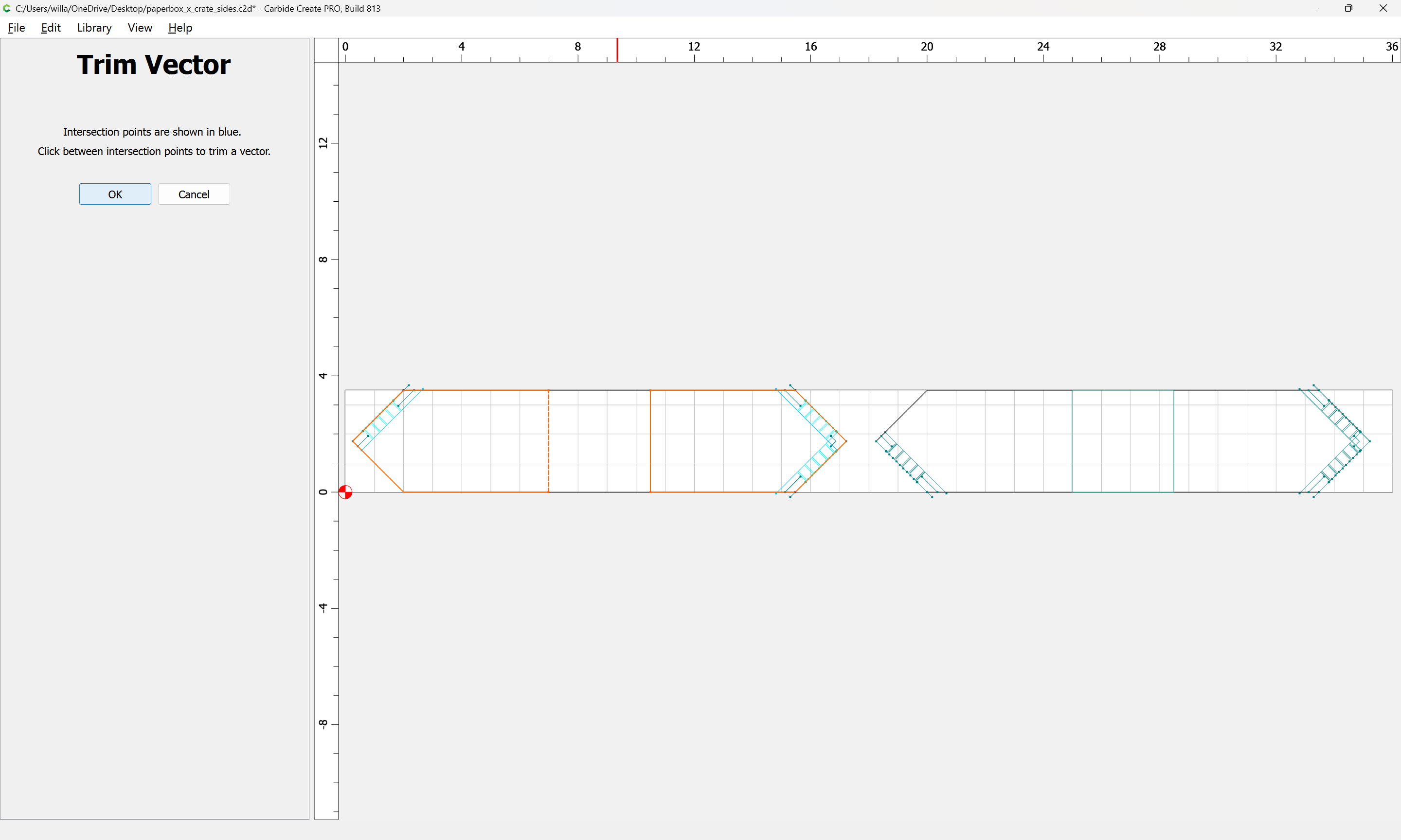
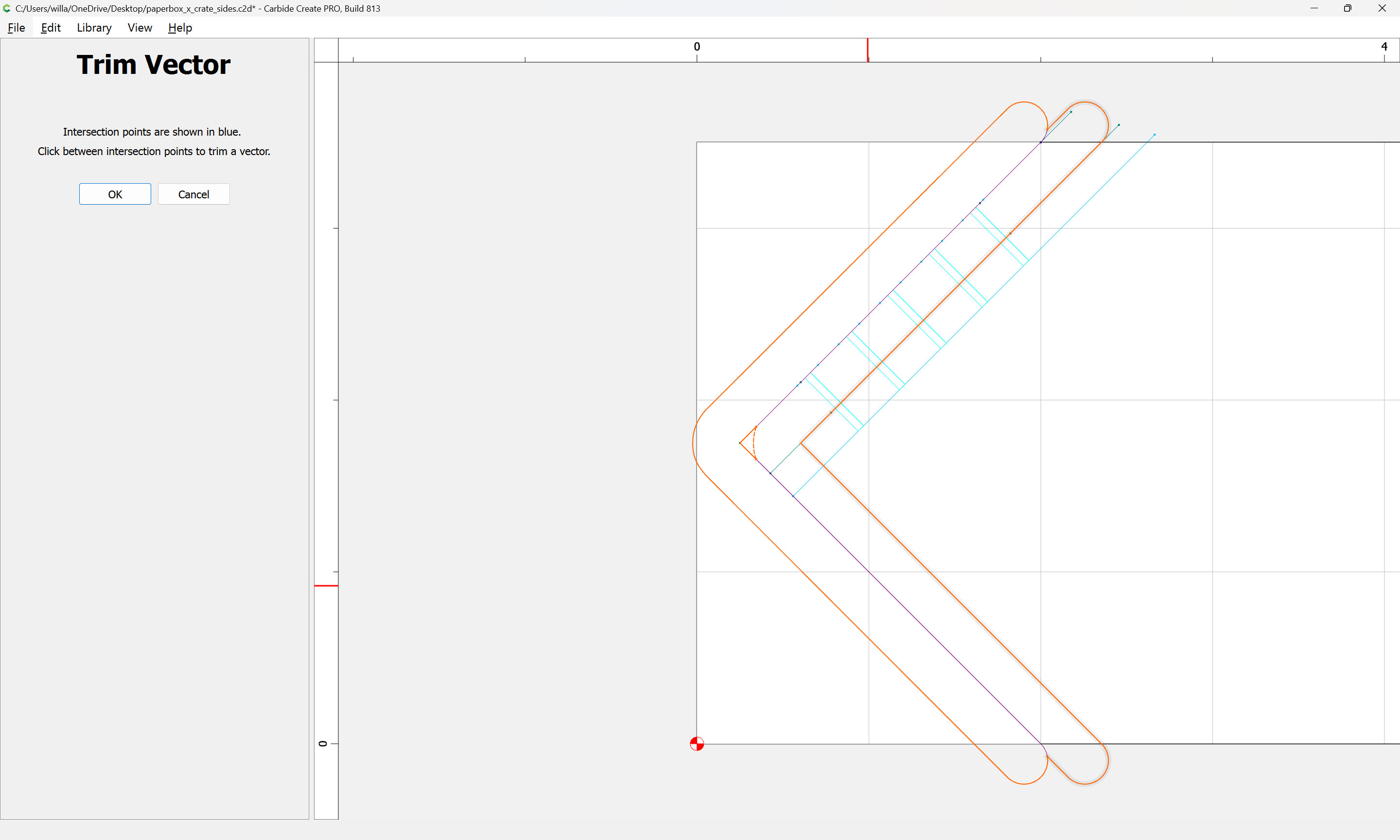
A further consideration is that because of the angle, the tool will not cut as far as-is necessary:
and it will be necessary to extend the line sufficiently to ensure that the cut is compleat.
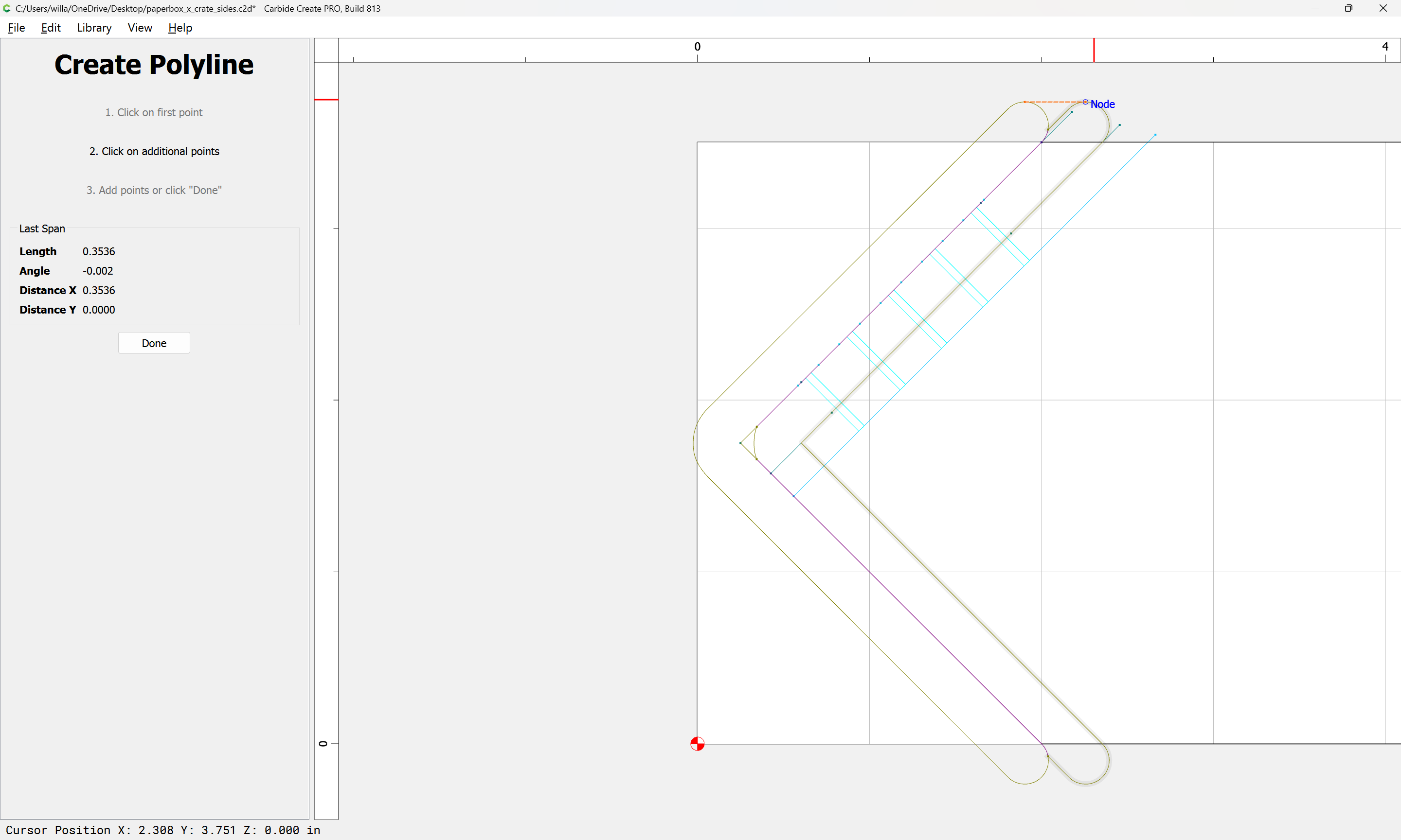
One way to do this would be to draw a suitably wide rectangle and get the Boolean intersection and then draw a line across the top:
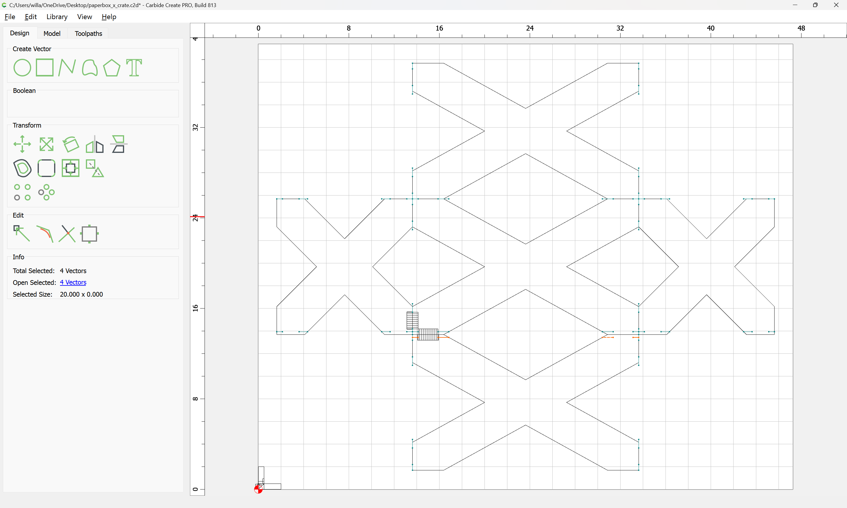
Reposition it, and delete the original line and the added geometry:
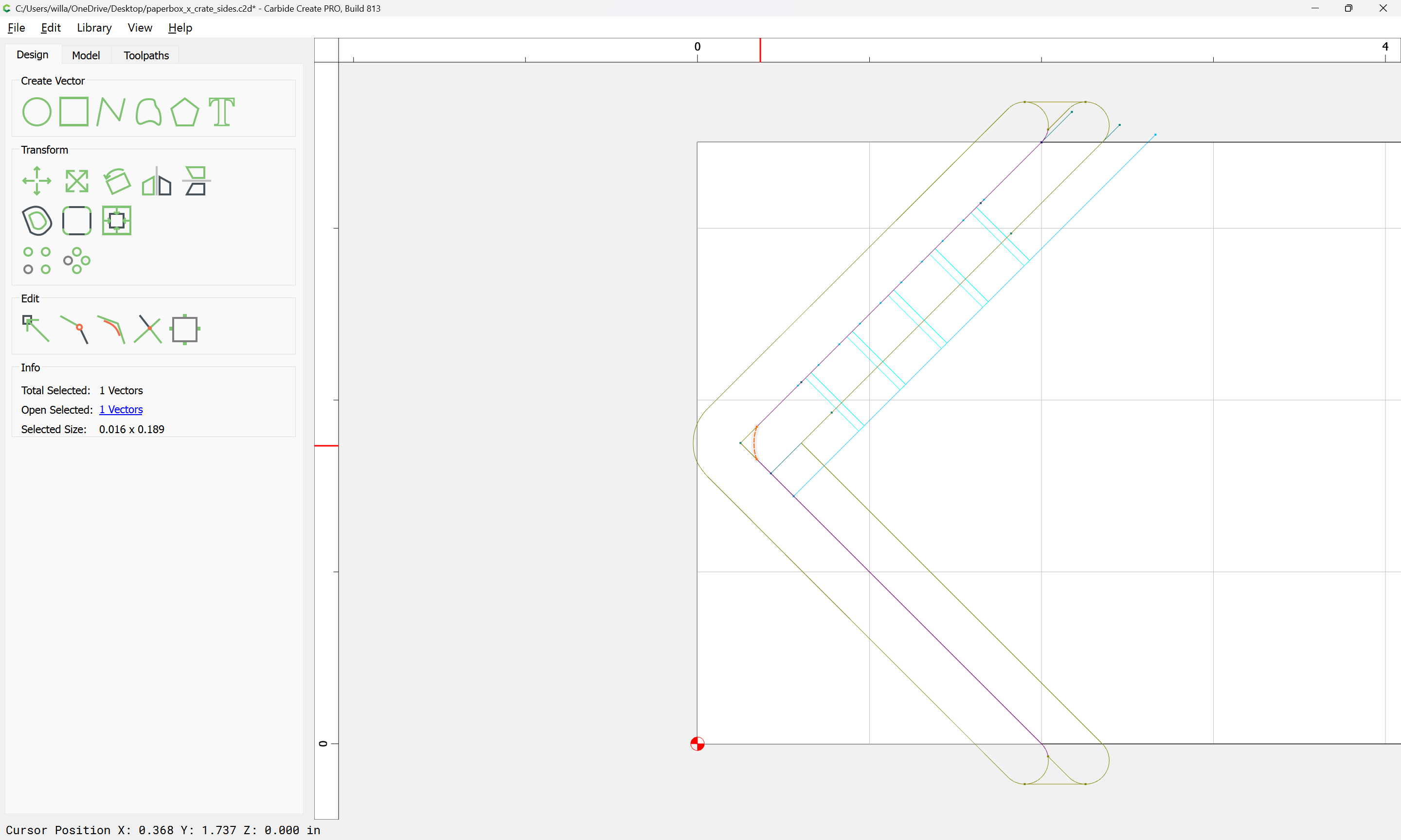
Assign the toolpath to the layer:
and repeat this for each other edge which must be joined…
WillAdams
February 2, 2025, 3:08am
5
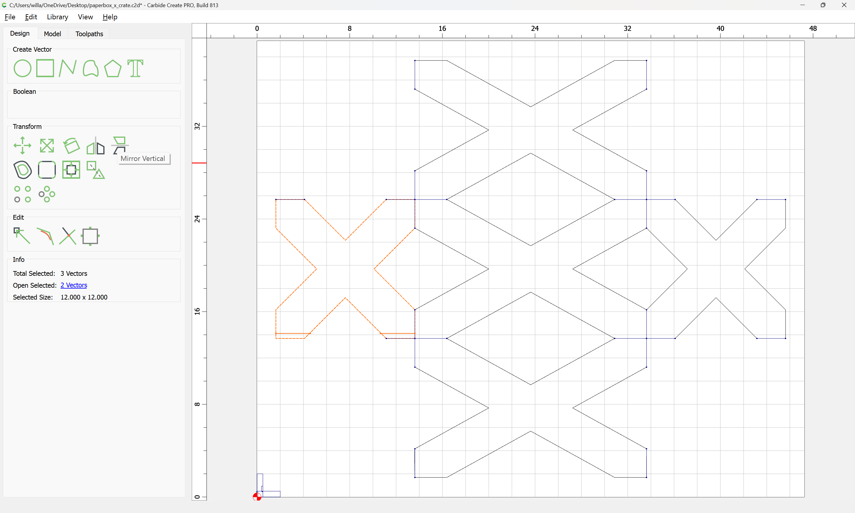
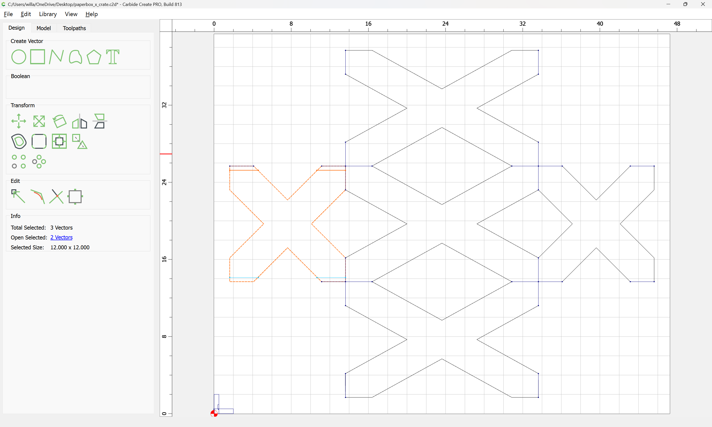
The duplication, as most are, is easily done by copy-pasting and judicious use of “Mirror Horizontal/Vertical”:
WillAdams
February 2, 2025, 2:21pm
6
Adding geometry to cut out the surrounding area helps to make things a bit clearer:
Next step is to cut the full 90 degree blind miters at the end of each joint…
1 Like
WillAdams
February 2, 2025, 3:51pm
7
There are three possible ends to each joint:
visible end at 90 degree cut (relative to joint)
visible end at angled cut
invisible end where 3 parts are joined
The first and last should work with a cut which is the board thickness measuring from the end, but the angle will require the same sort of treatment as the upper cuts.
First, a new layer:
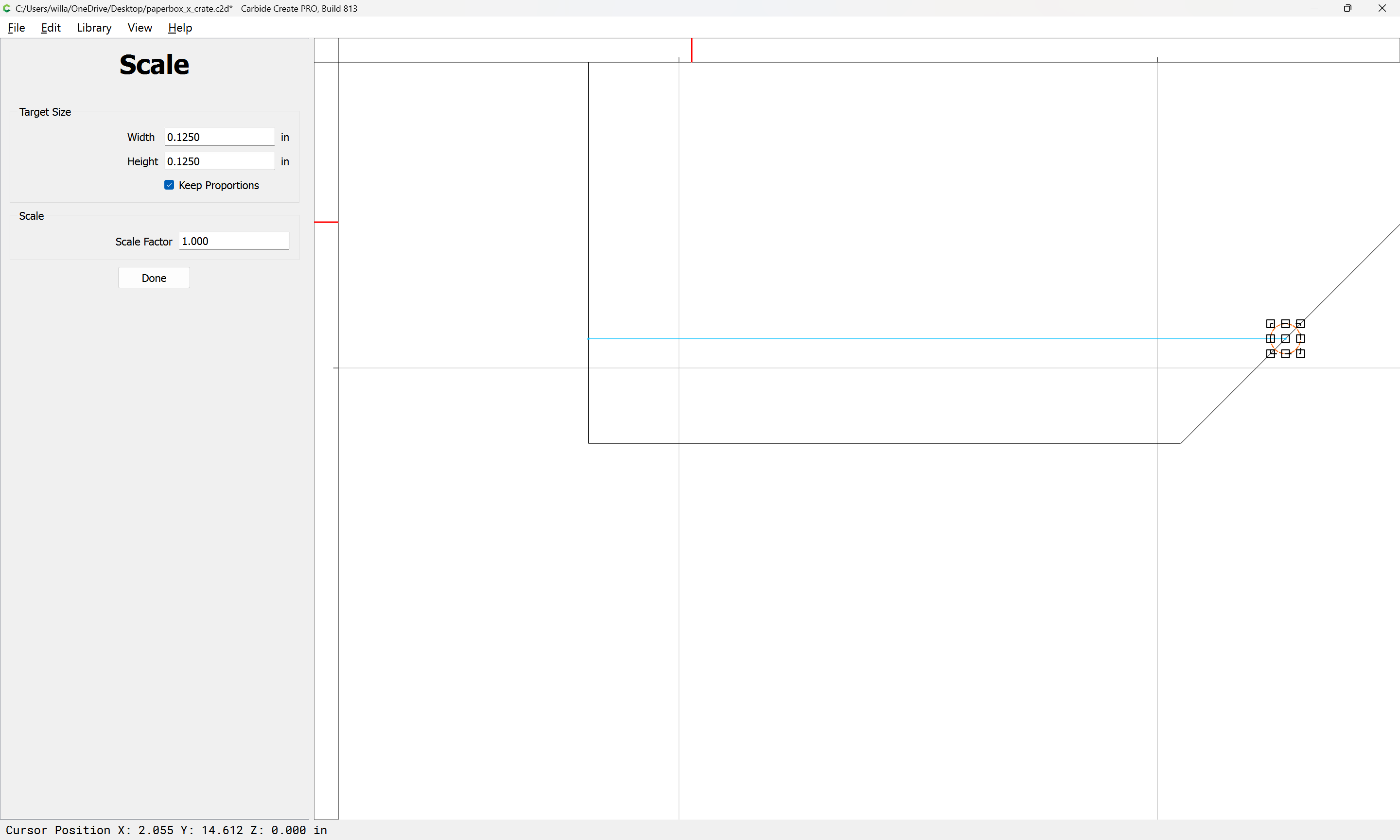
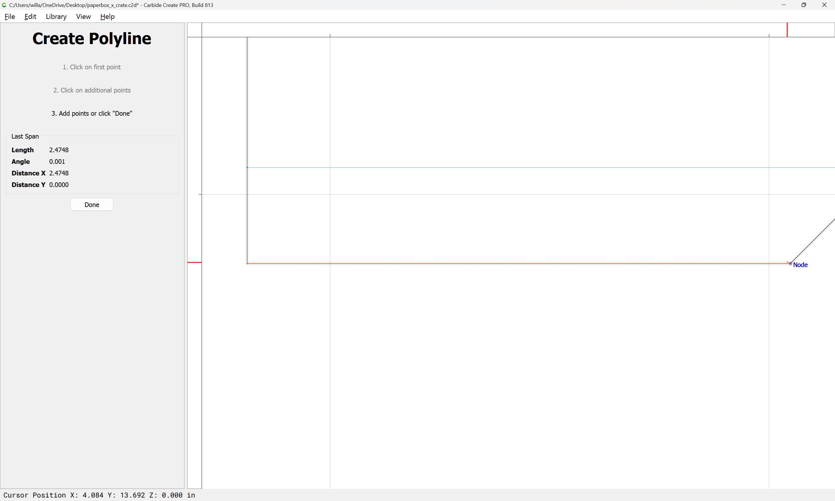
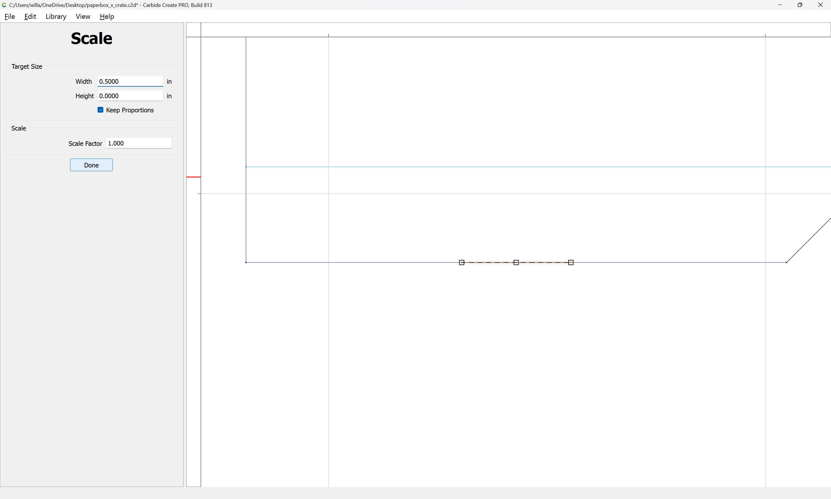
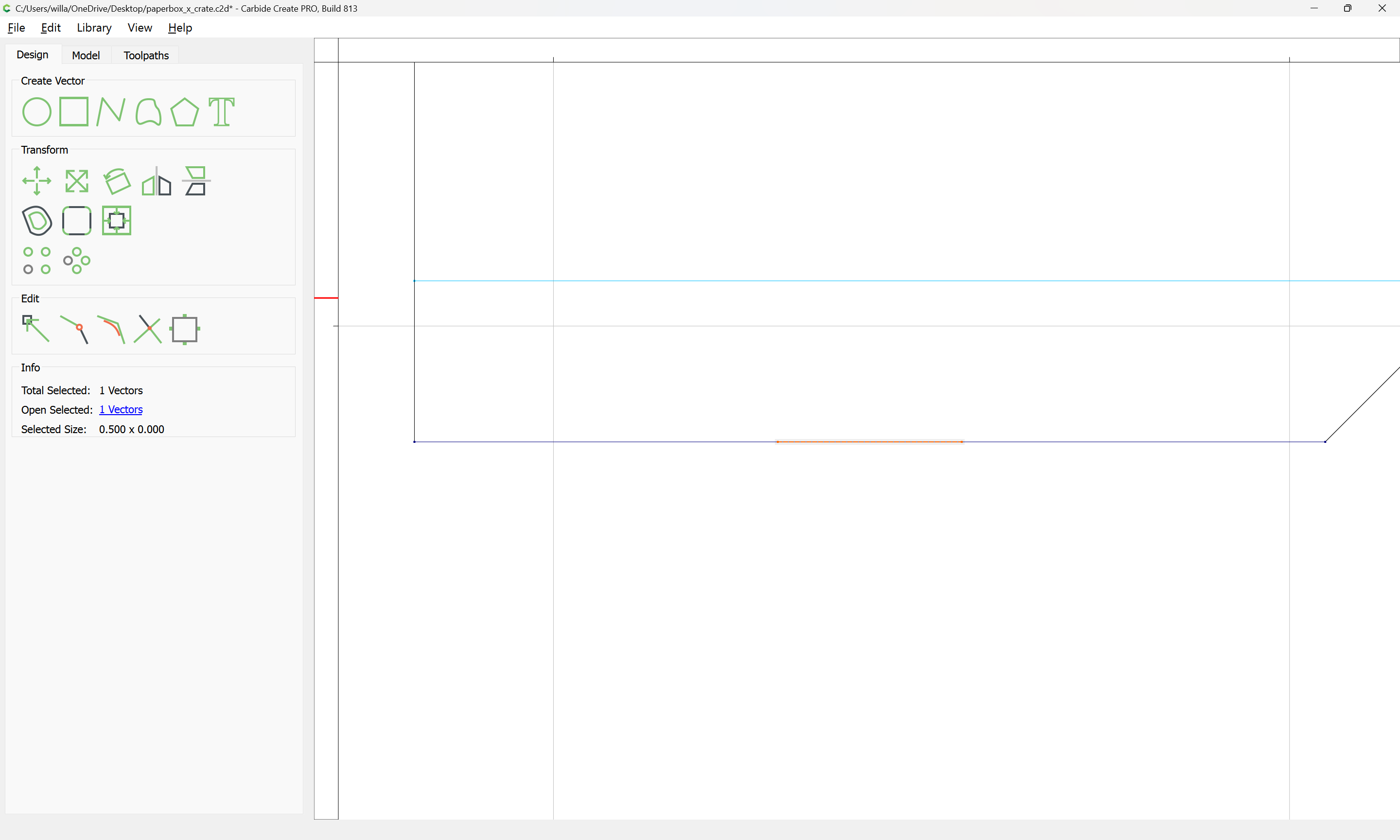
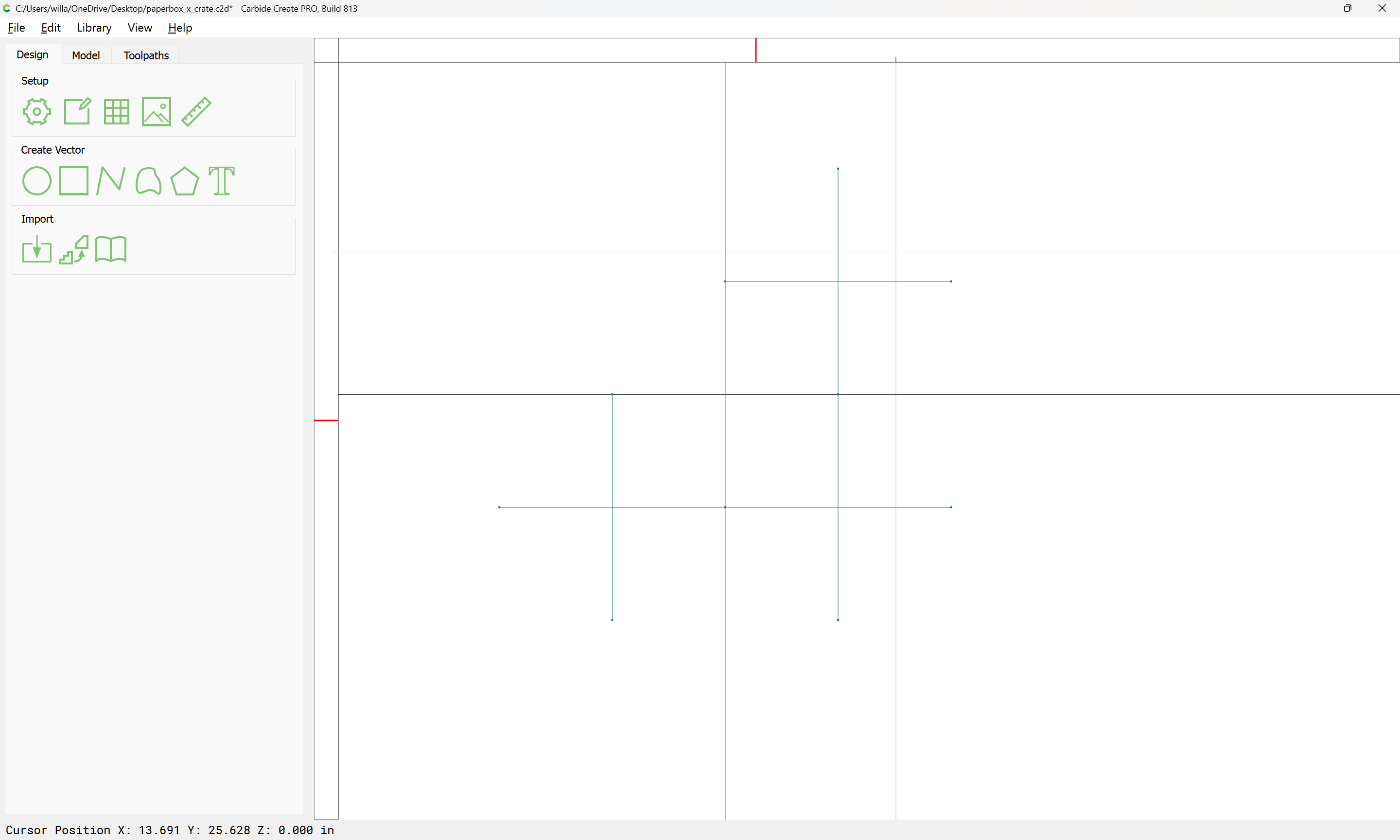
Then draw a line:
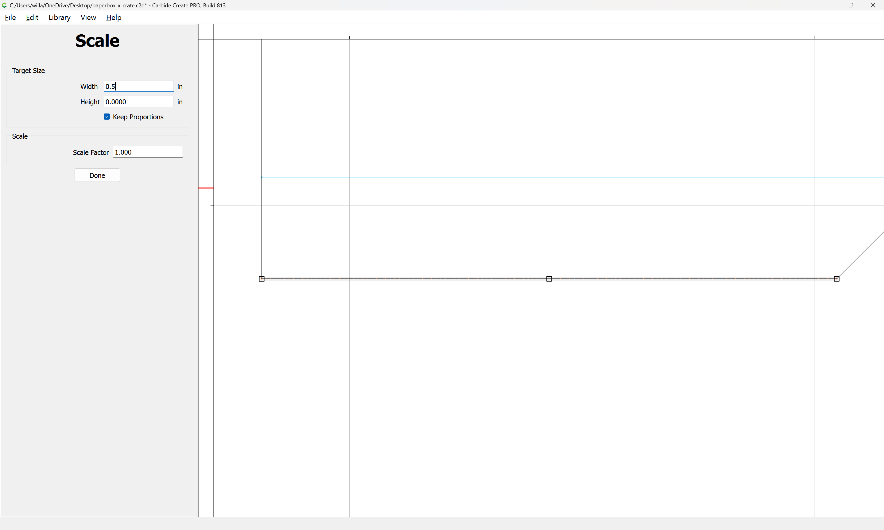
and scale it to the desired dimension:
Done
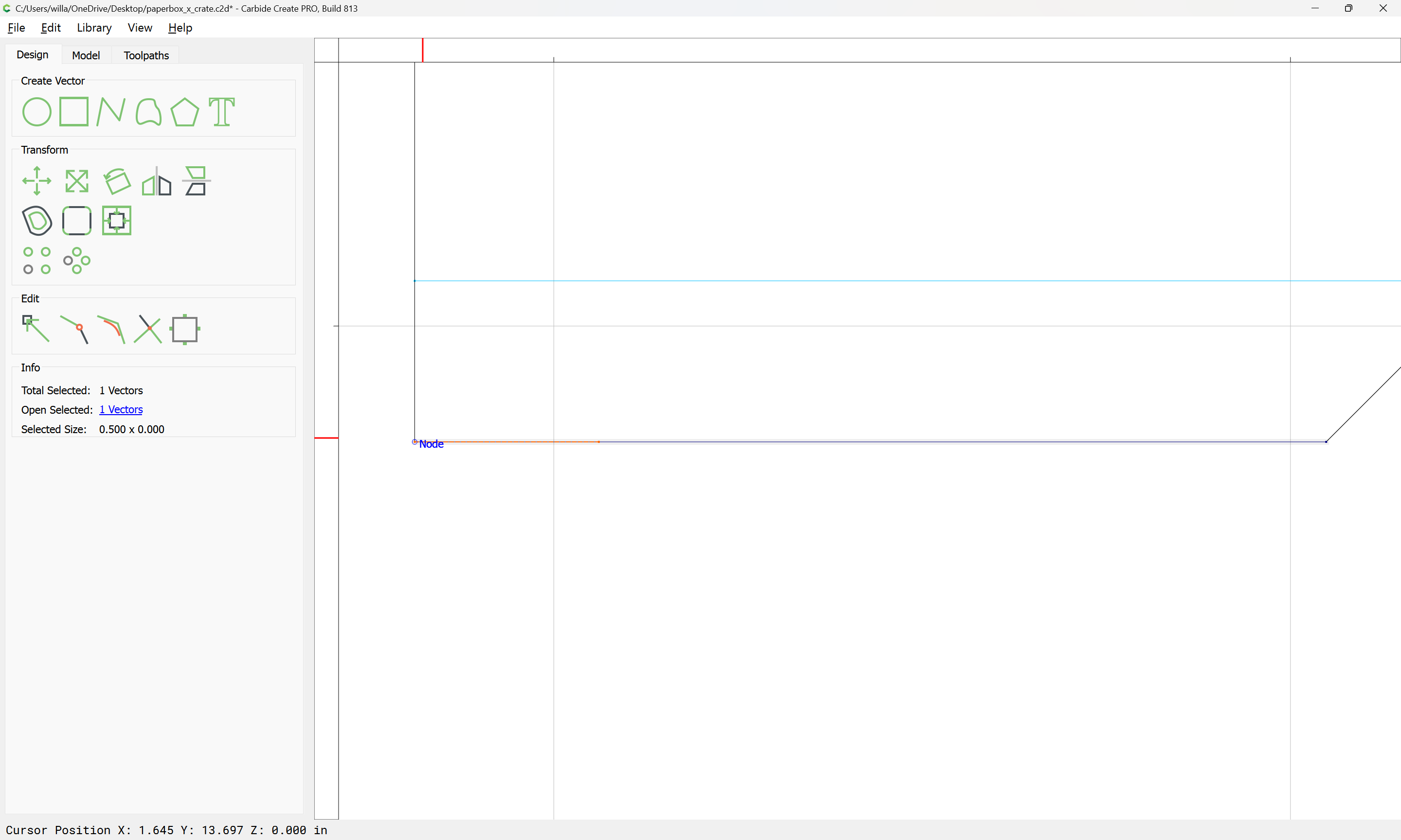
and reposition it:
Copy-paste and reposition for the other end:
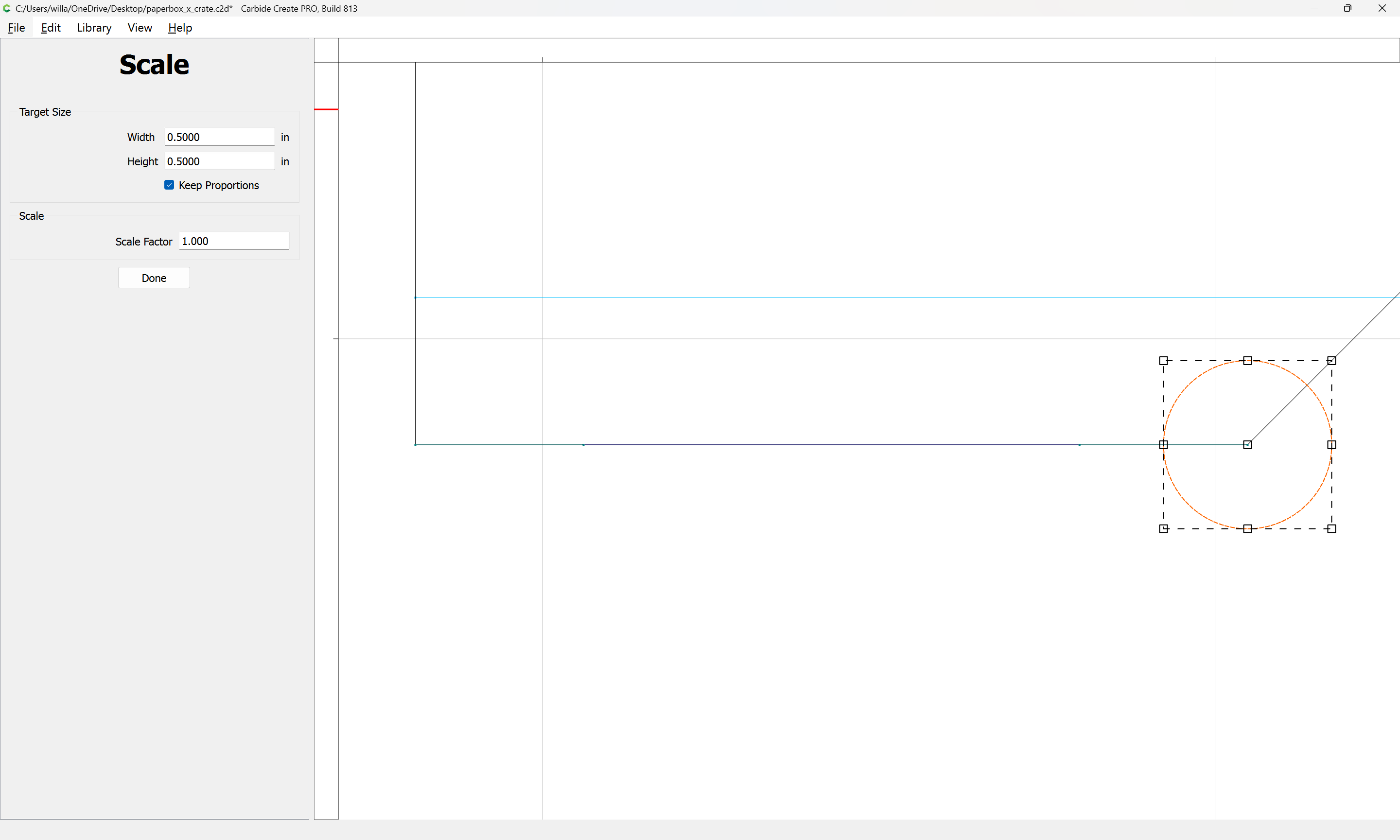
Then draw a circle centered at that end:
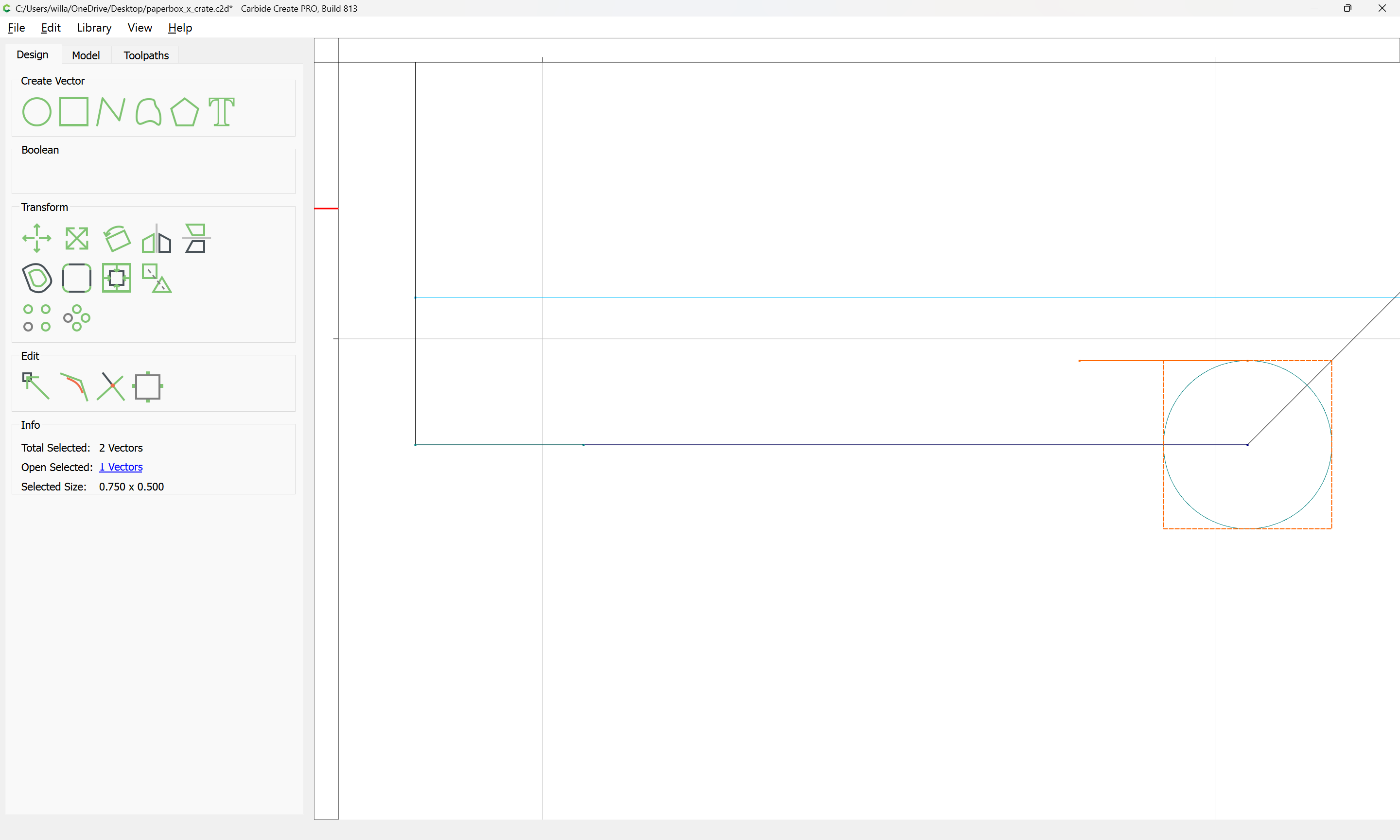
and draw a square to get the required dimension:
Resizing it:
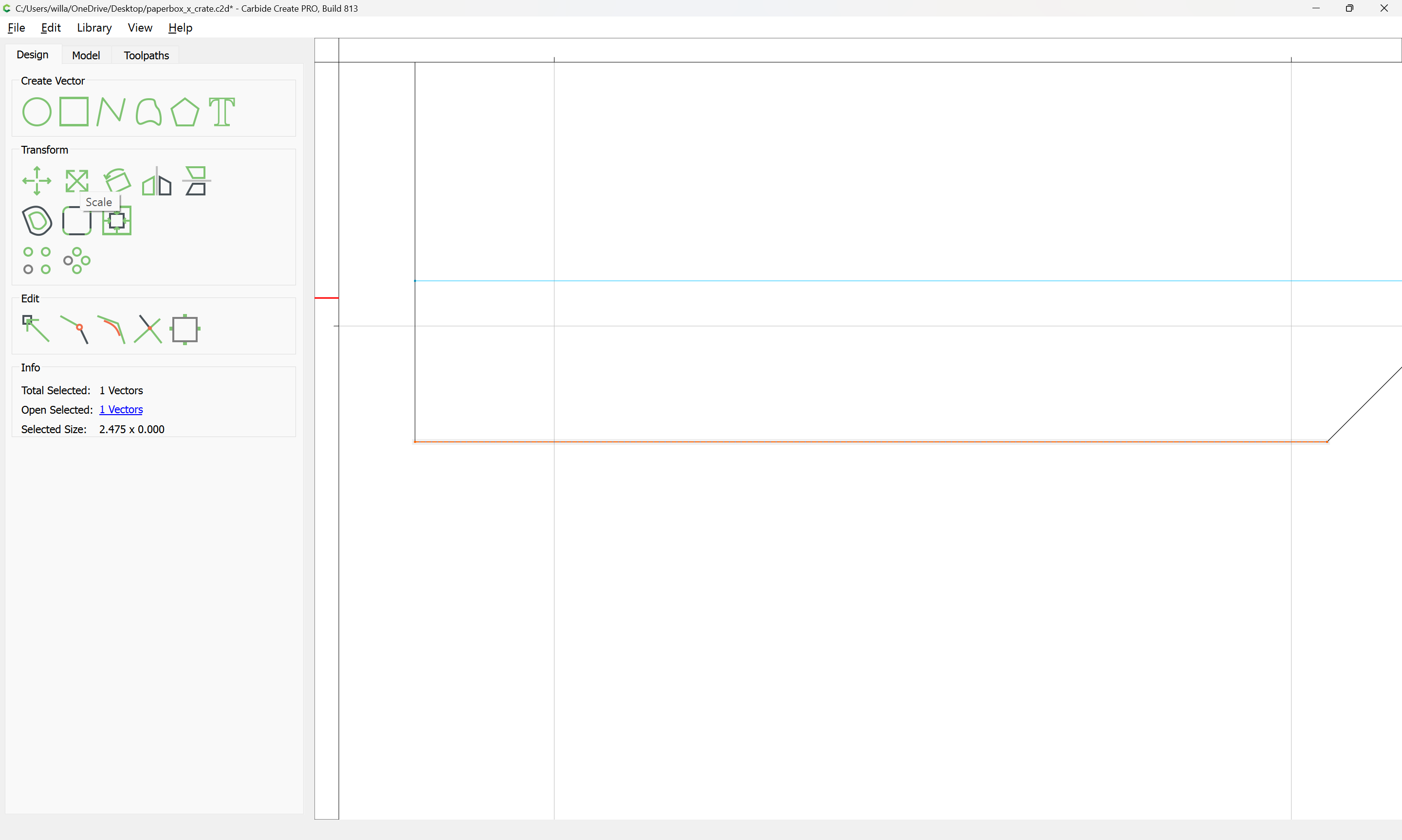
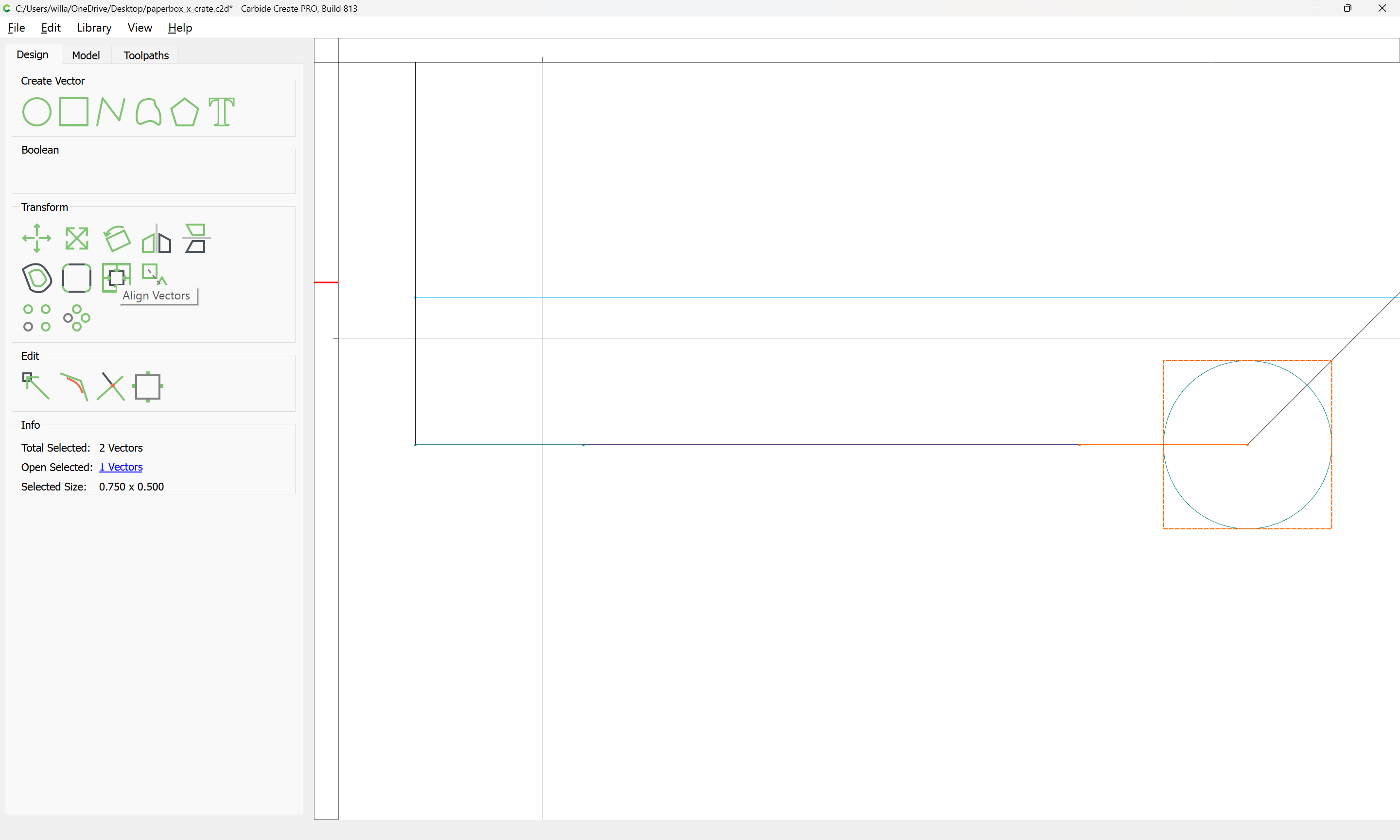
Then select it and the line:
and use Align Vectors to reposition:
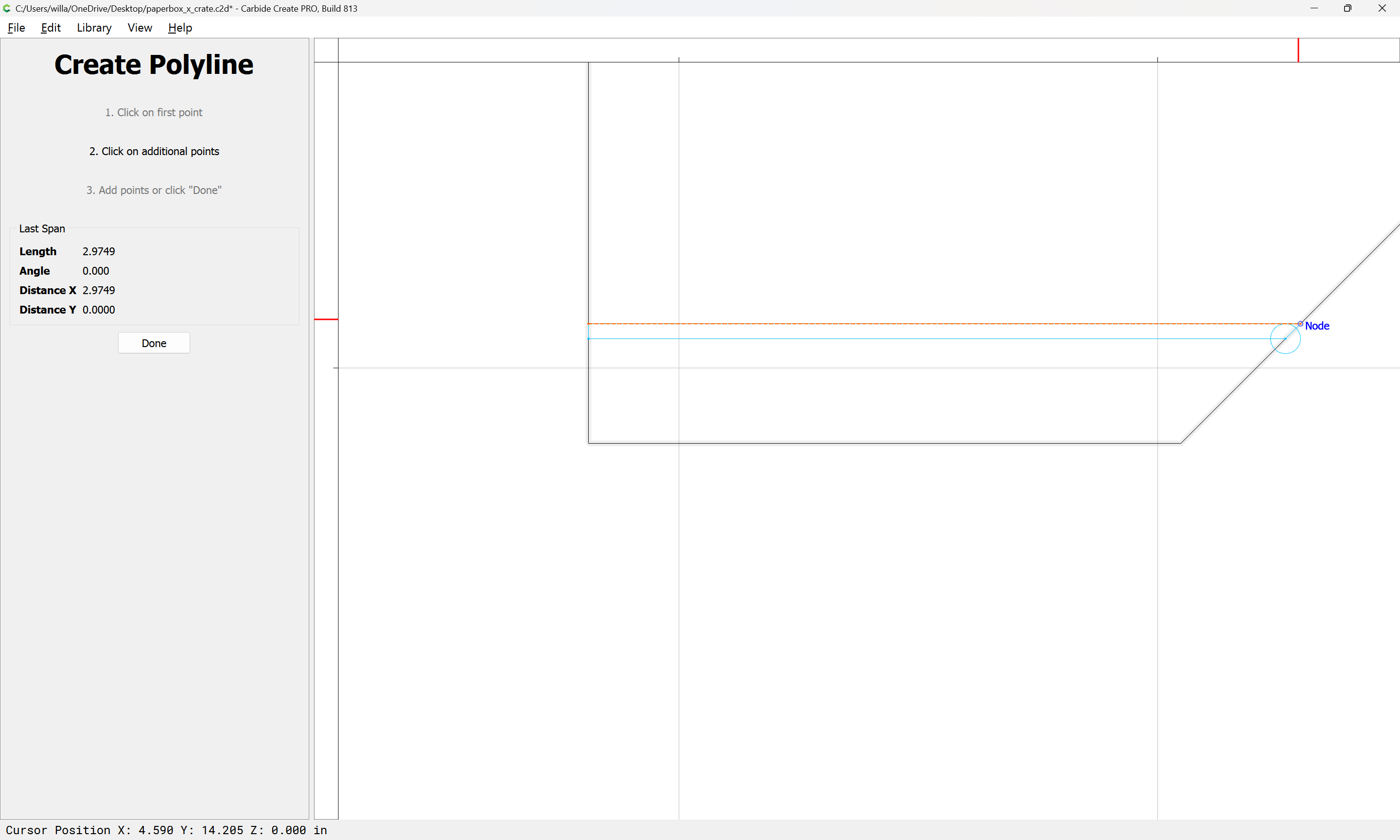
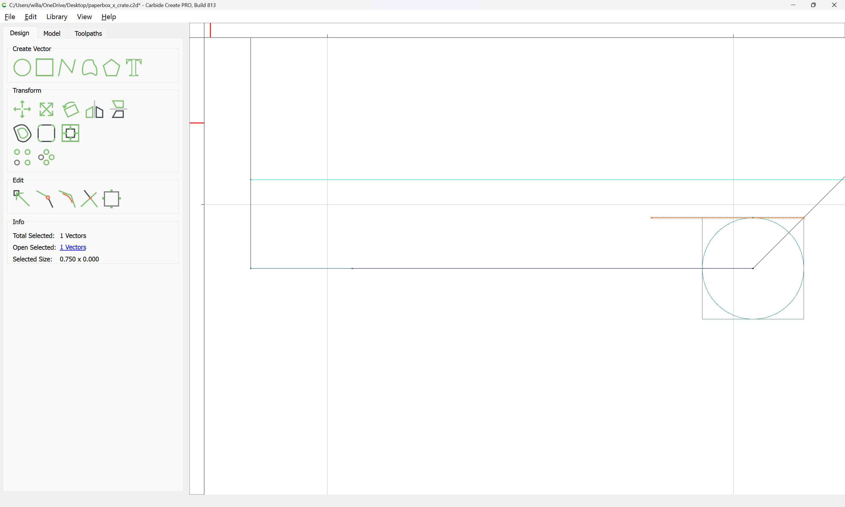
Then draw a line of the desired length:
Done
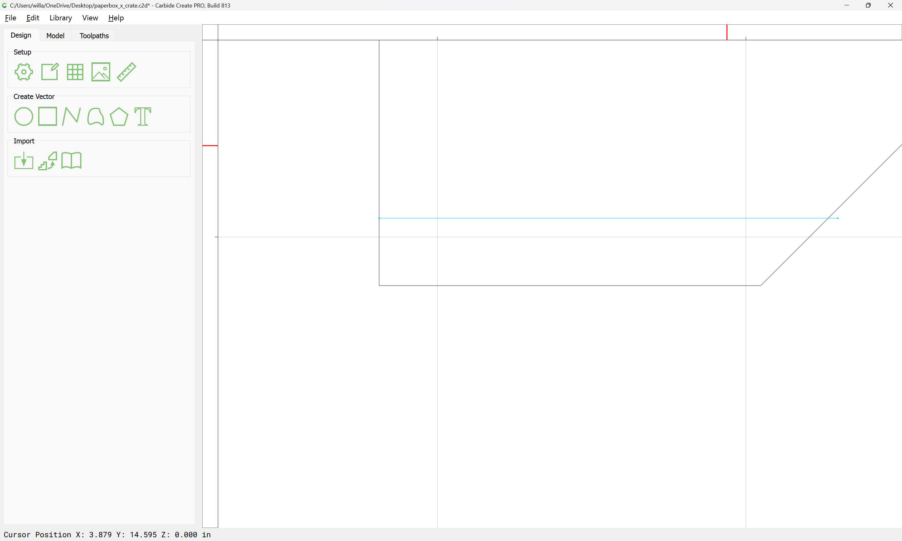
Reposition things and delete what is not wanted:
copy-paste this to where it is needed, using mirroring where appropriate to speed things up:
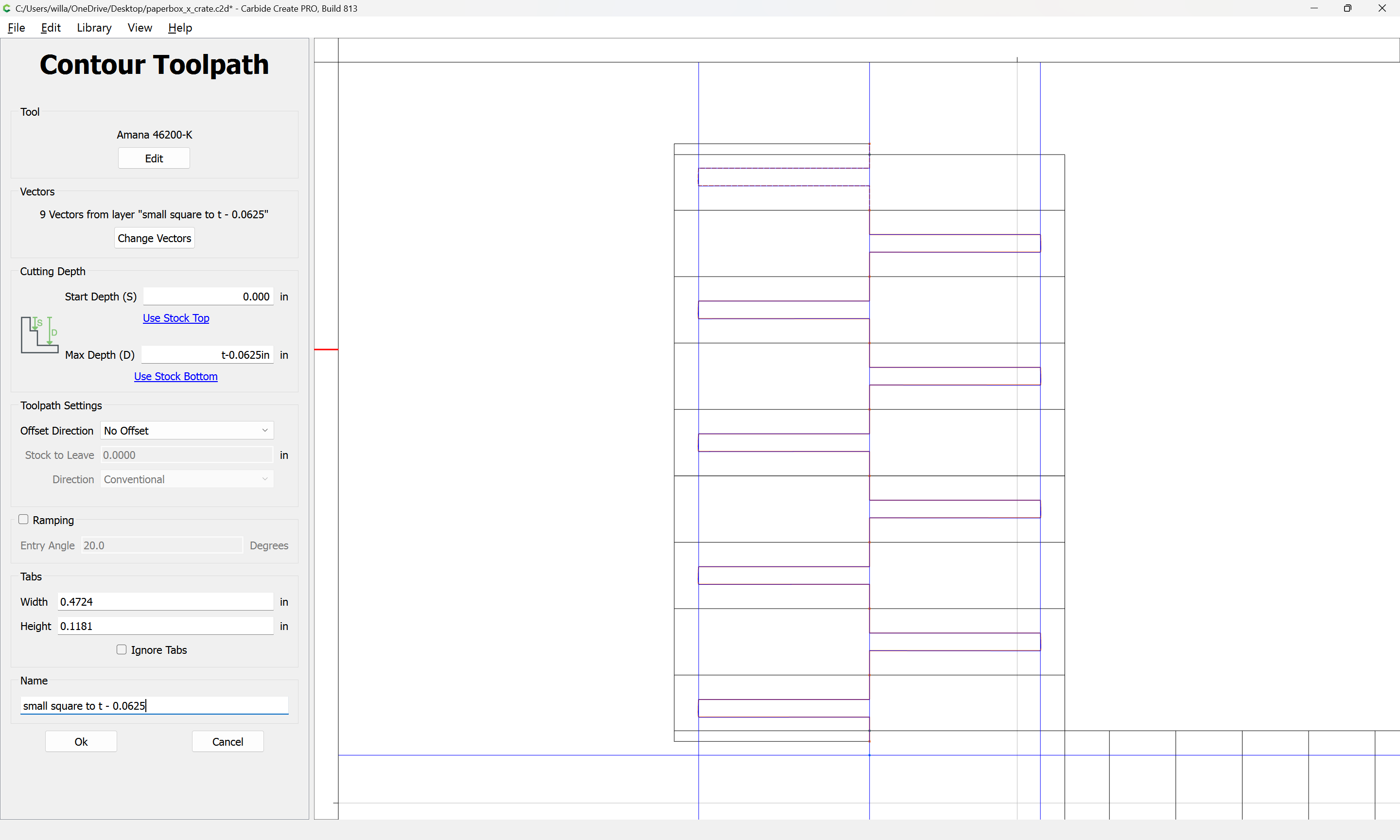
then set up a toolpath:
which helps make things a bit clearer:
Draw in similar geometry for the other joints…
WillAdams
February 2, 2025, 4:52pm
8
Which gets us to:
which makes it obvious where the pocket geometry needs to be drawn in.
To differentiate them, and to help with symmetry and to reduce parts count, it is helpful to consider that there are two options:
an odd number of recesses with an even number of box joint projections (fingers) in-between
an even number of recesses with an odd number of projections
If the ends and the back only have one set, and the top/bottom only have the other, then only the back parts will need to a mix of the twain.
Another consideration is how long the joint regions are. Measuring we get:
and
There should be a bit of give at the ends where if the joint moves into the area already cut by the V endmill it will not cause difficulties.
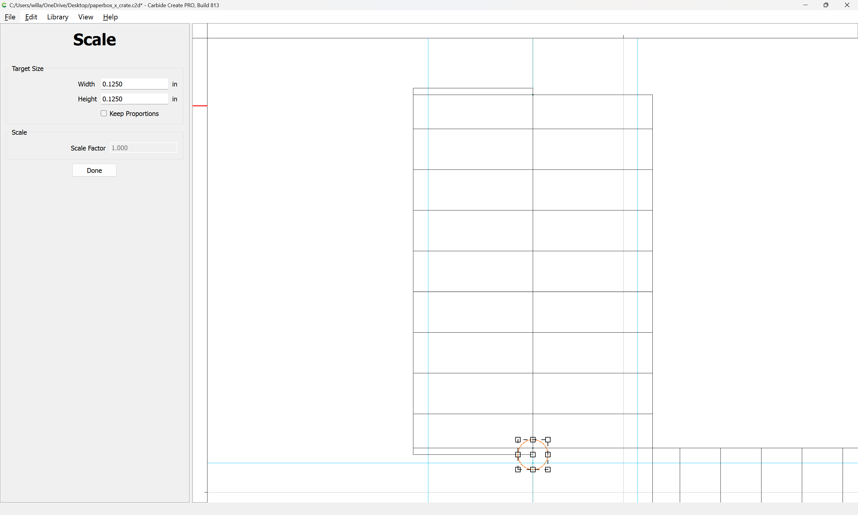
Looking at the dimensions it looks as if 0.17" will work as a unit size:
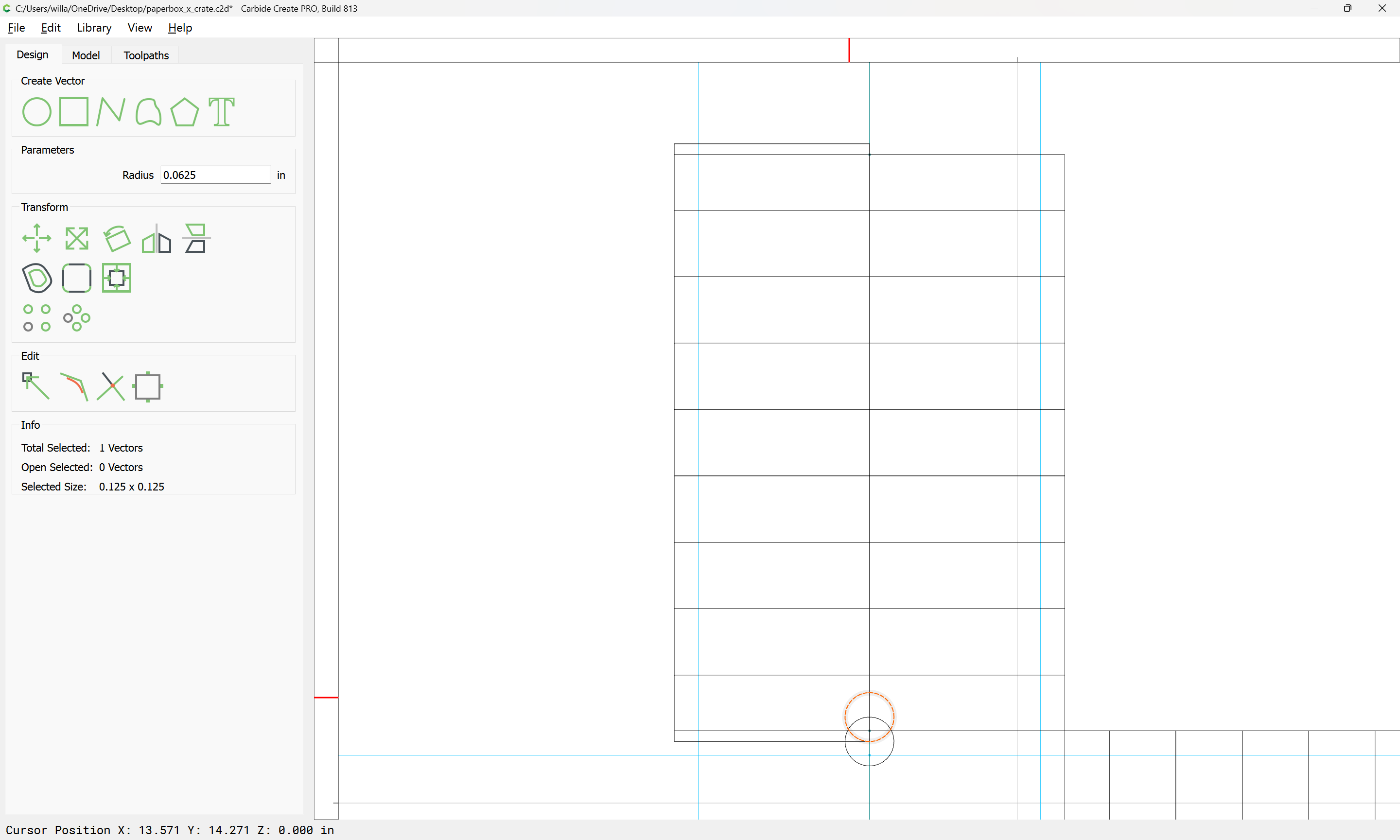
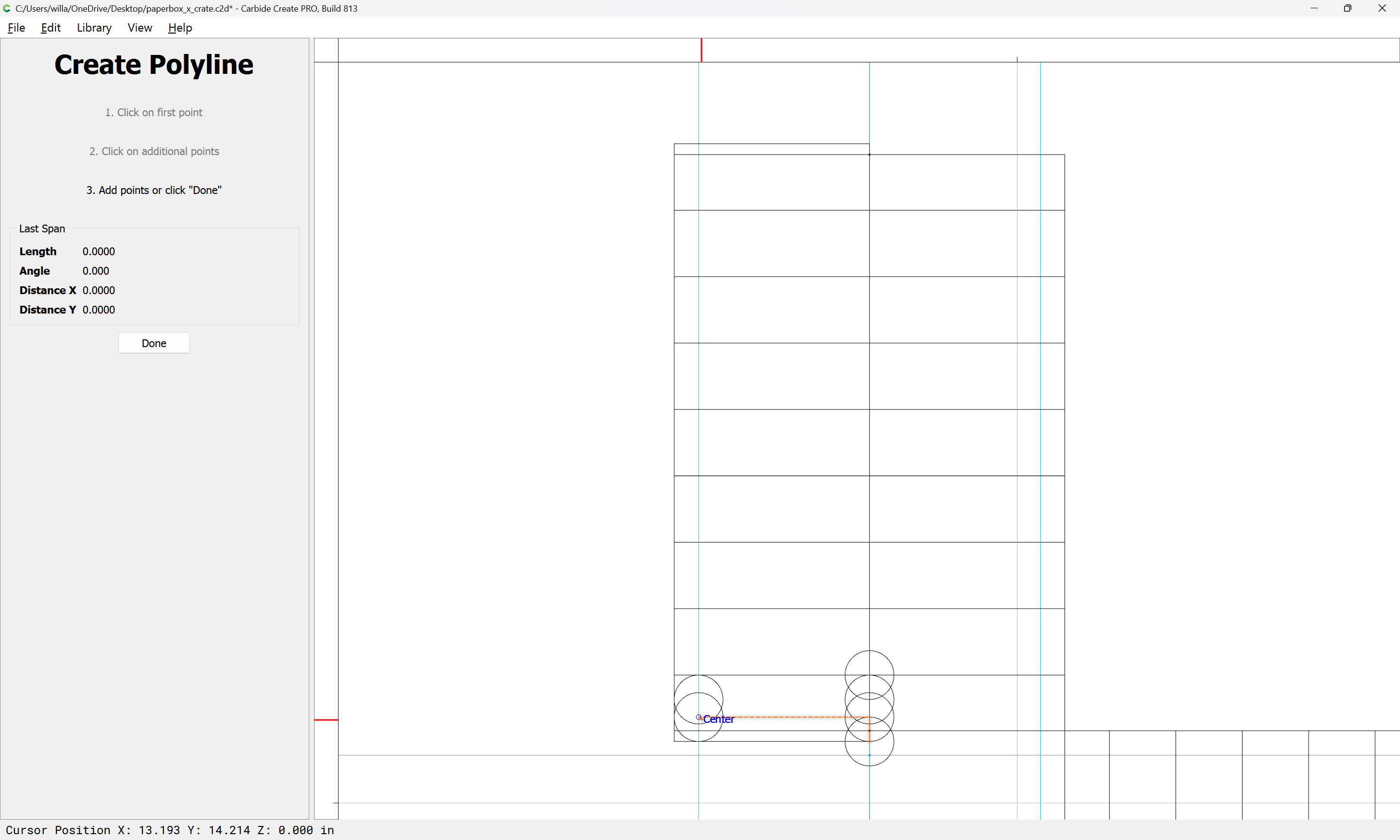
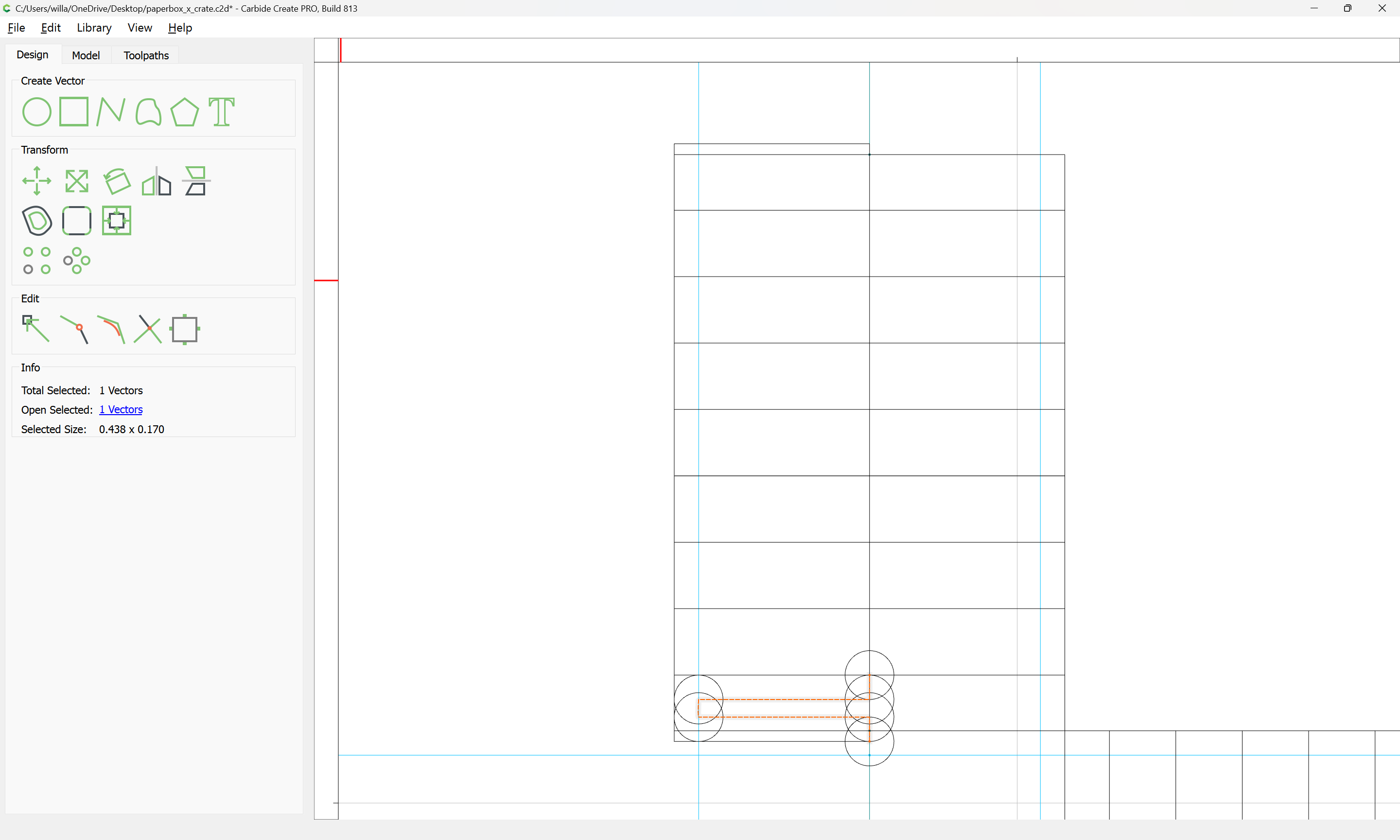
Visualizing/drawing the path is straight-forward if one draws a circle the diameter of the tool which will be used:
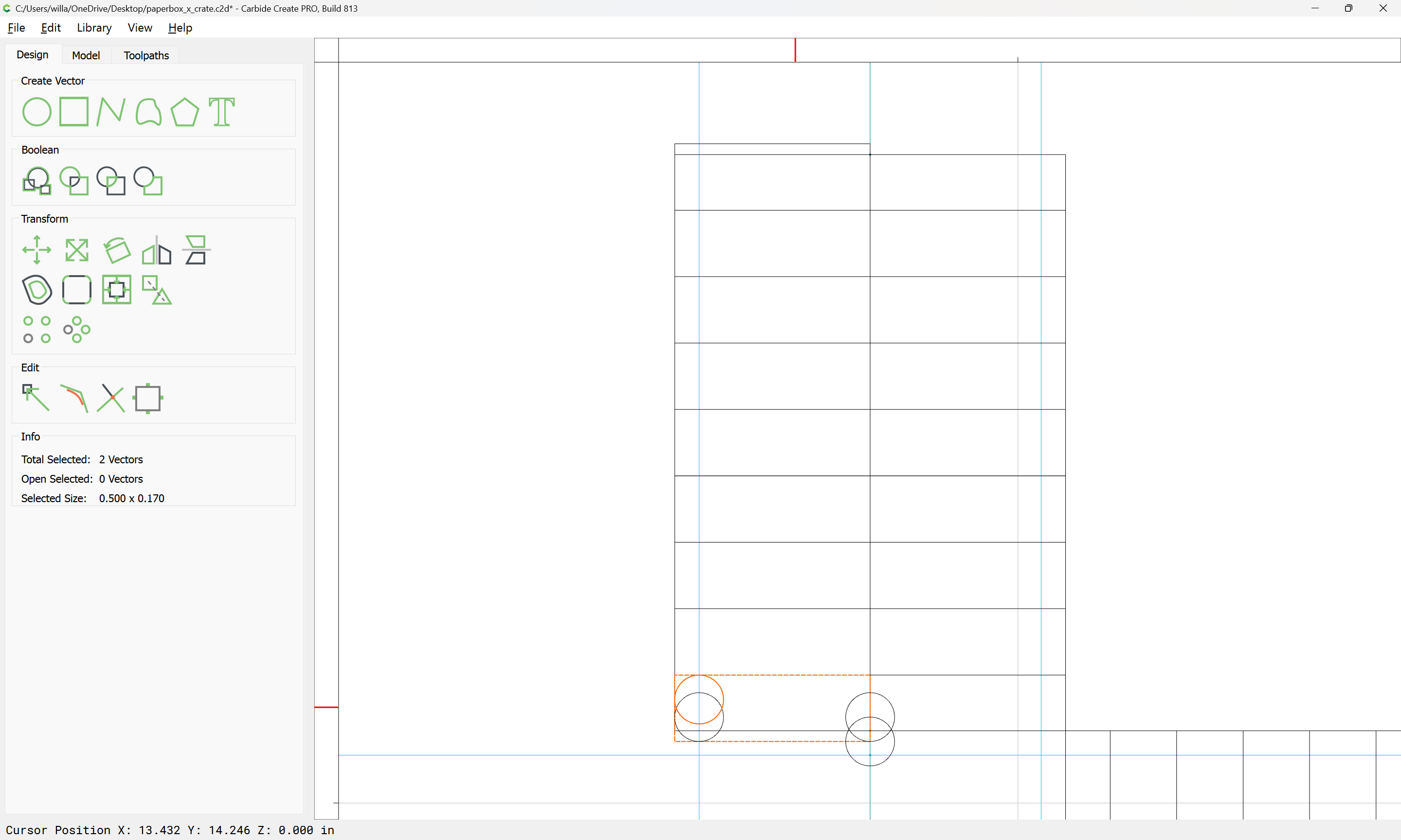
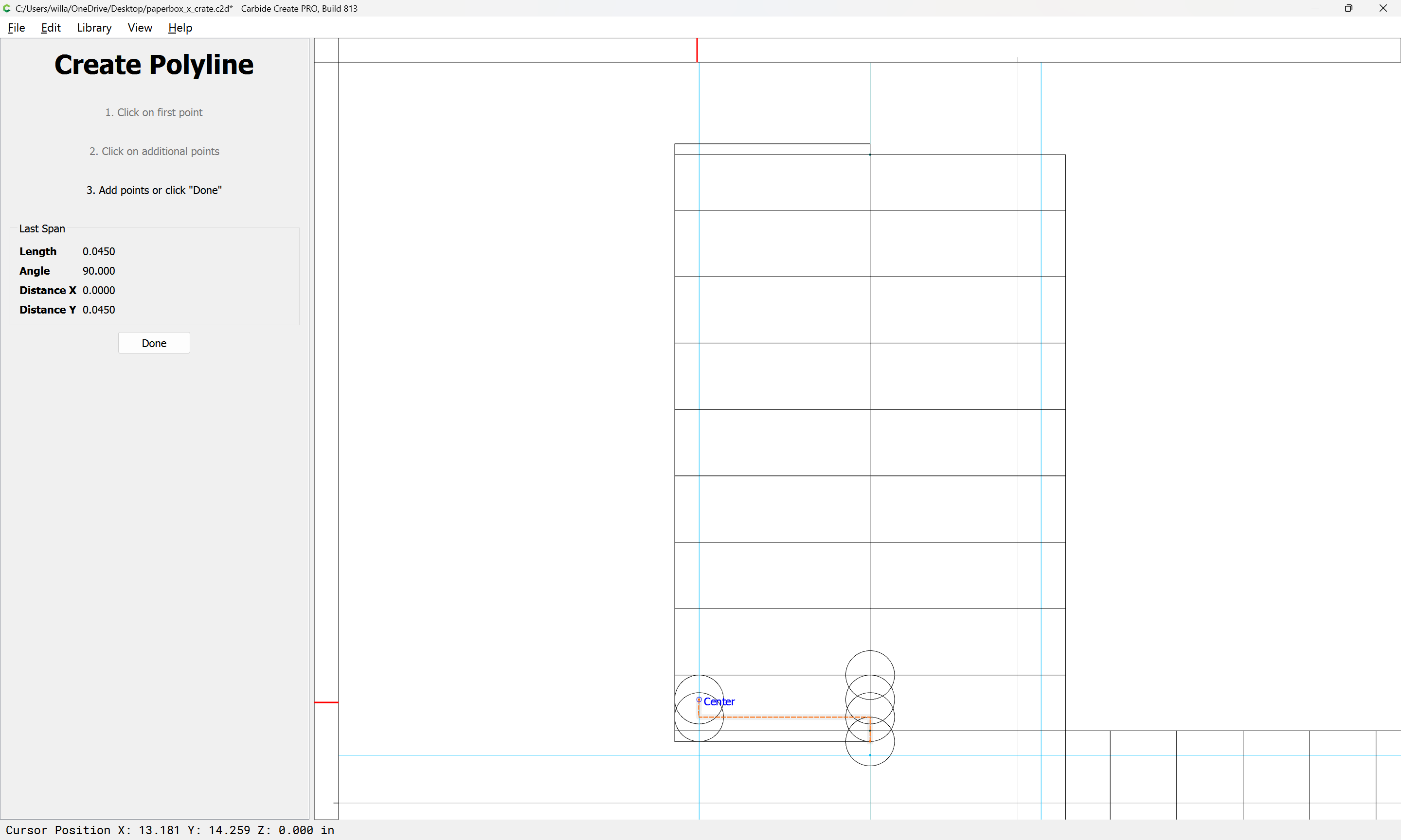
and duplicates it as necessary:
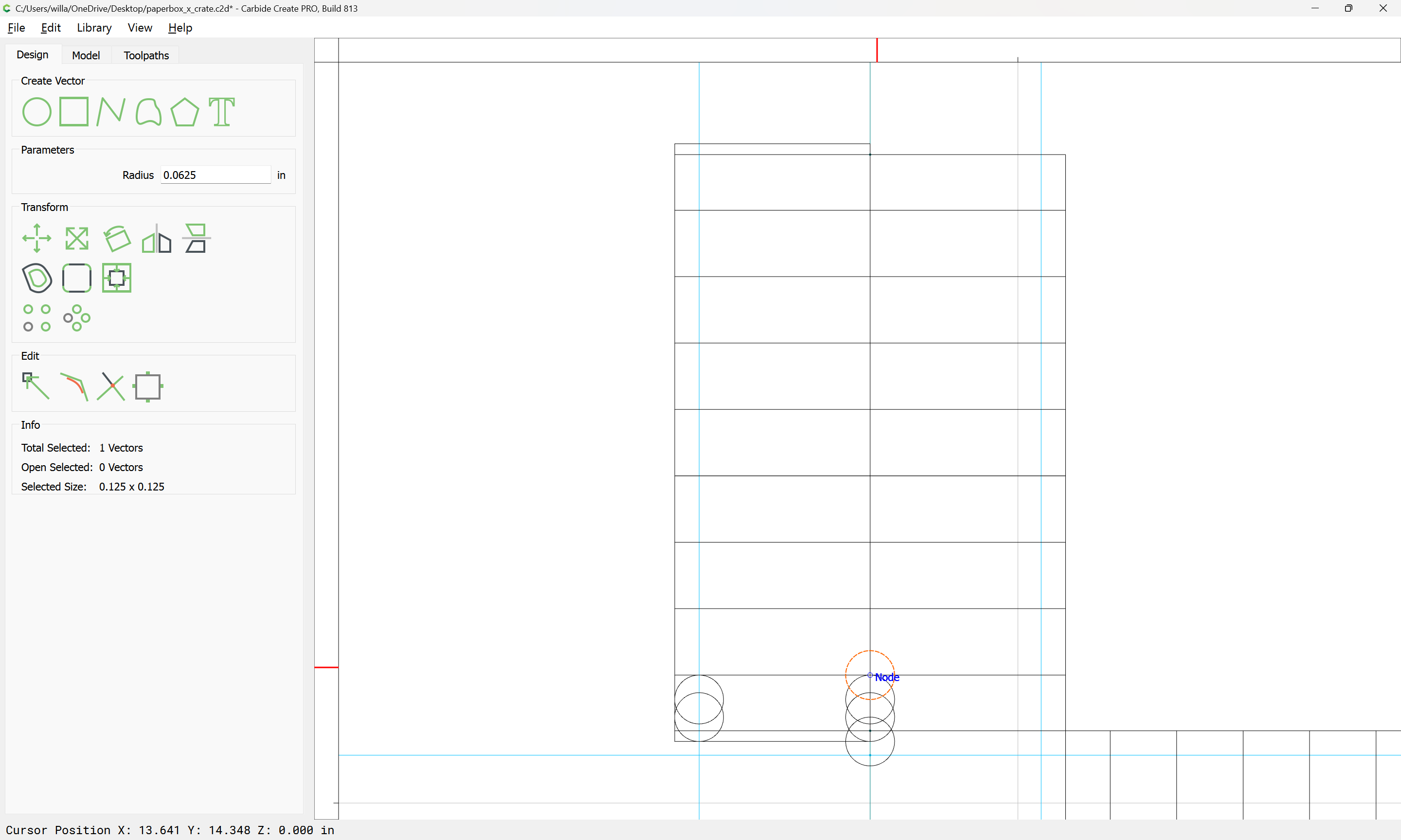
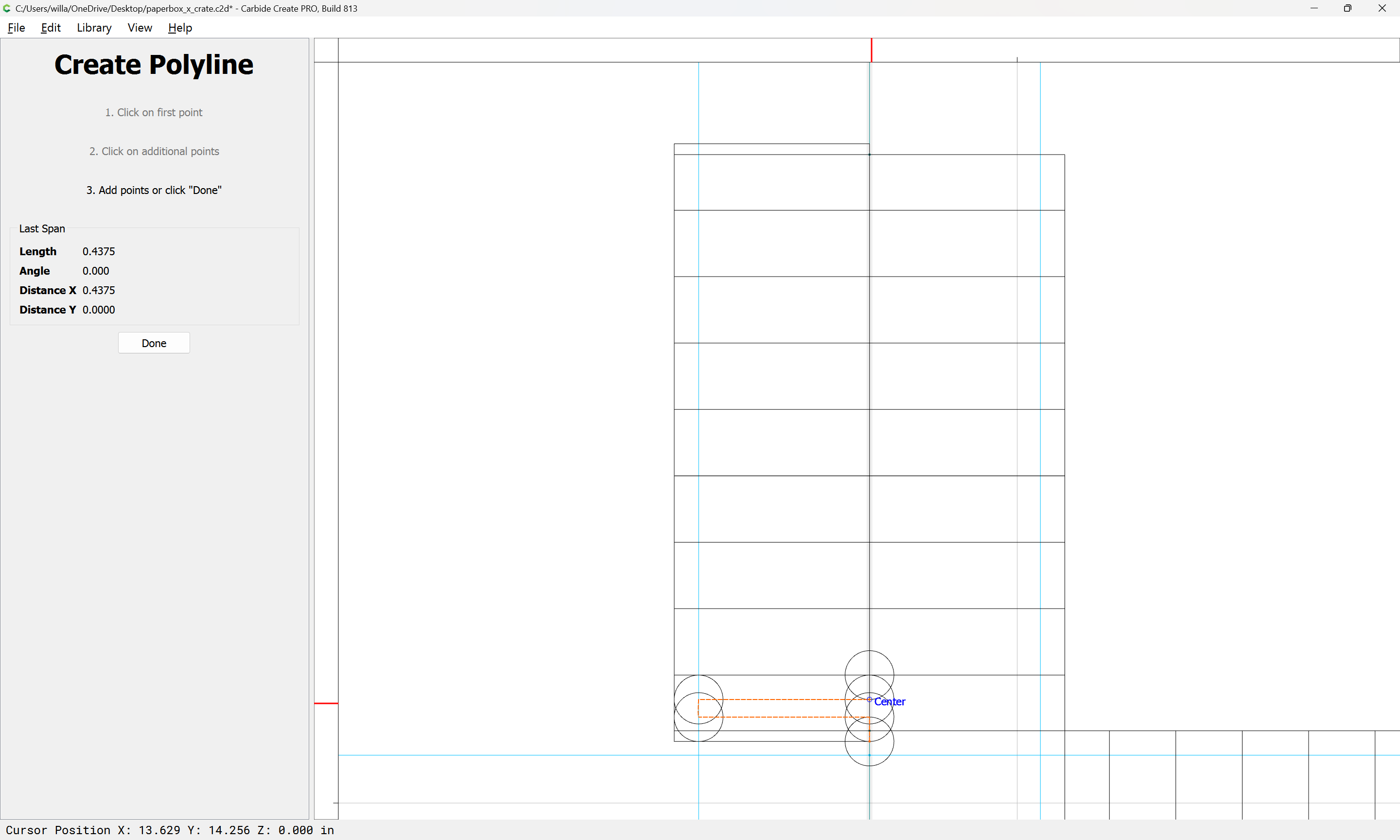
Align Vectors makes doing this quick and precise.
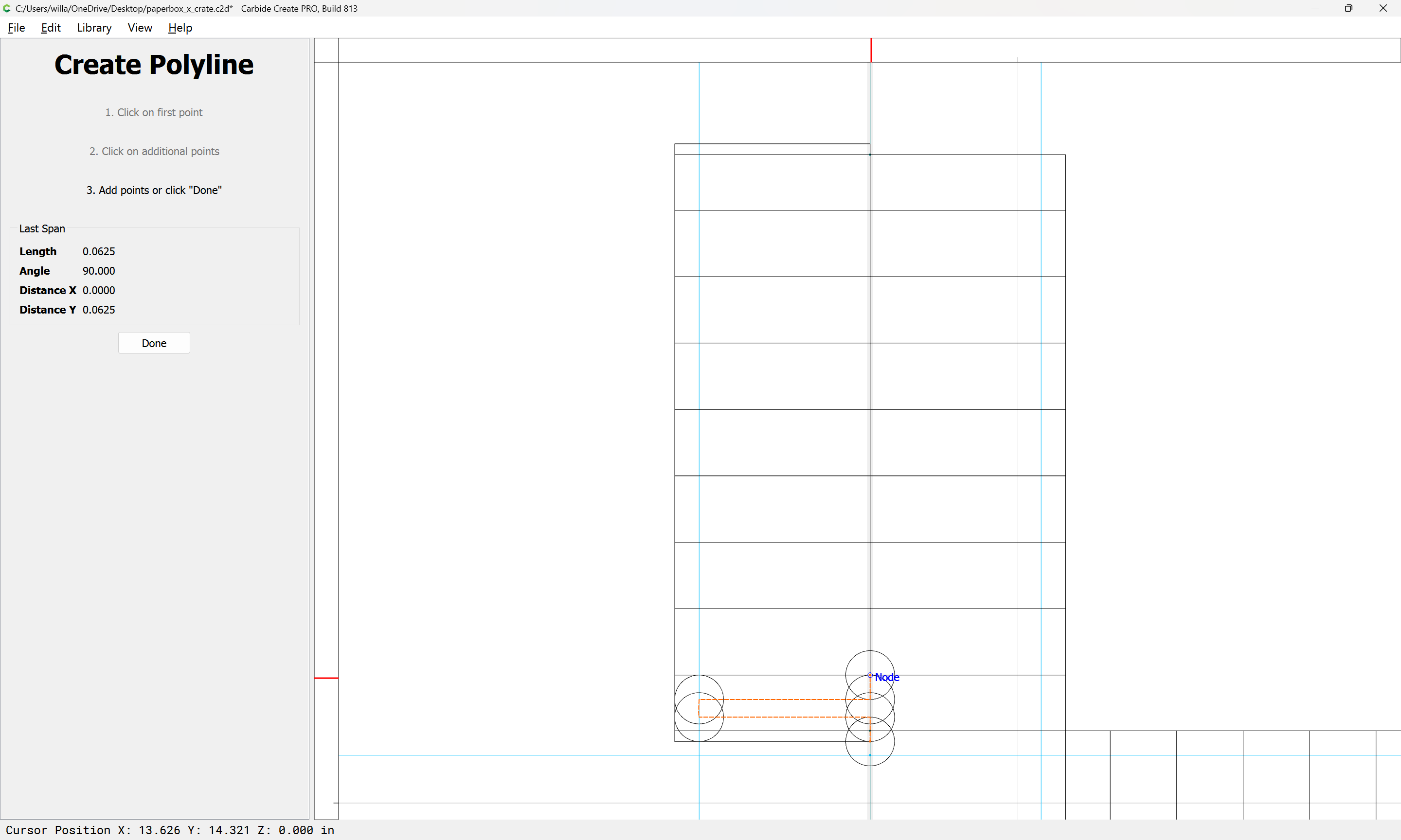
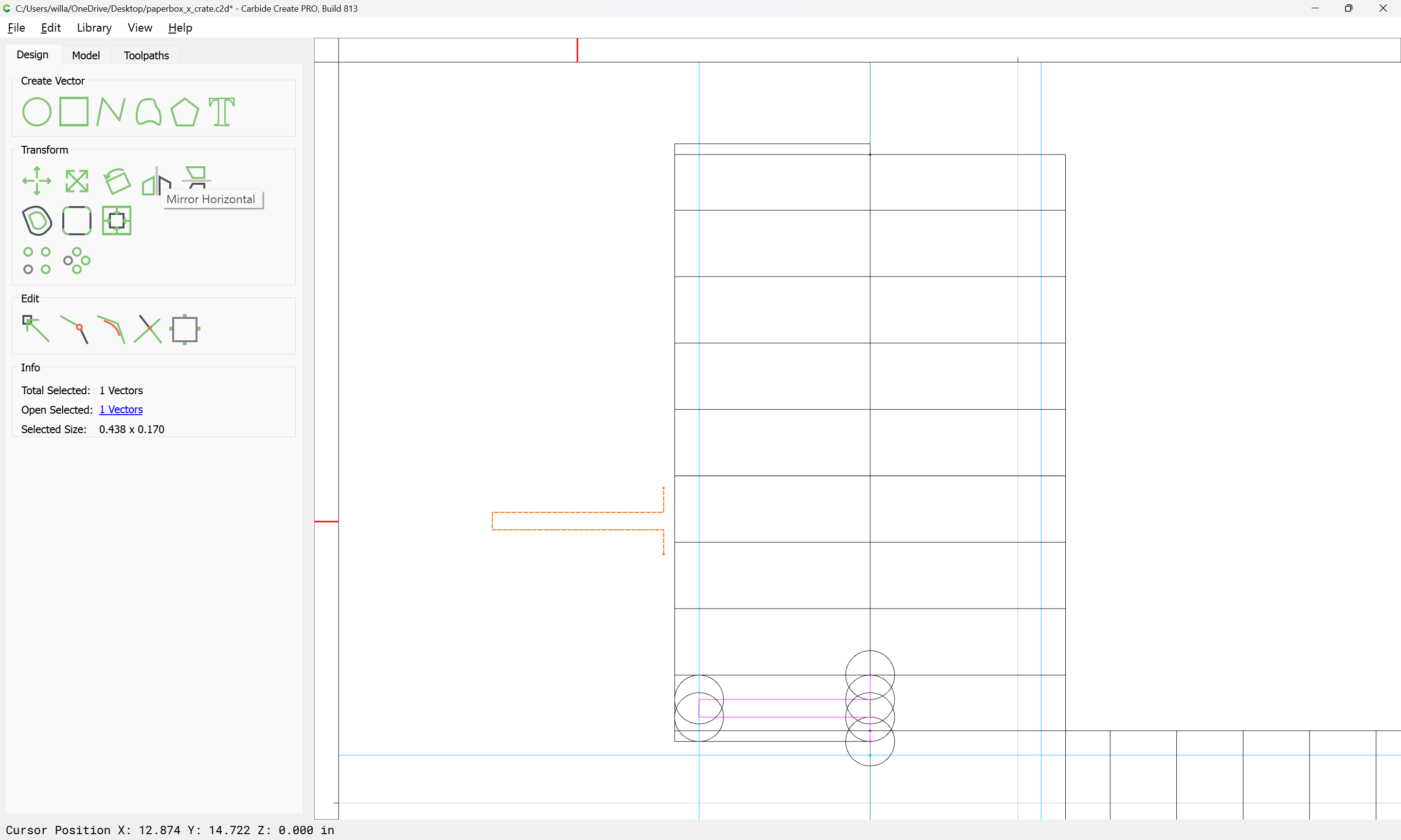
Then it is simply a matter of connecting the centers:
Done
Duplicate
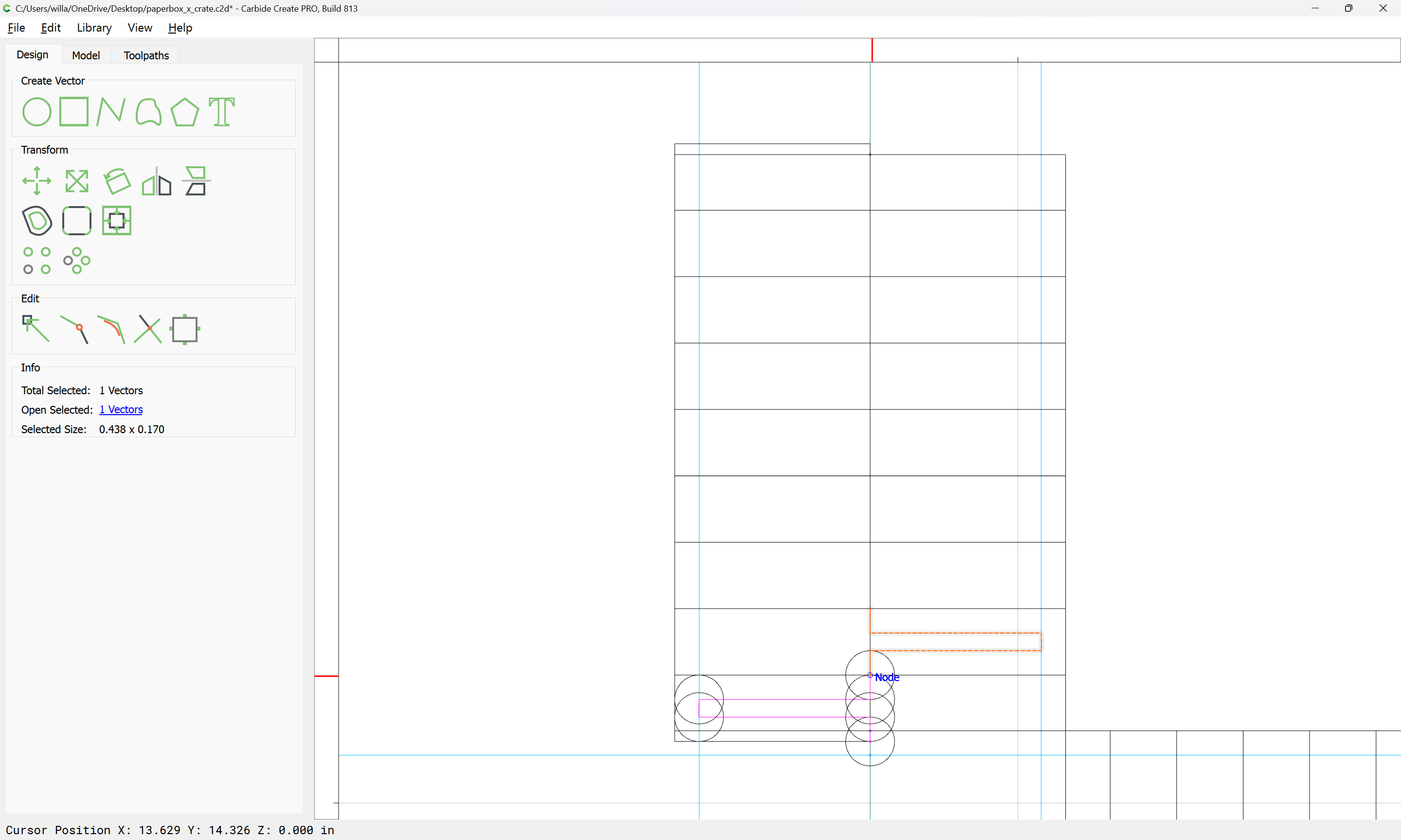
and Mirror Horizontal:
and drag into position:
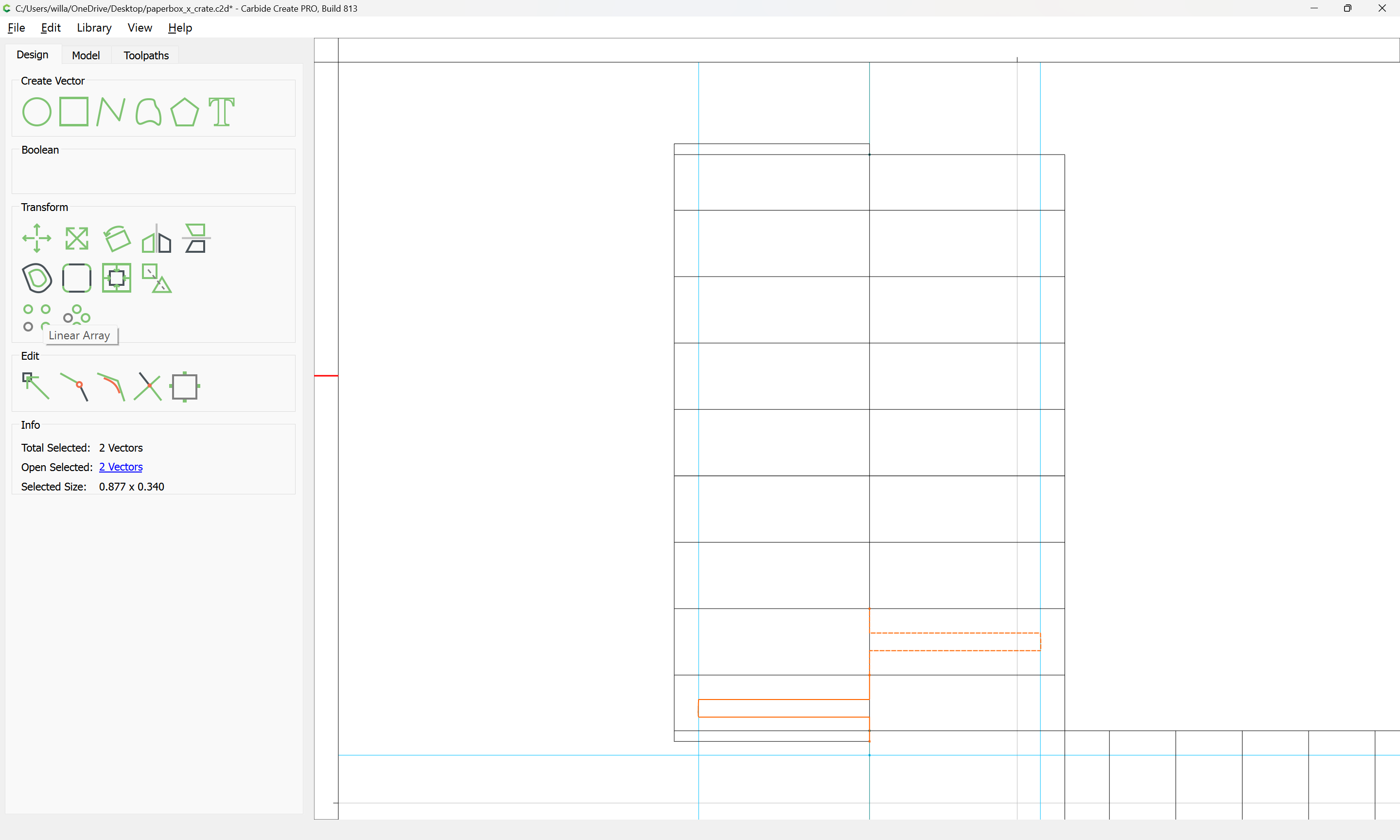
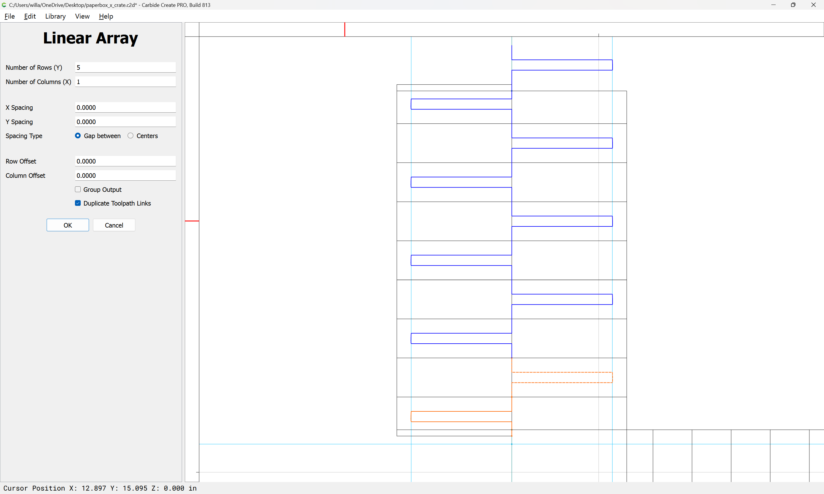
Then clean up, and use the Linear Array tool:
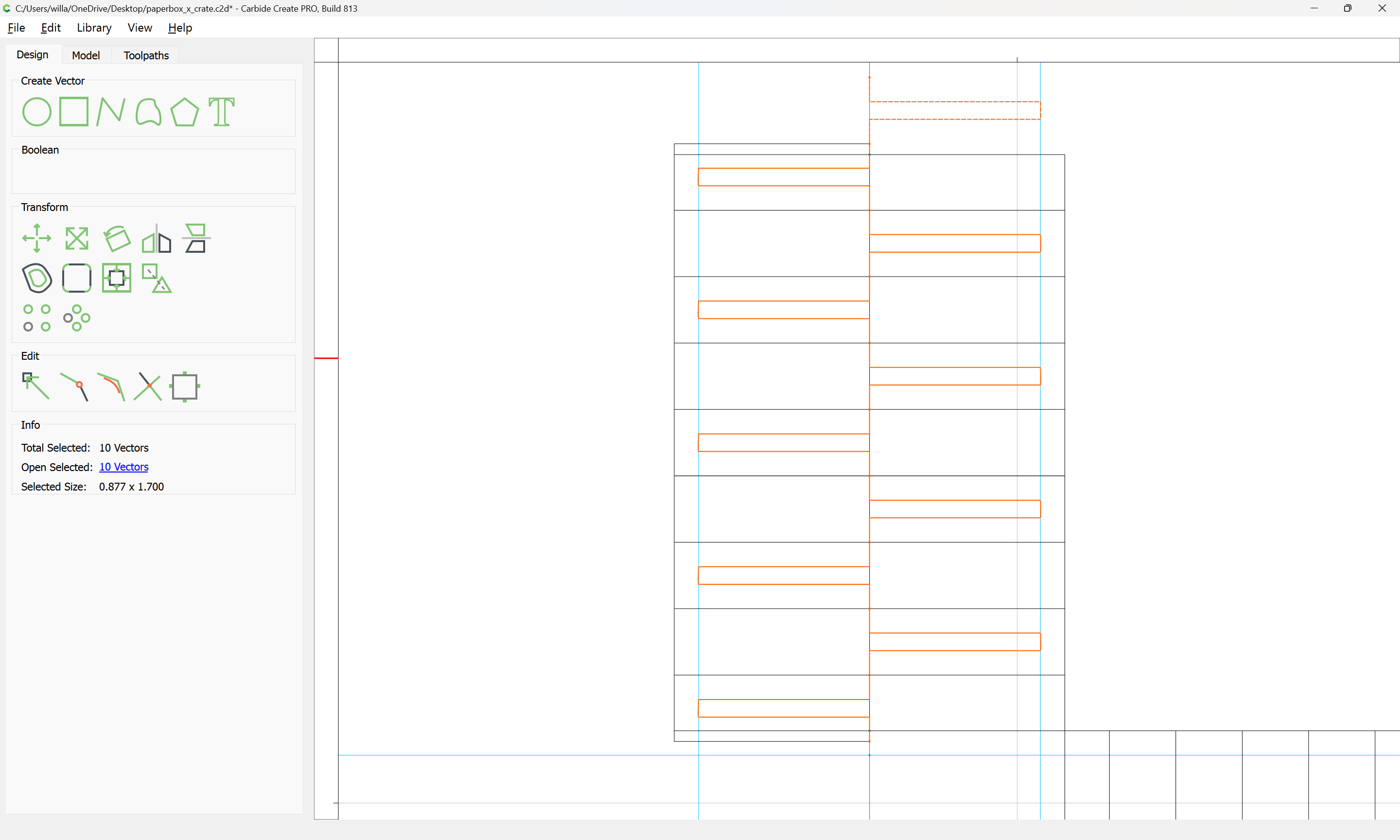
To duplicate as needed:
OK
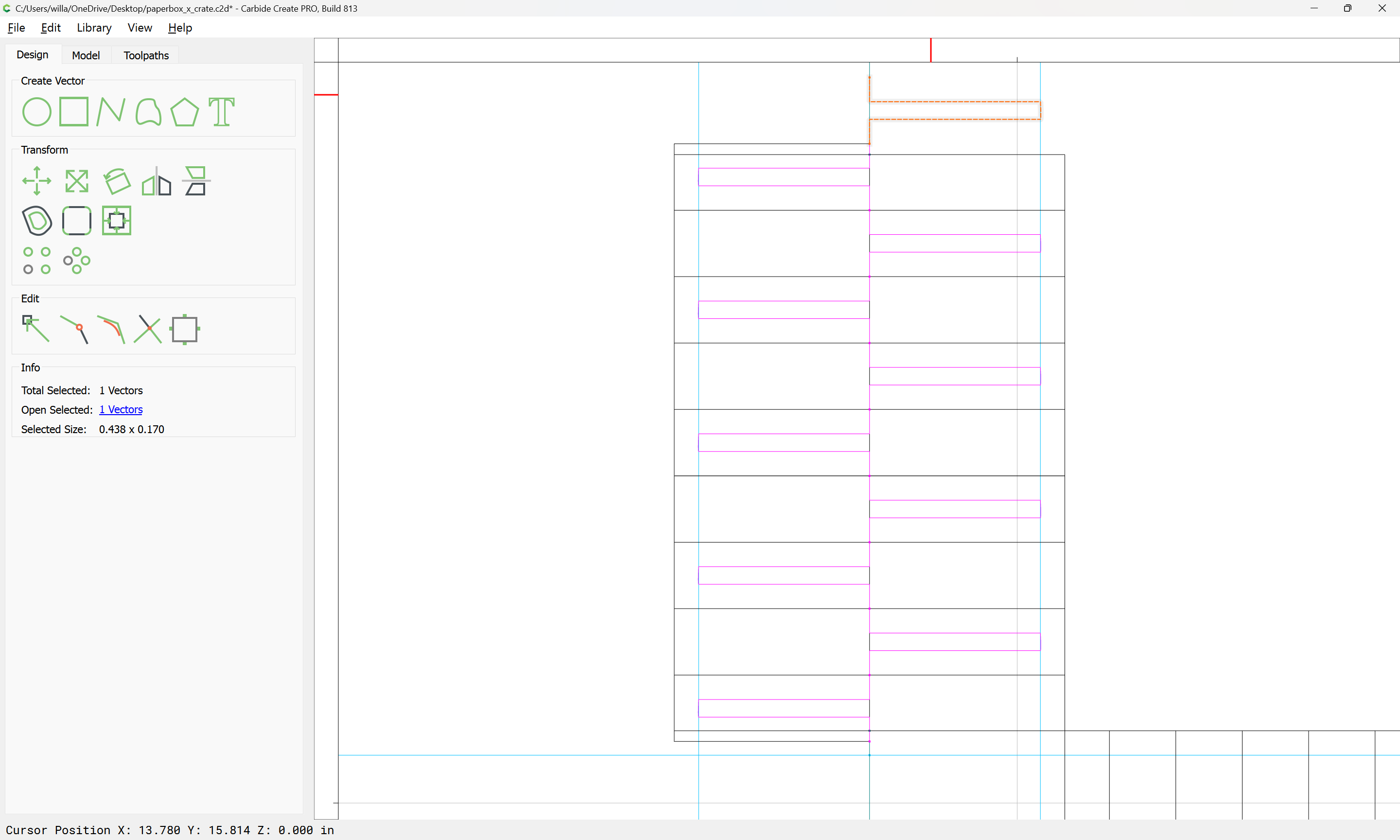
Select and delete the extra part:
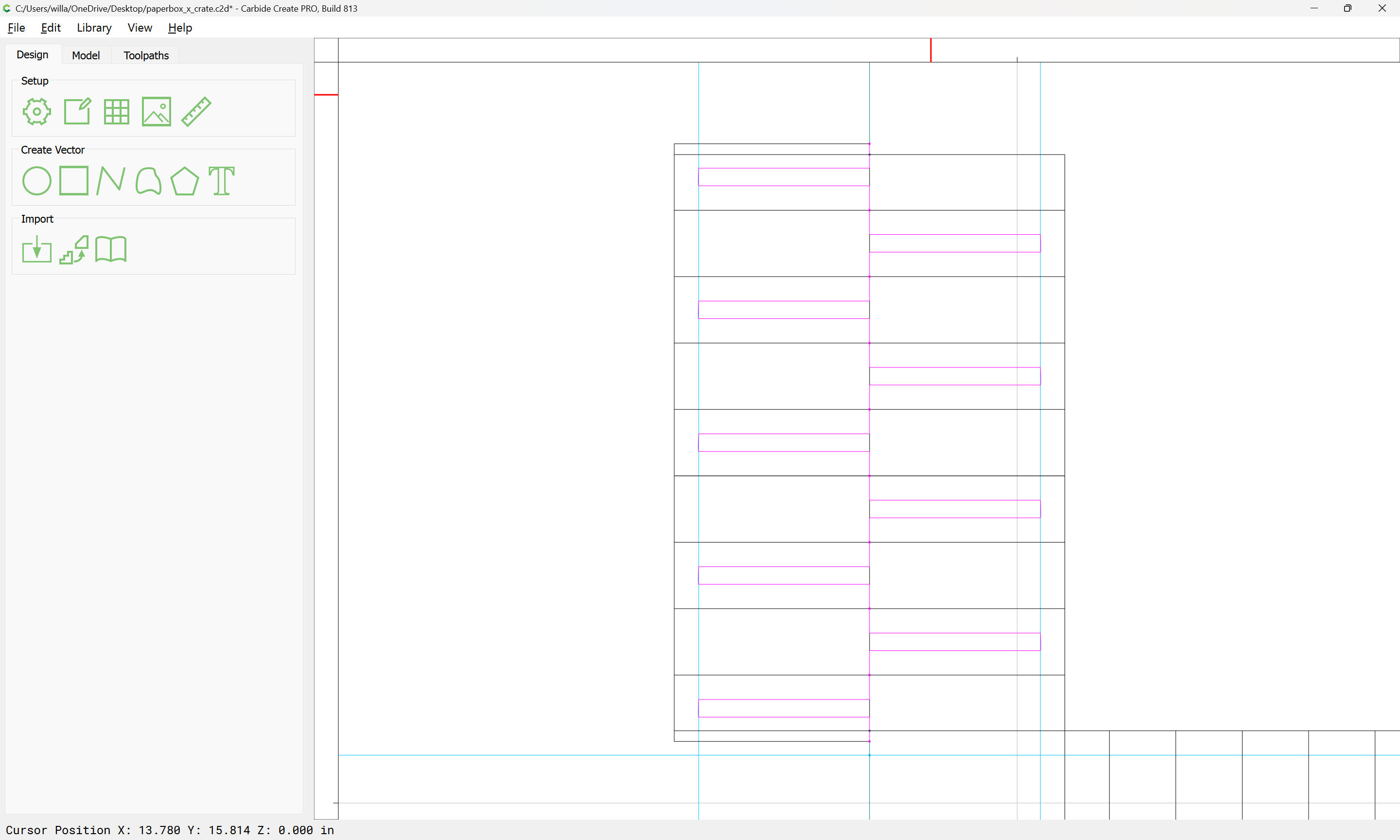
then create a new Layer:
and matching toolpath:
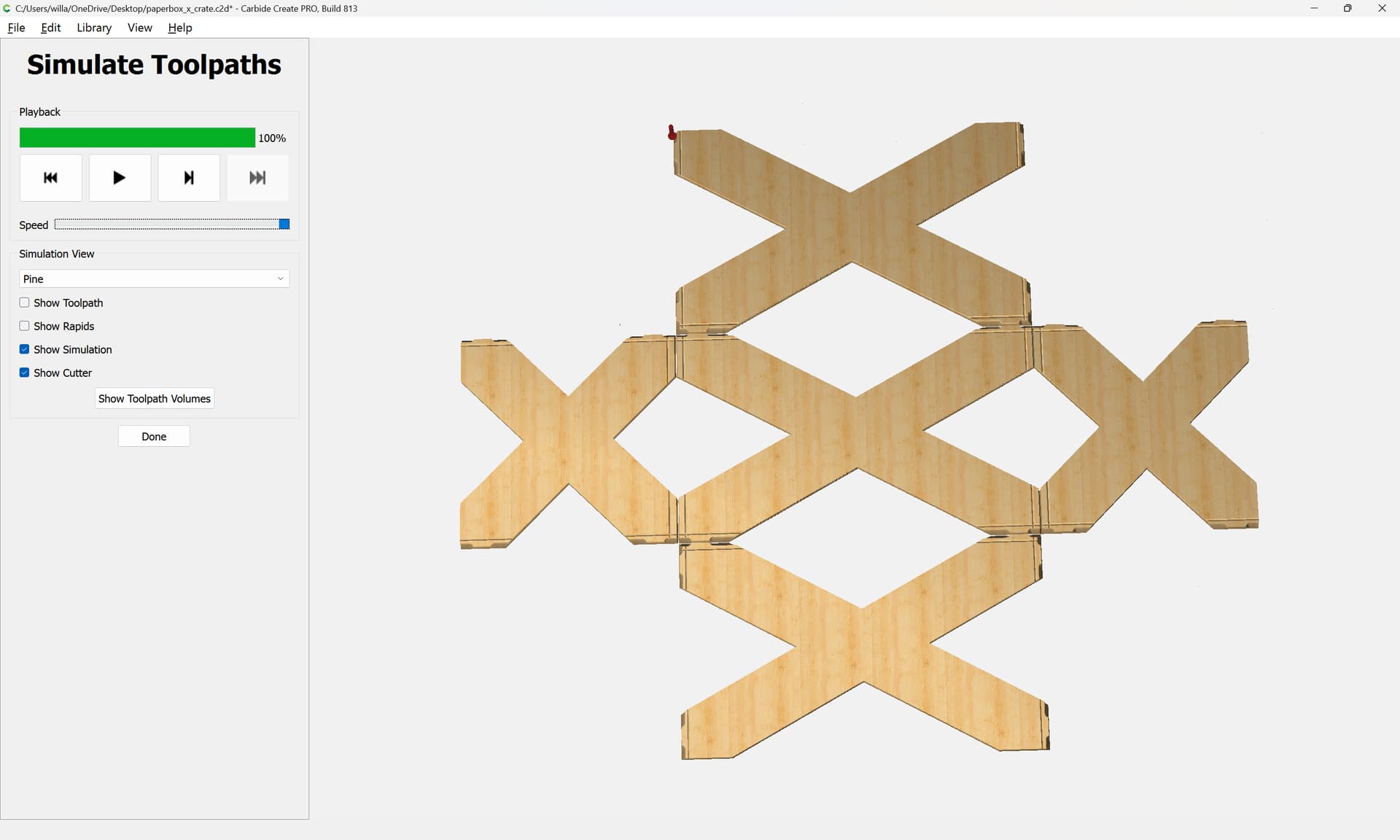
which allows one to get an idea of how things will fit together:
Duplicate and reposition as necessary.
WillAdams
February 2, 2025, 6:21pm
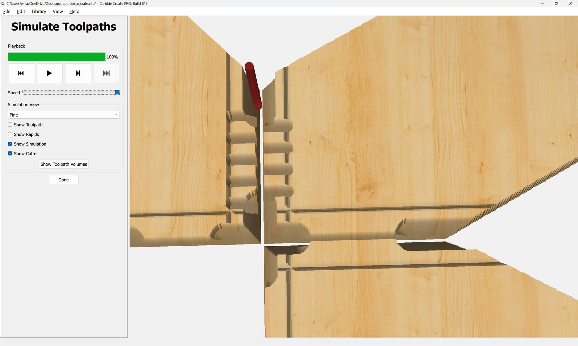
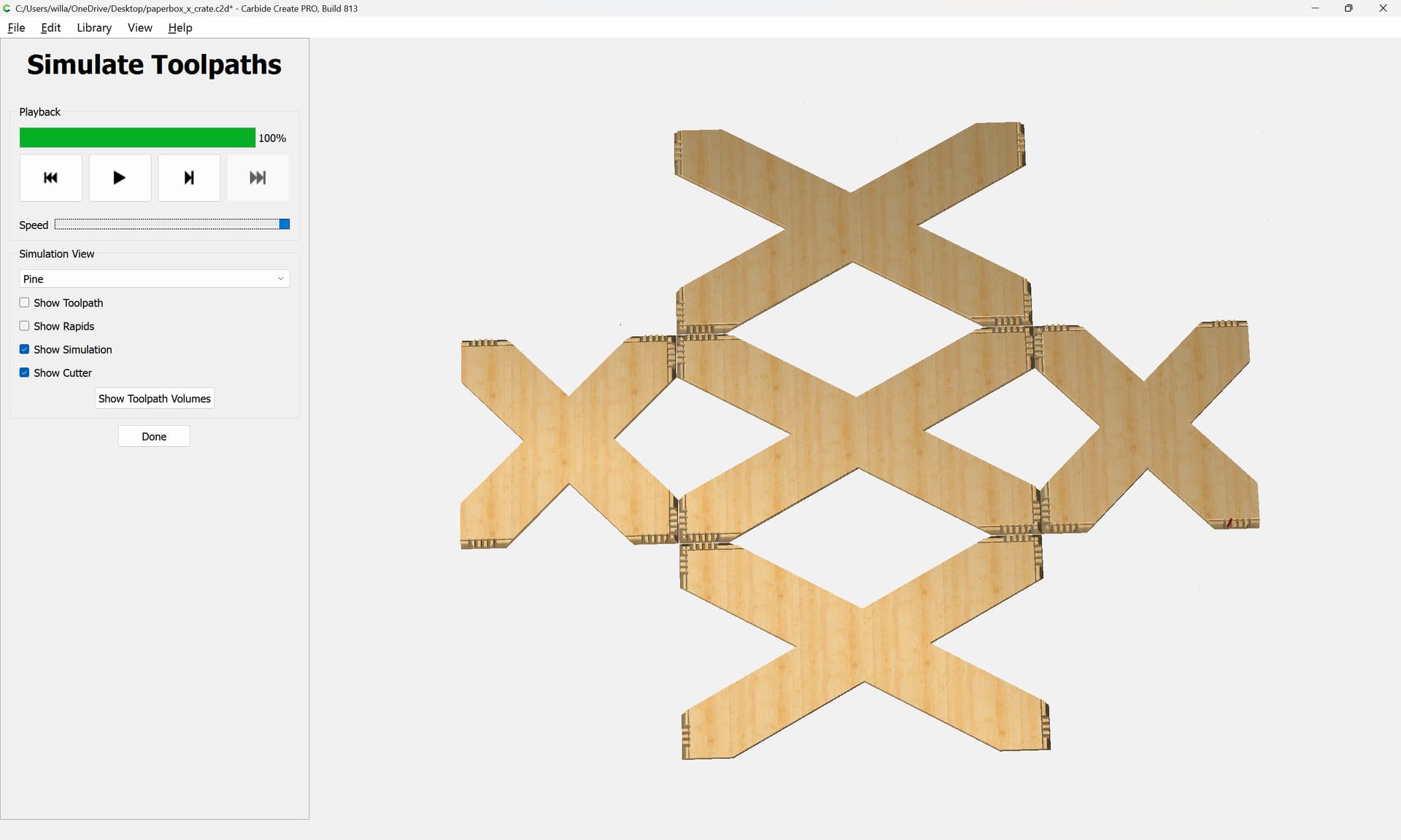
9
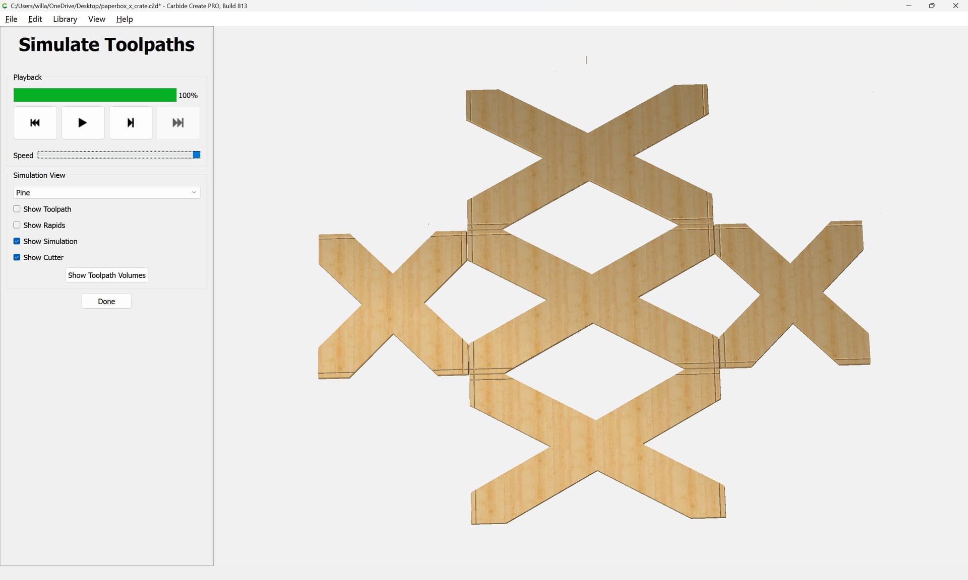
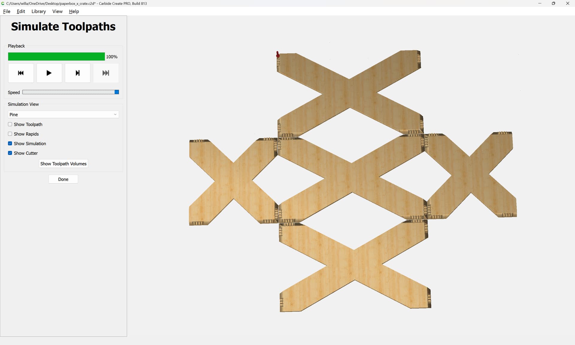
This then previews as:
which makes clear that we failed to finish drawing up the profile of the cut…
WillAdams
February 2, 2025, 7:04pm
10
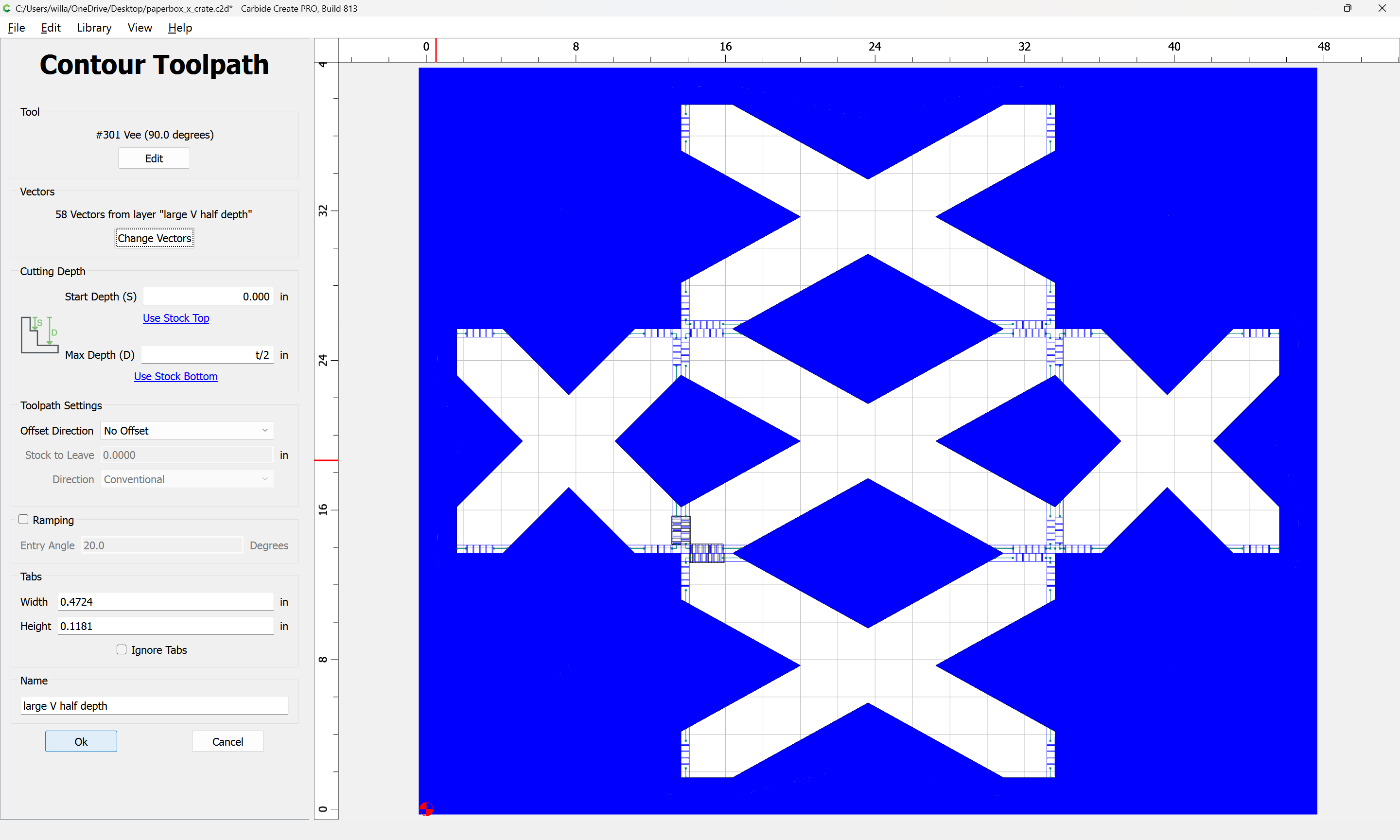
This of course reveals:
so we either want to use a larger V tool than a #301 , or, we need to add a toolpath.
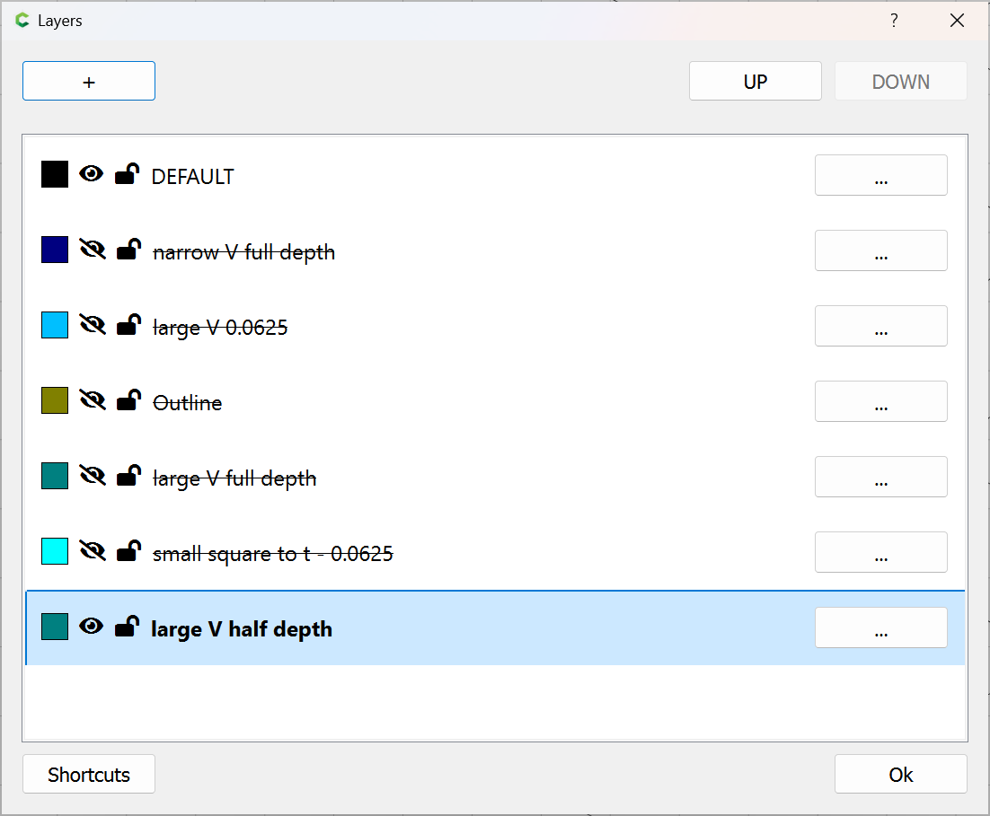
A quick duplication and positioning shows that we want things at the half-way mark:
so we create a new layer, duplicate the elements, hide the other lines:
and then reposition by 0.25" in the correct direction for each:
Note that some elements will need to be duplicated:
and re-positioned:
Done
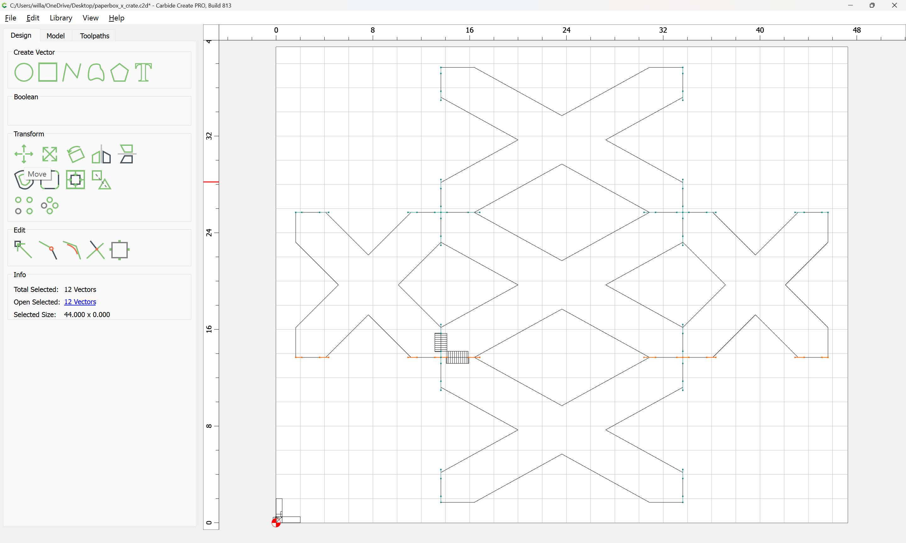
Repeat until we arrive at:
where we see that some elements cross each other, leading to redundant cuts:
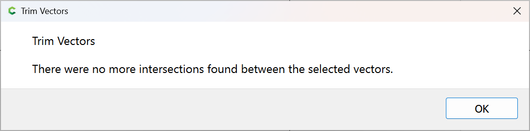
Select and use Trim Vectors to tidy things up:
OK
OK
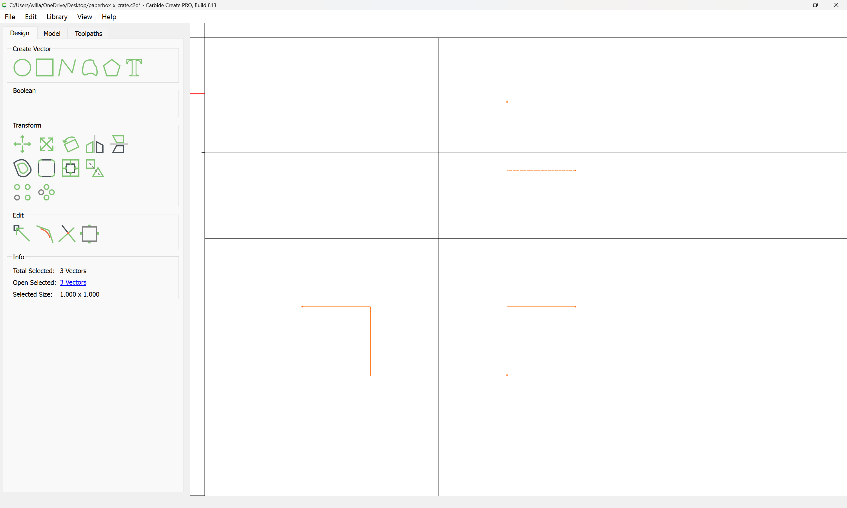
Use Join Vectors to connect:
and repeat everywhere else this happens.
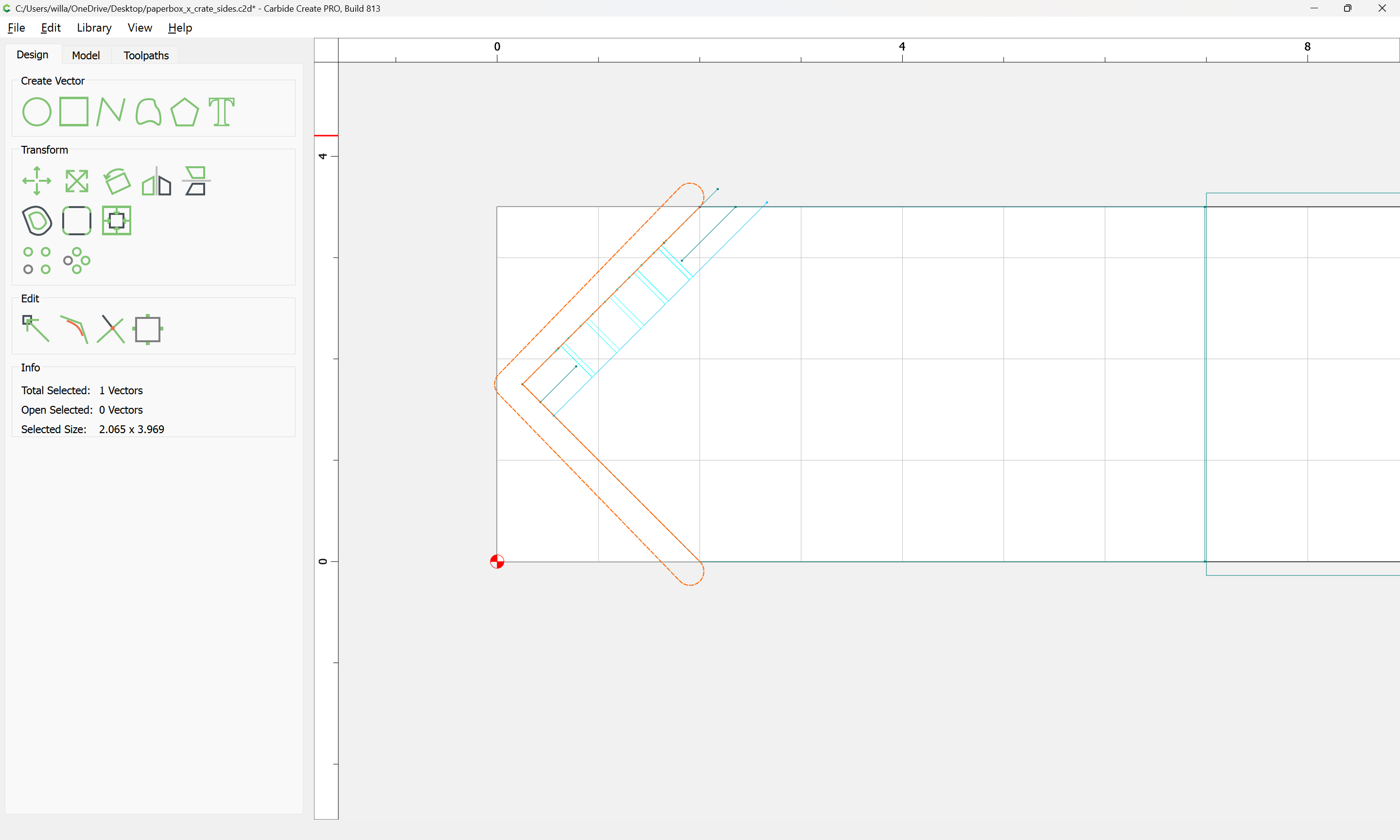
Then create a toolpath:
which just leaves the matter of the intersections, and dividing up (and where necessary duplicating) the toolpaths and geometries so that they may be cut out of suitable boards.
WillAdams
February 2, 2025, 11:47pm
11
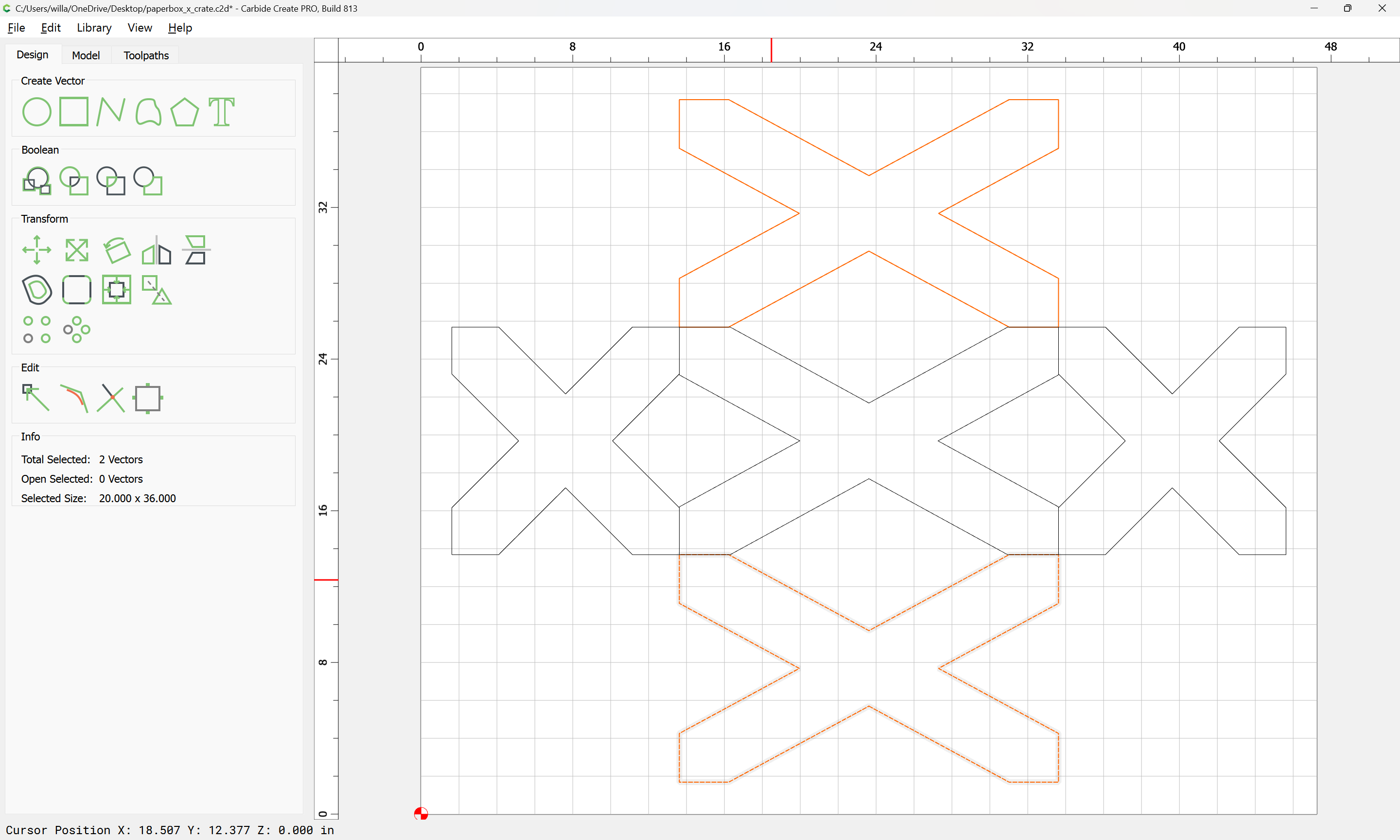
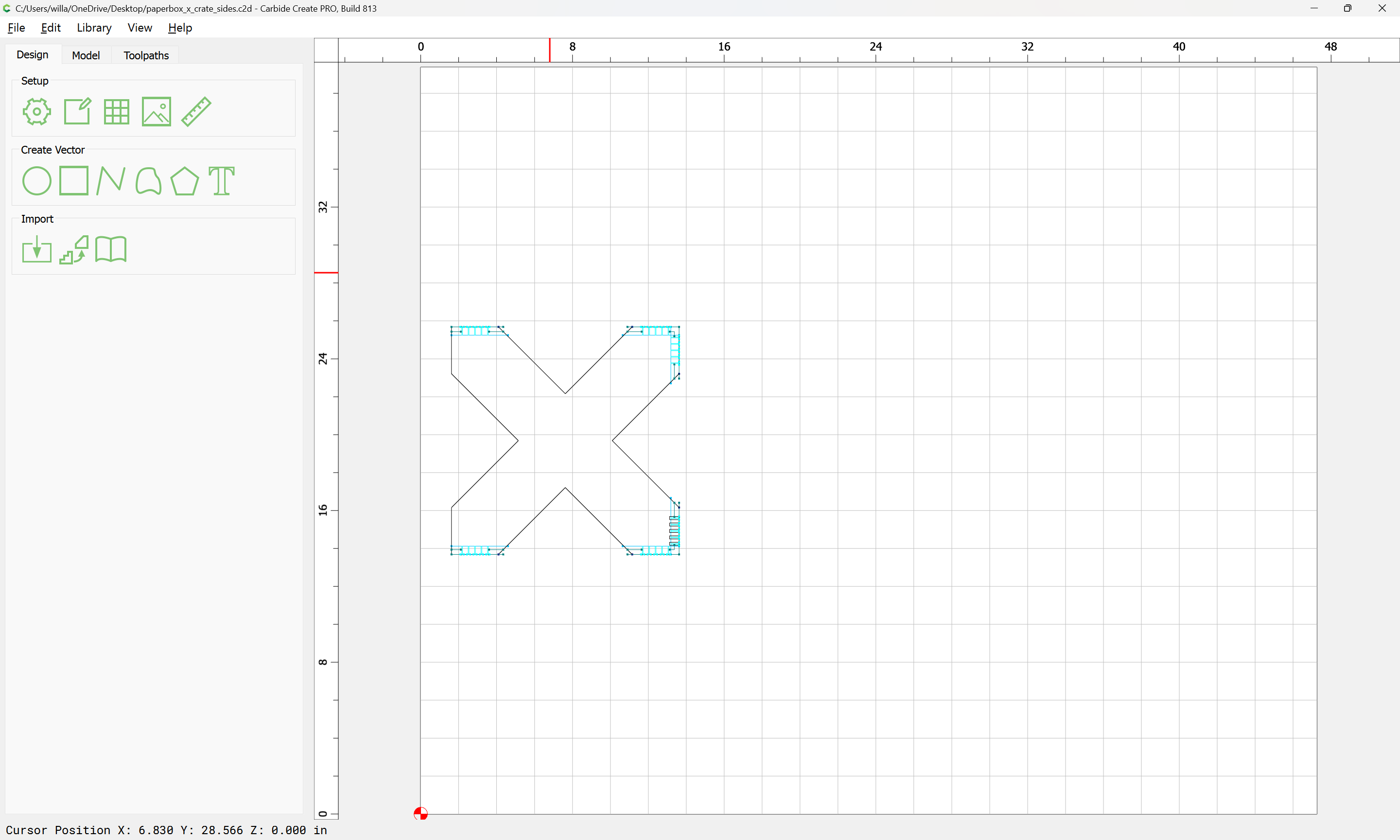
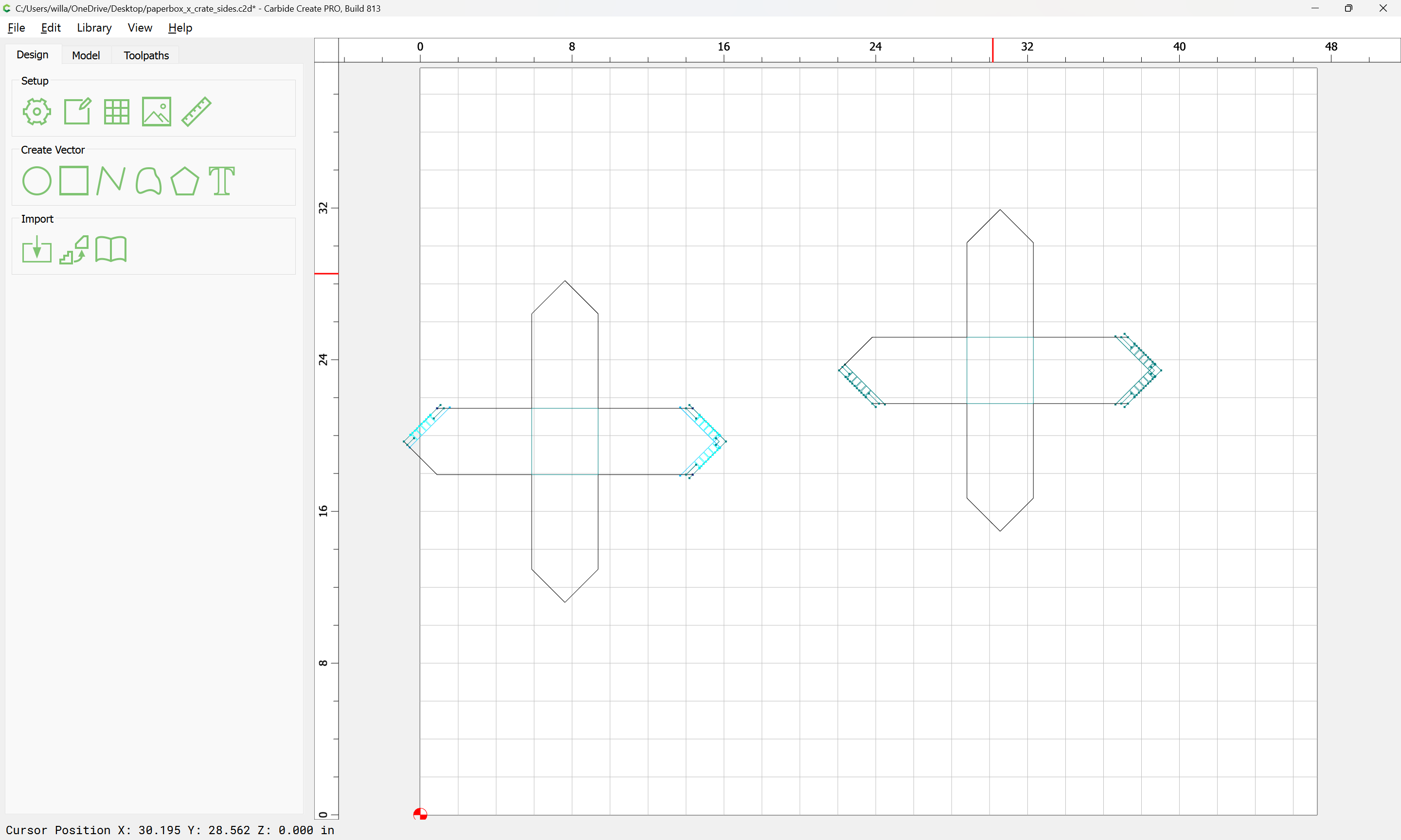
Open the file and save under a new name, make all the layers visible, and delete all other parts:
Duplicate:
Rotate one copy 45 degrees, the other -45 degrees:
Draw in a rectangle on each copy for the rabbet:
Delete the elements for the other board for each:
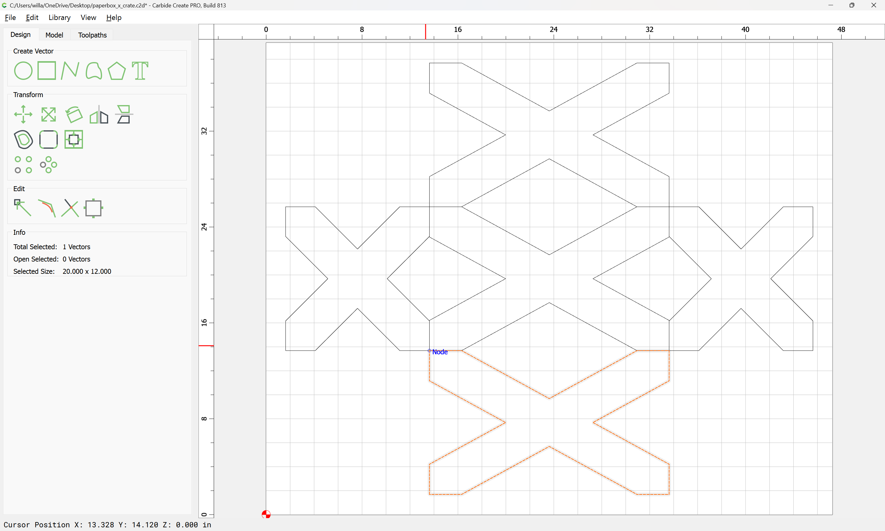
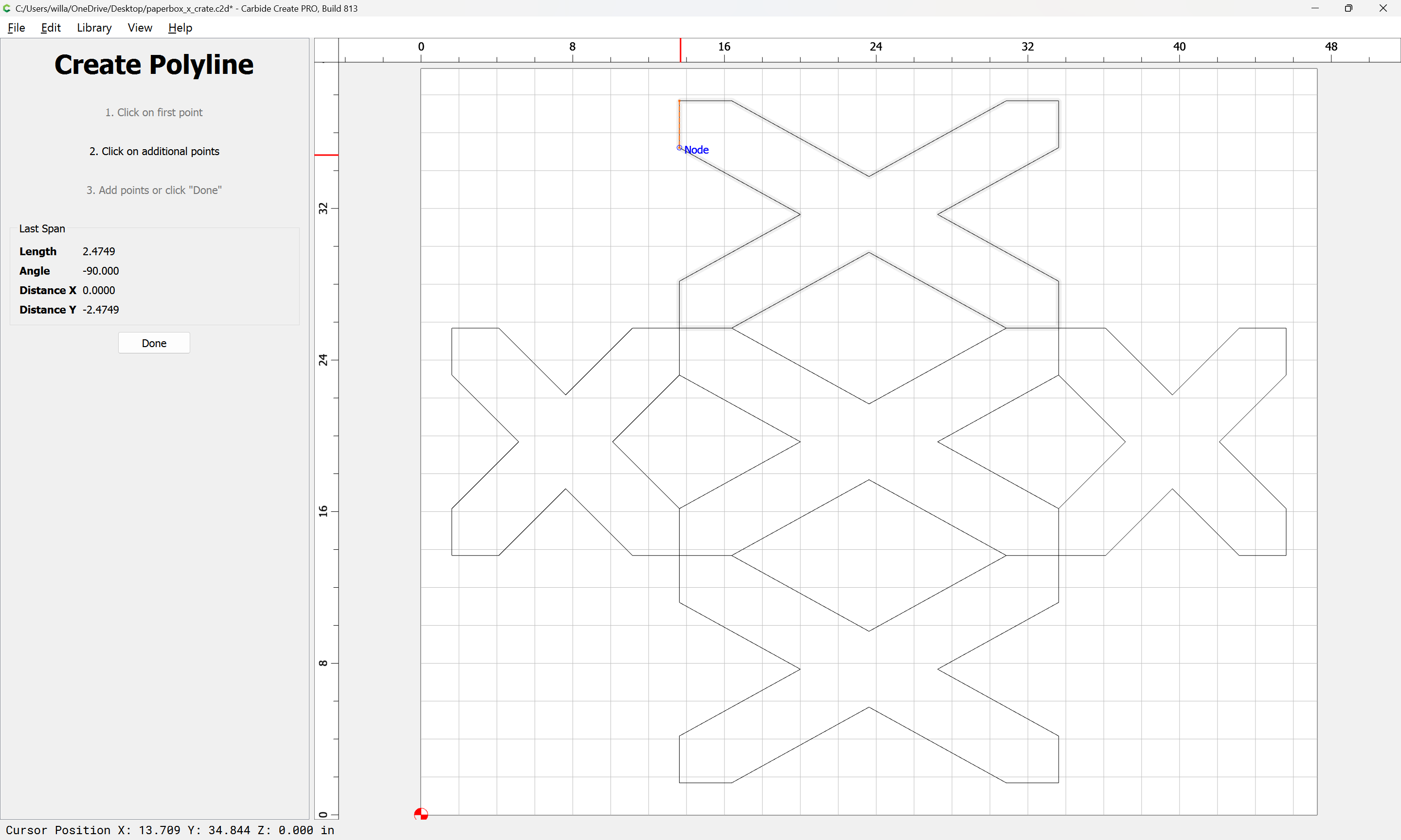
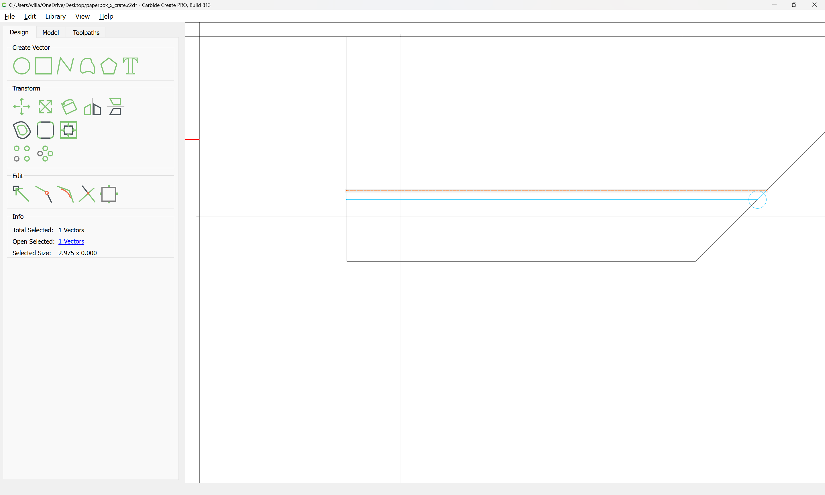
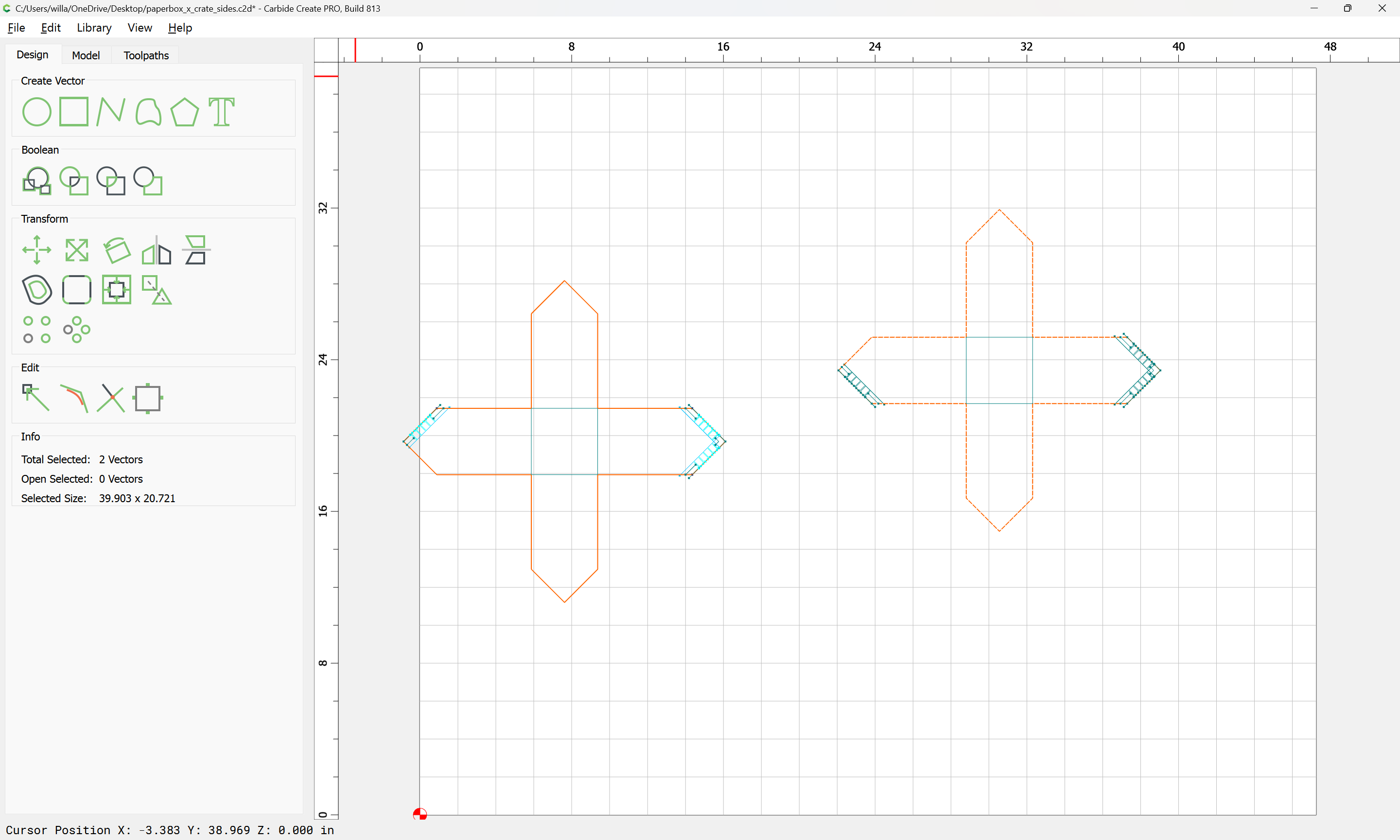
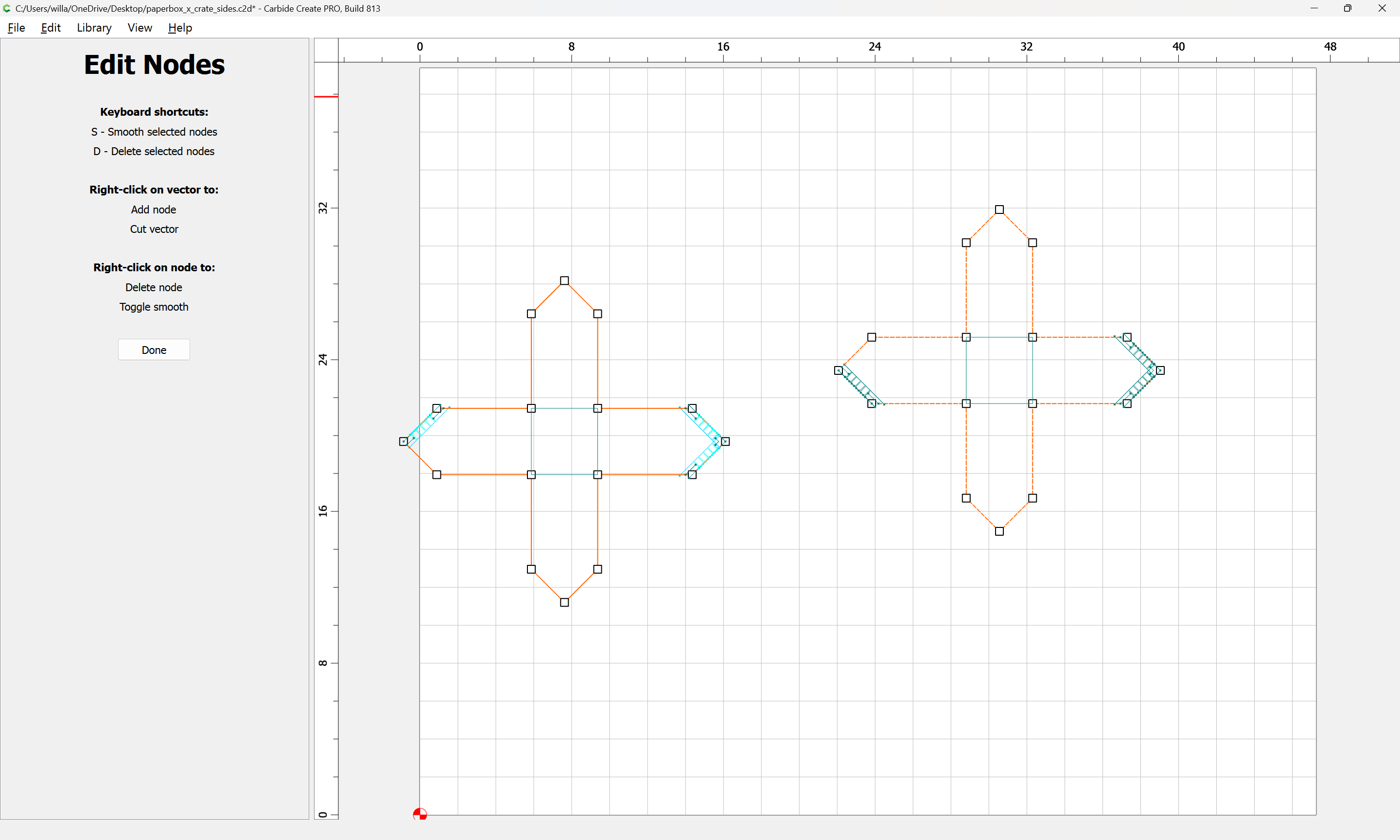
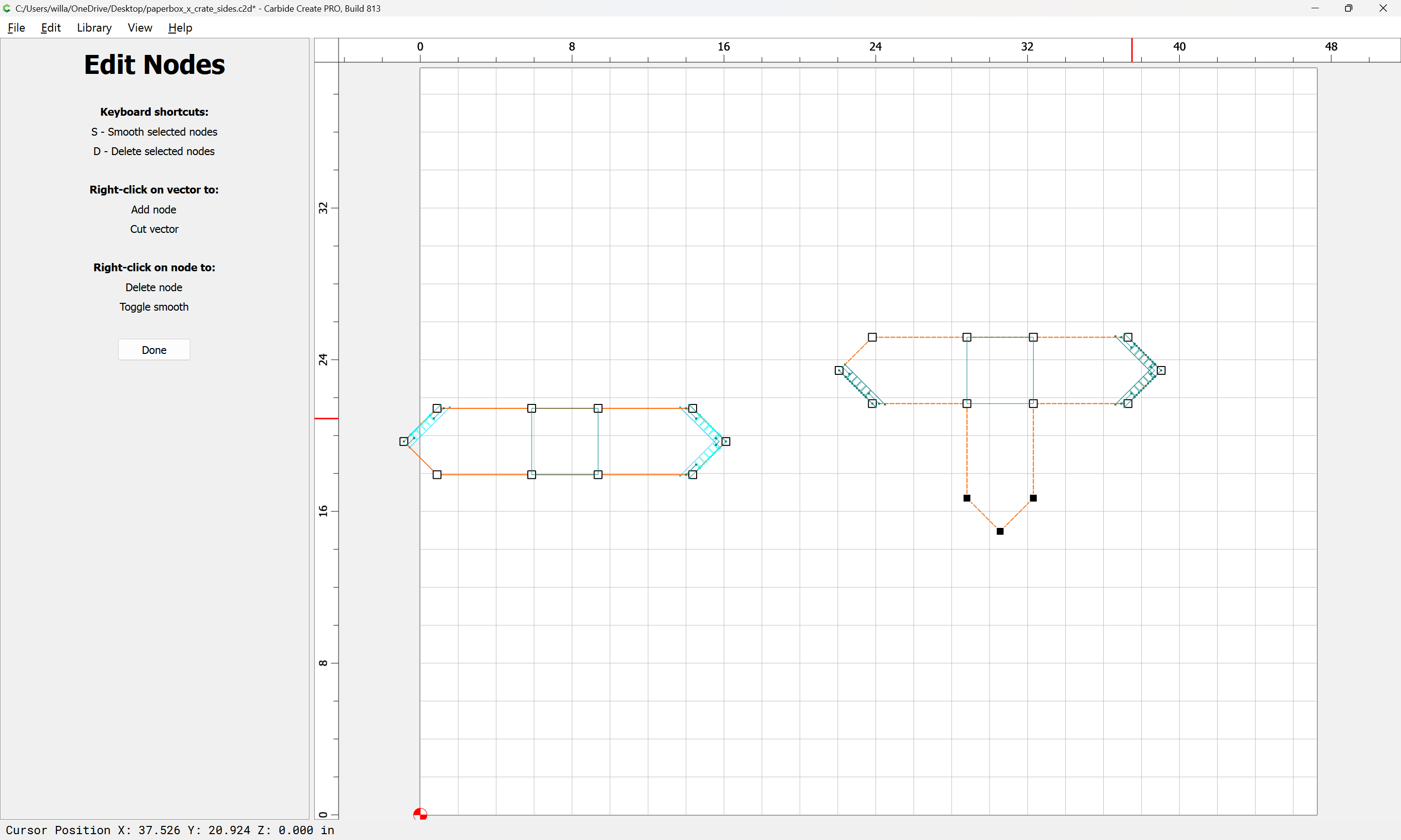
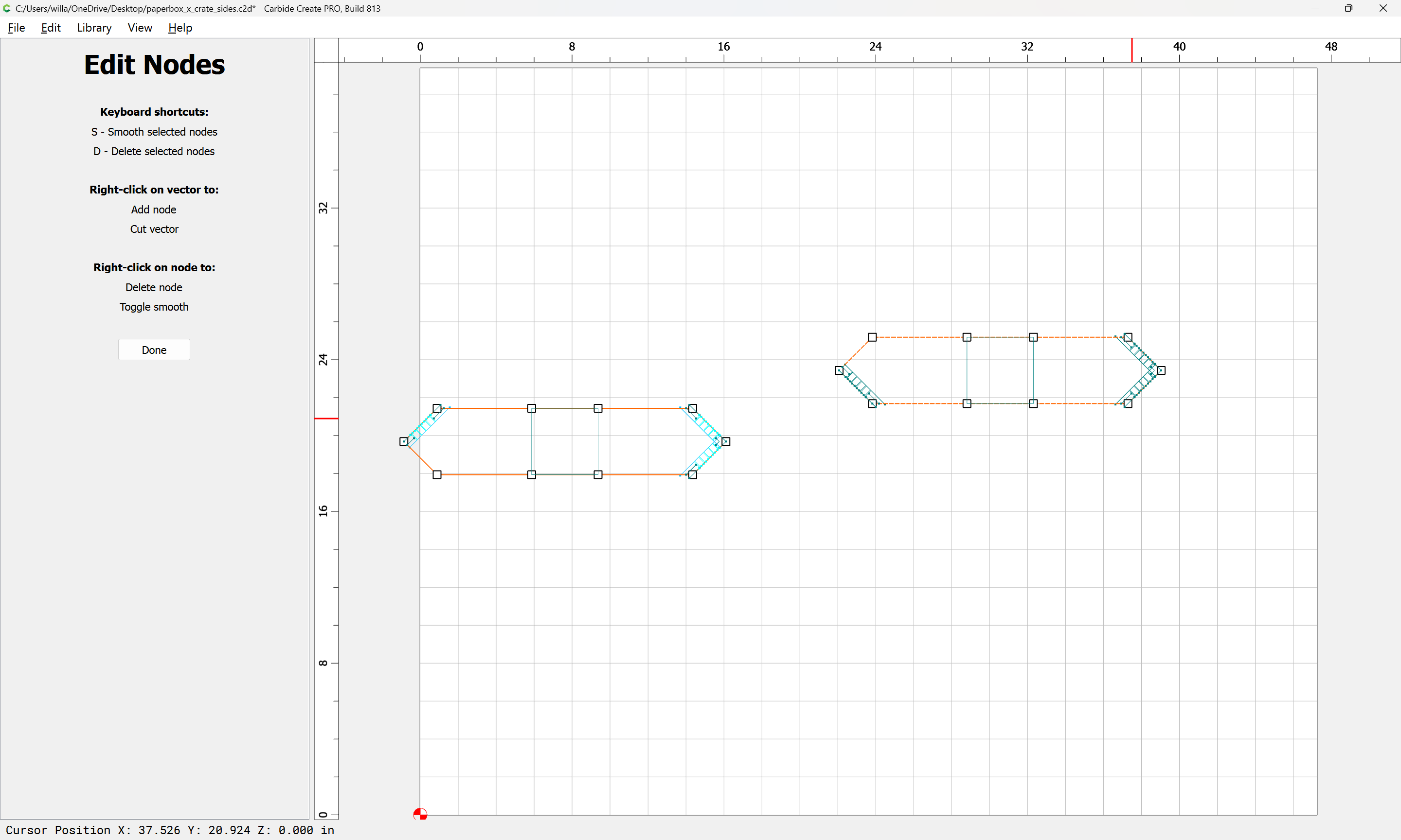
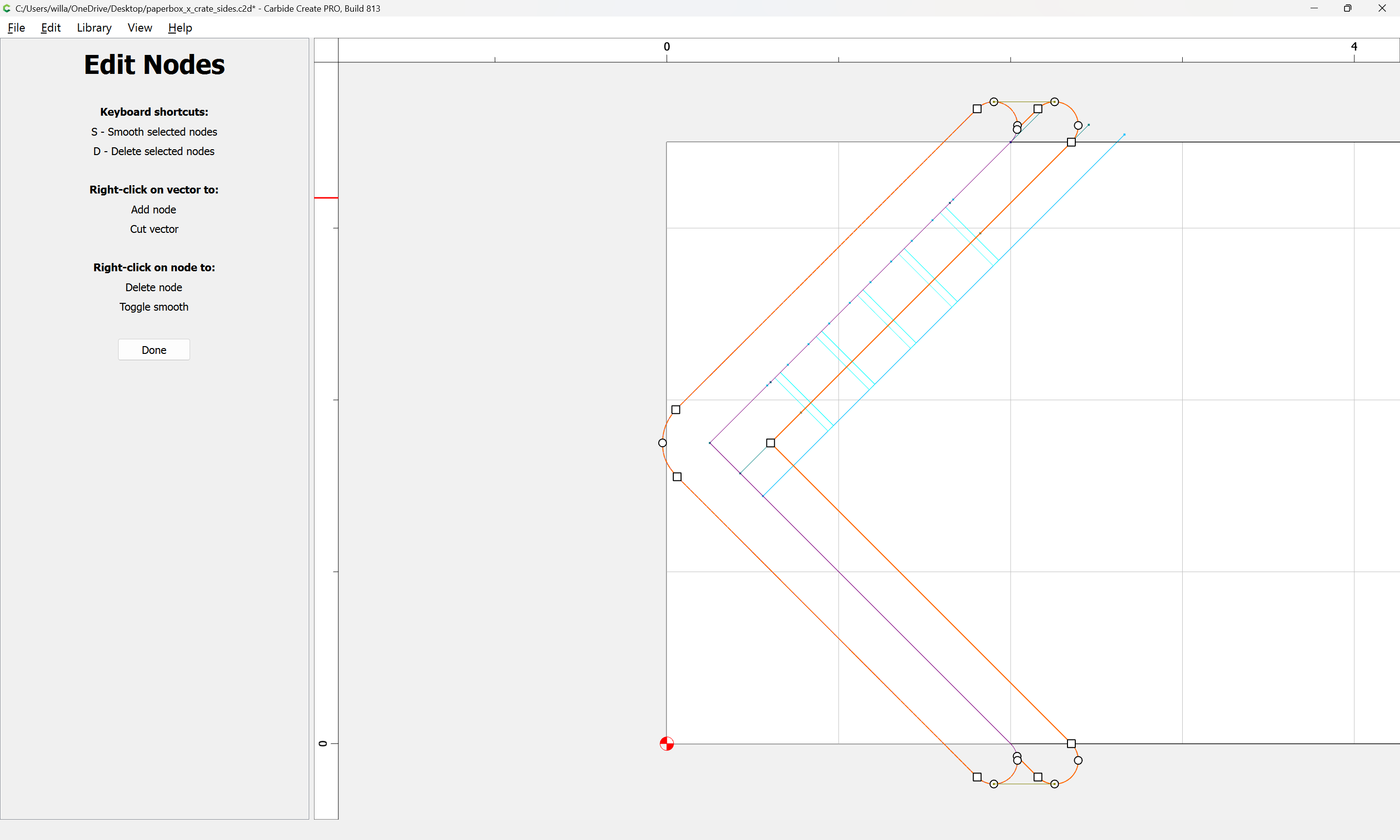
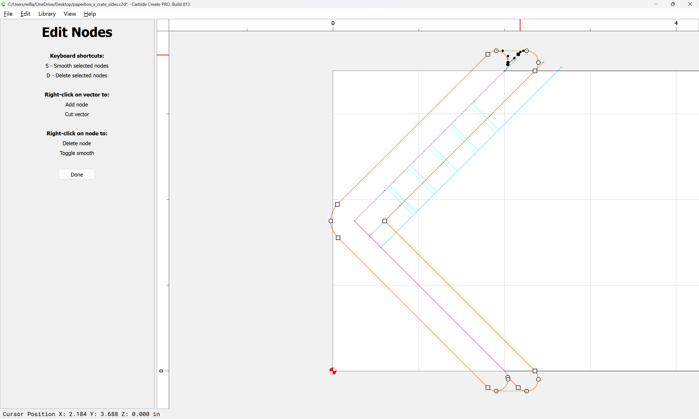
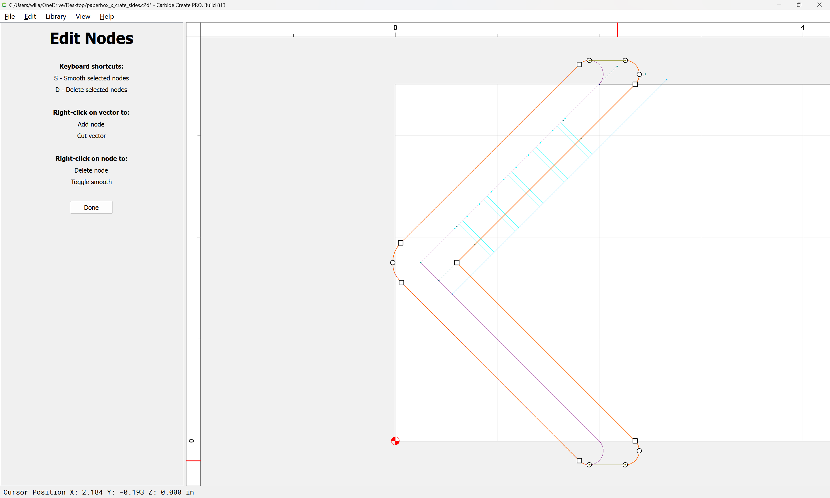
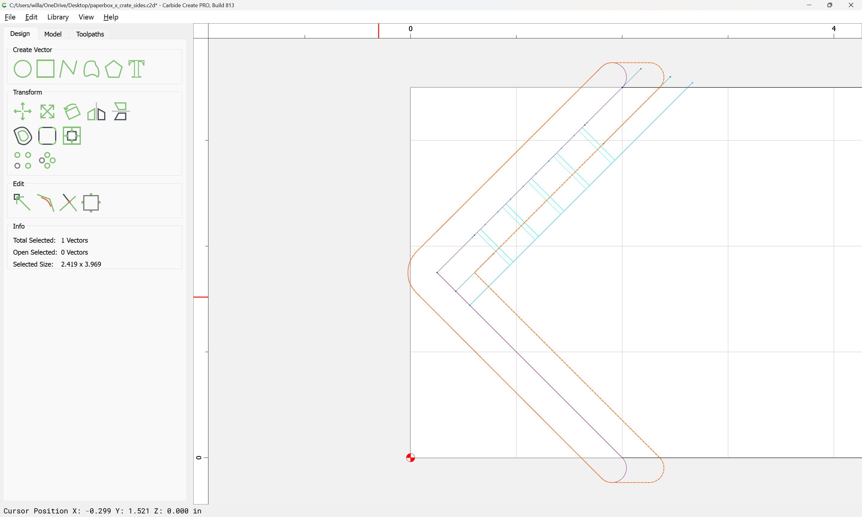
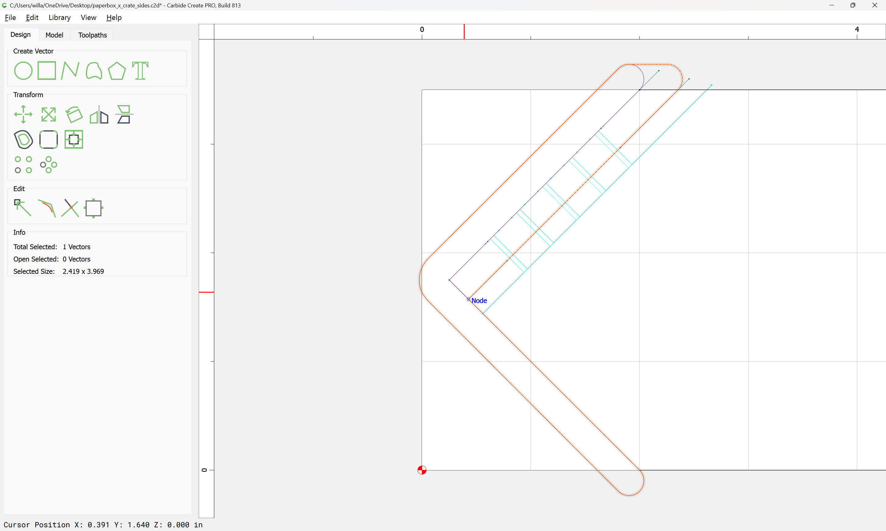
Select the two outlines and go into Node Edit mode:
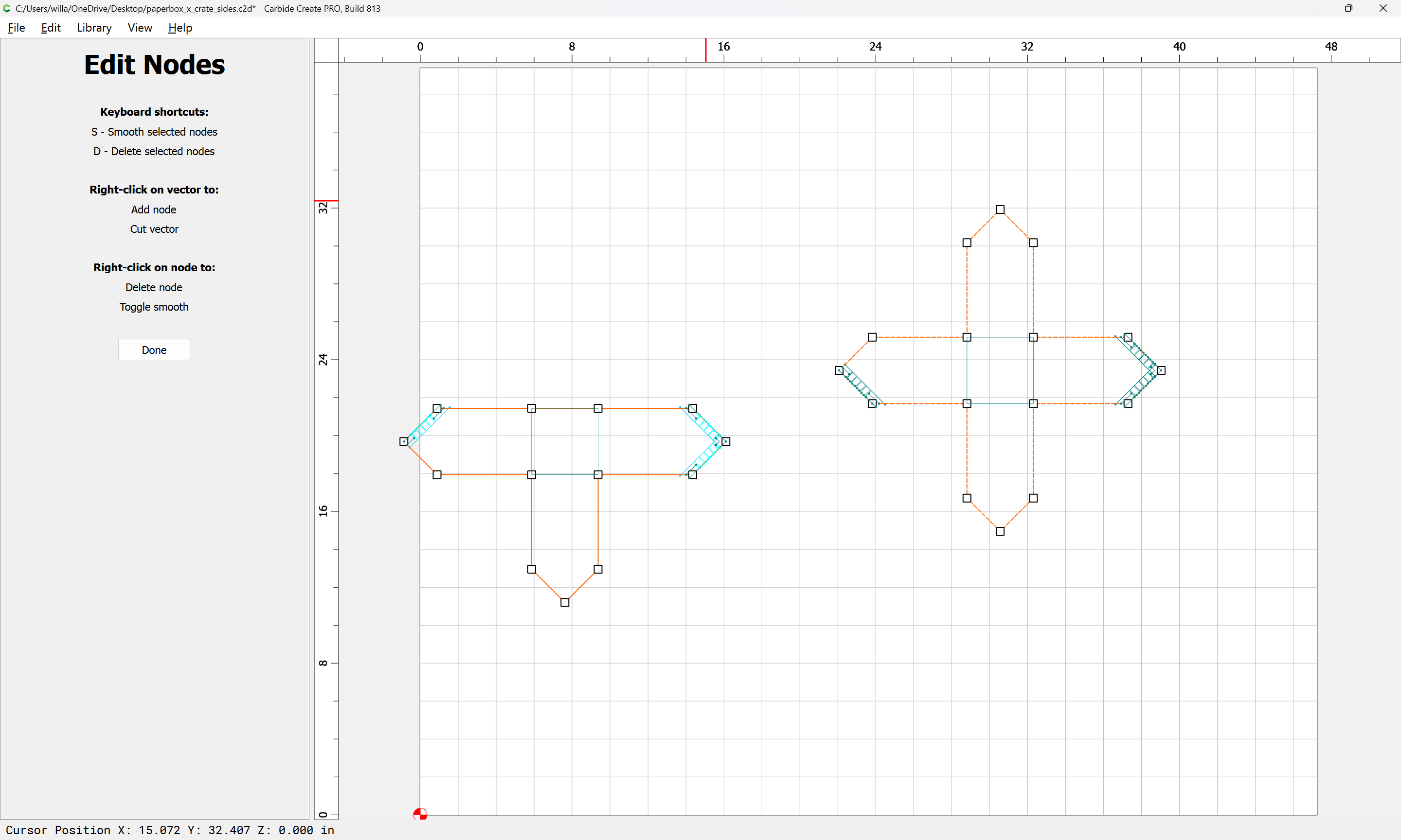
and remove the redundant portions:
Done
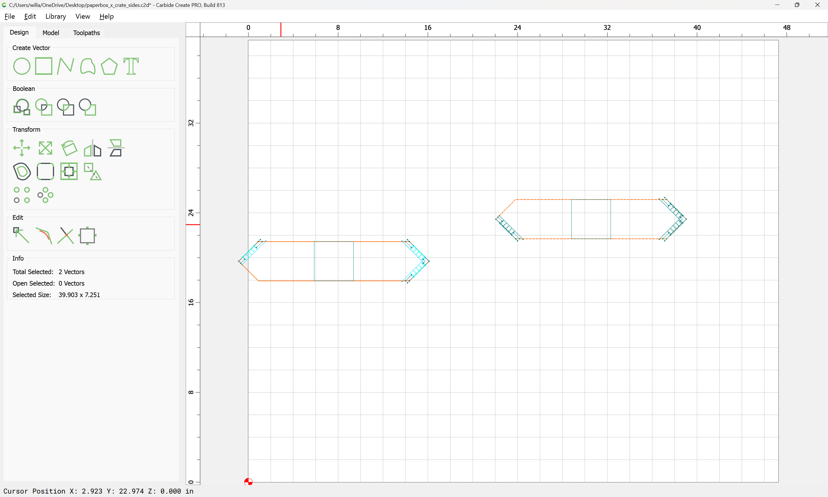
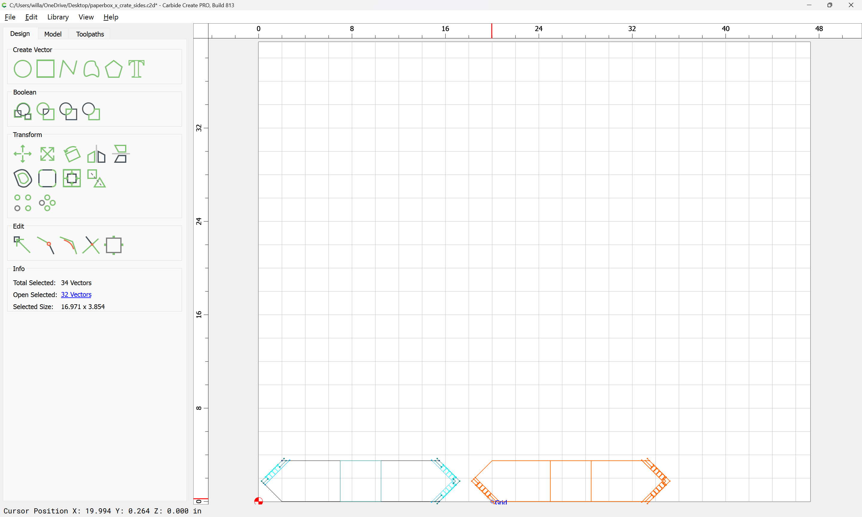
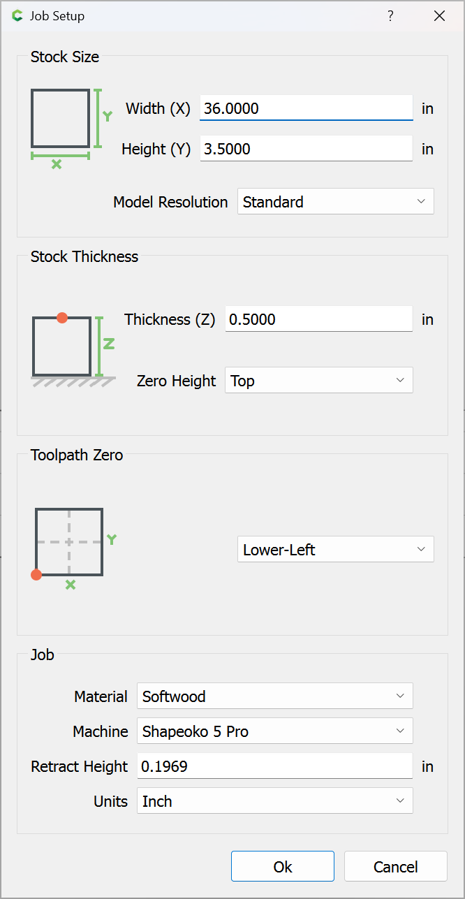
Arrange so that the parts can be cut from a board:
and reduce the Stock Size in Job Setup:
Select the rectangle for the half-lap:
and make it tall enough to unambiguously cross the part outline:
Duplicate the part outline in place:
and select both the duplicate and the rectangle:
and use Trim Vectors:
To remove the rabbet area:
OK
OK
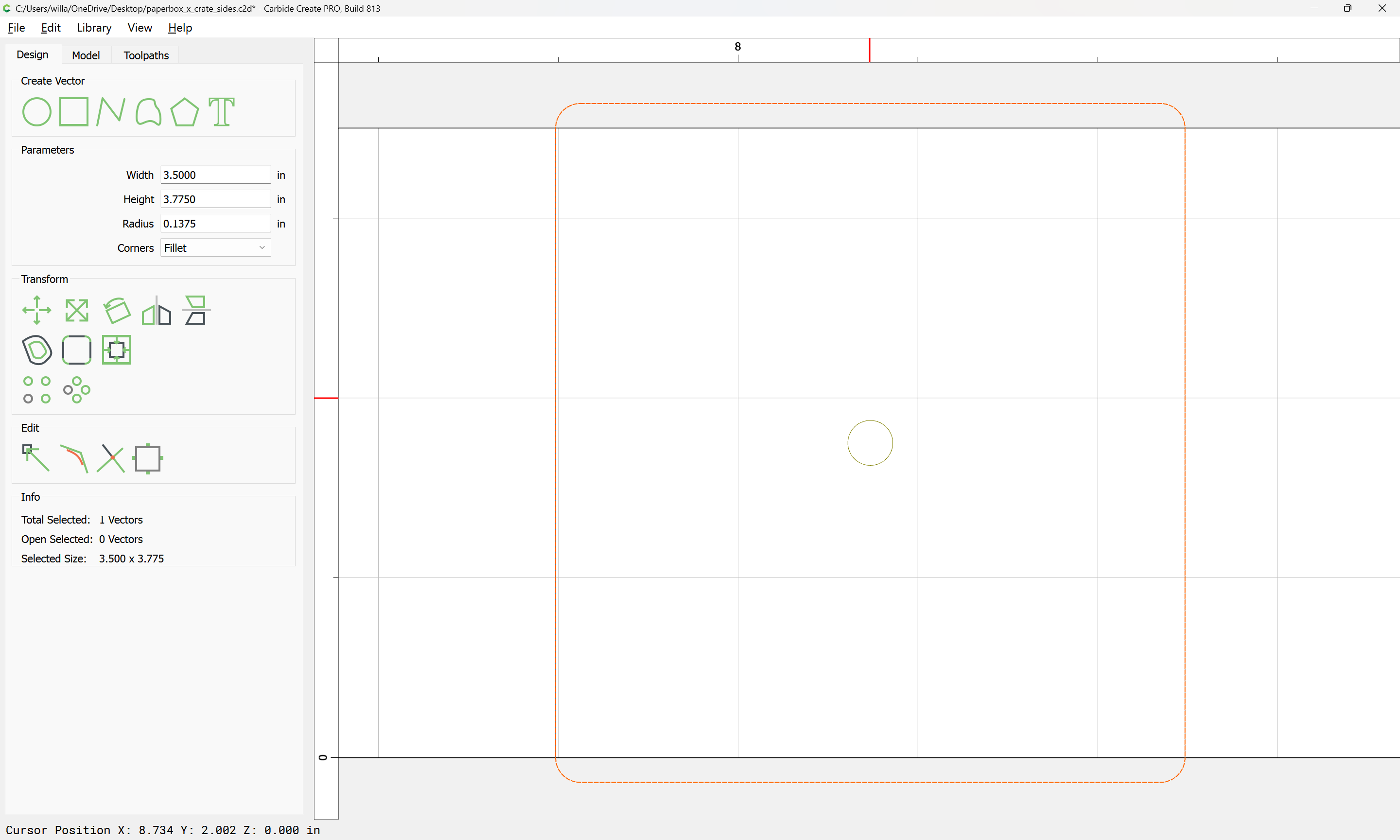
Then again, since this is a board, the outline approach isn’t quite what is wanted — instead, change the height of the rectangle to allow cutting the rabbet directly:
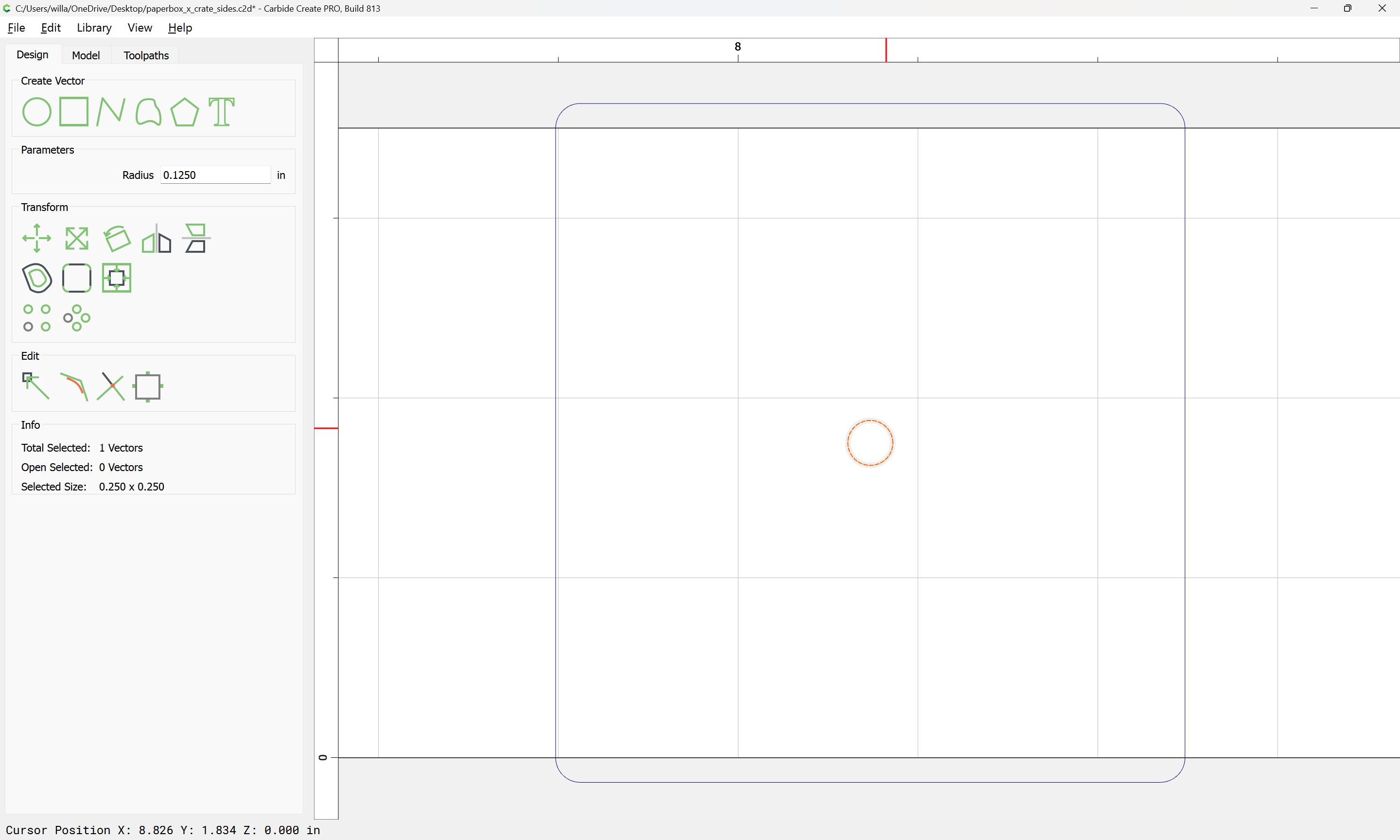
Then, draw circles which are endmill diameter plus 10%:
add a connecting line:
Select both, and rotate:
Reposition:
and then draw in geometry to allow drawing a pocket to cut the end:
(probably the Midpoint on a circle quarter could have been used instead)
Select the drawn geometry:
and use Trim Vectors to remove what is not wanted:
Done
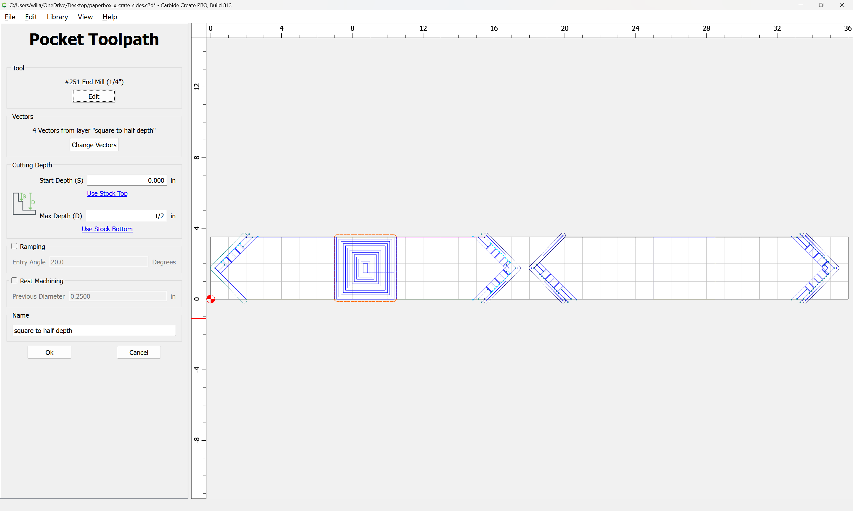
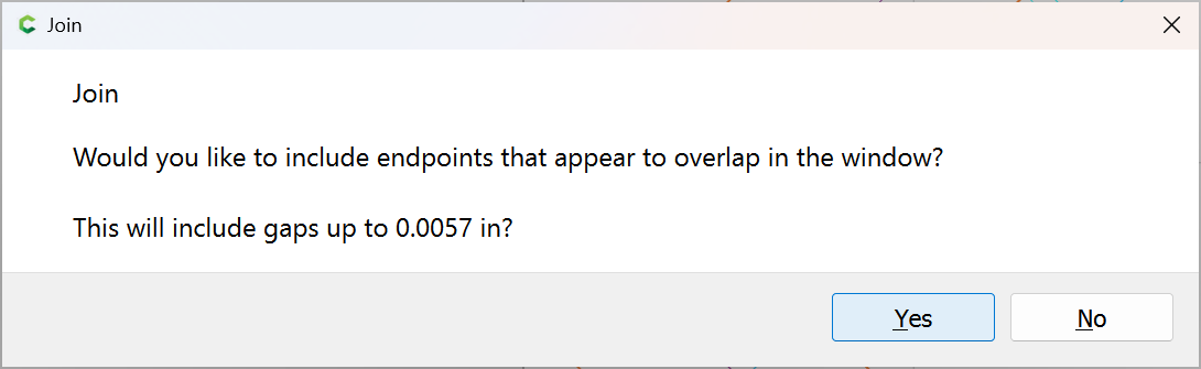
Join Vectors
Yes
Create two new layers:
and move each piece of geometry to the correct layer and then create toolpaths.
WillAdams
February 3, 2025, 12:06am
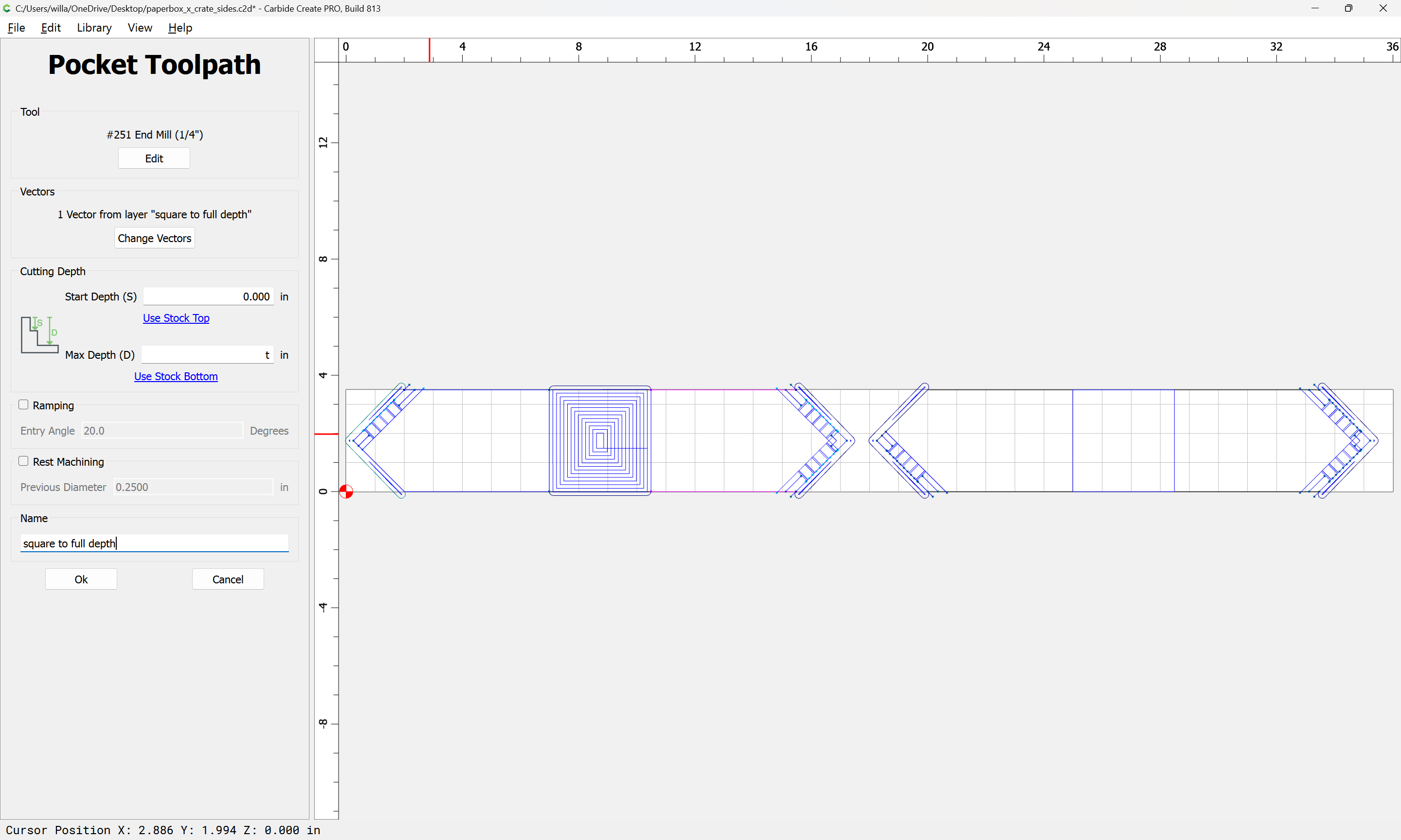
12
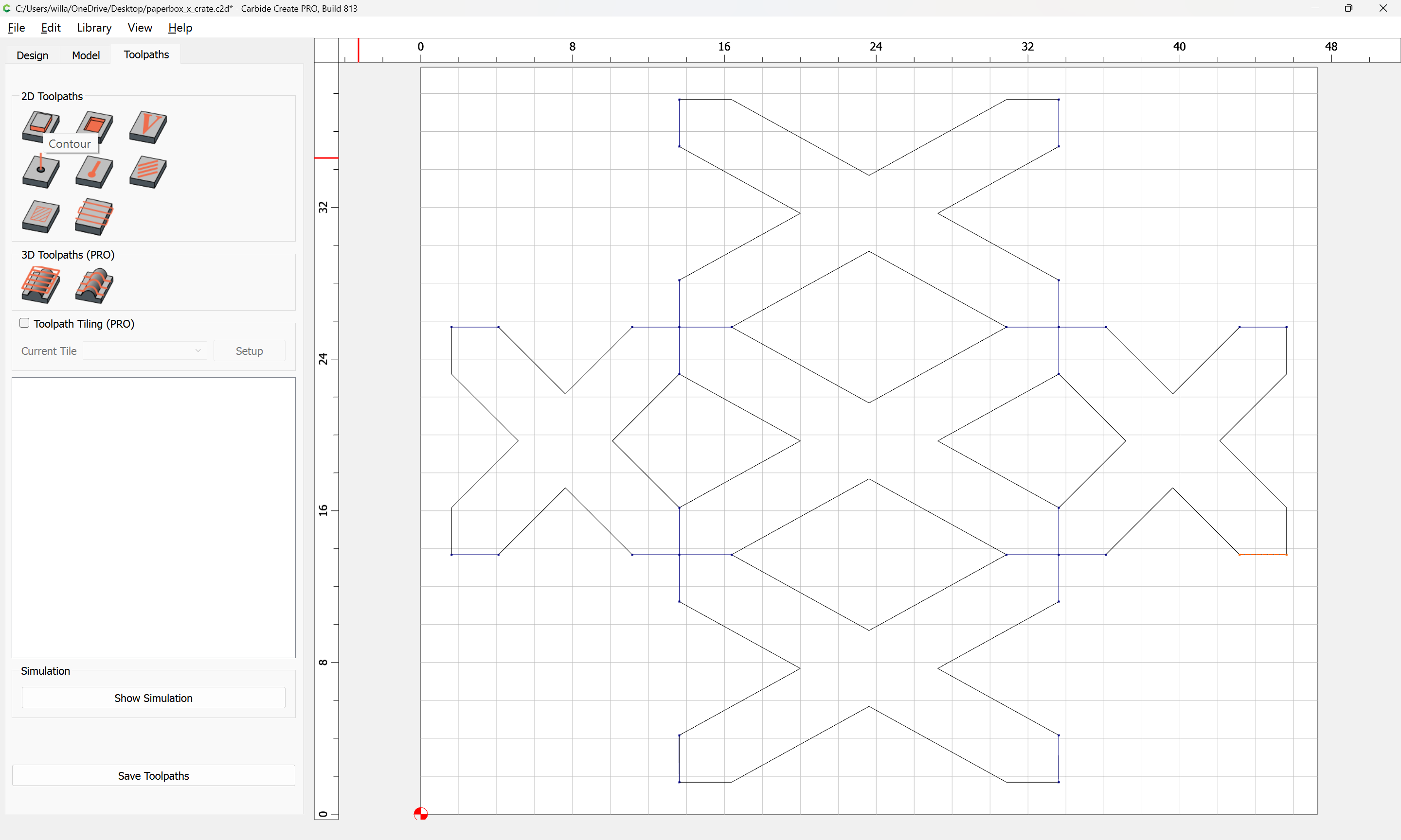
The toolpaths are quite straight-forward:
Except apparently, the geometry isn’t wide enough:
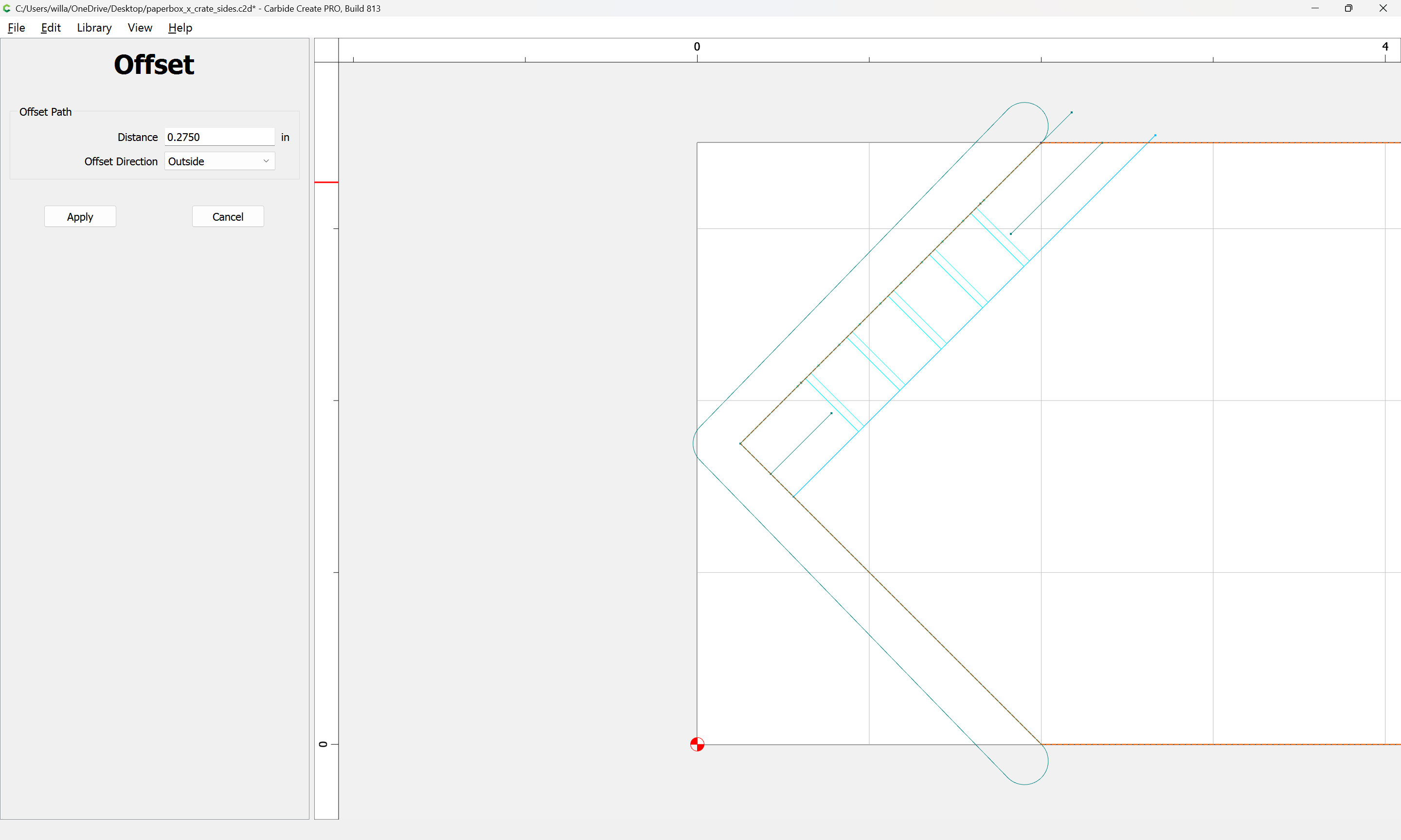
Offsetting the original geometry:
Shows how things don’t quite line up:
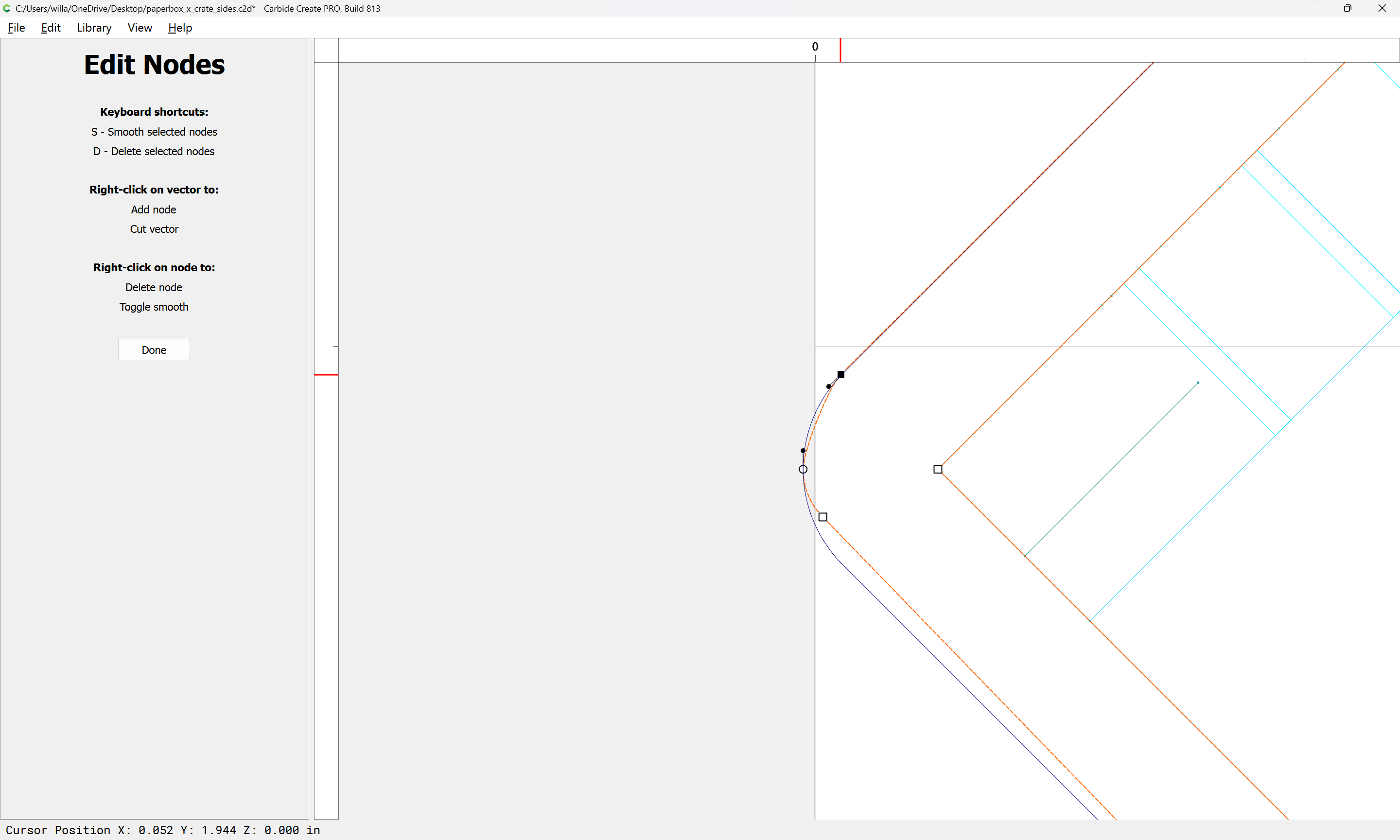
a quick bit of node editing:
addresses this:
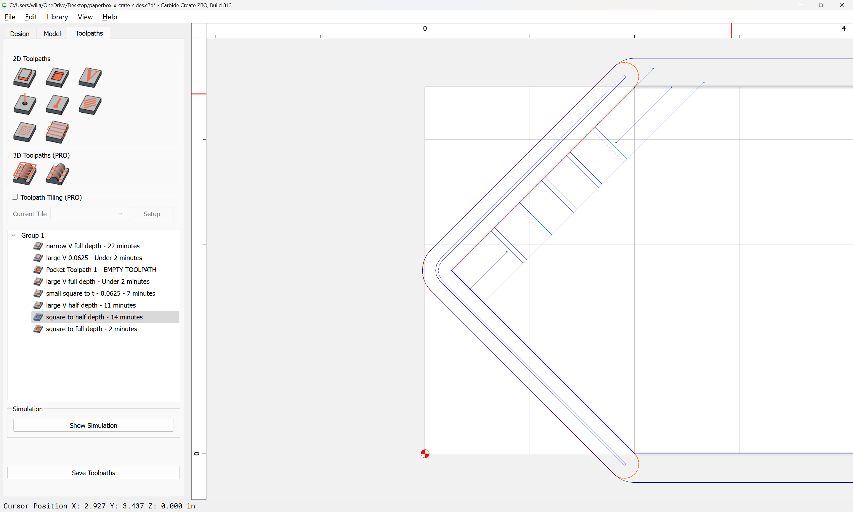
Which then previews as:
Note that it will be necessary to work up a way to do a second operation on the board without a half-lap to add that cut on the opposite side.
Repeat for the other parts.
WillAdams
February 4, 2025, 2:31am
13
Some lines may need to be extended:
Additionally, it will be necessary to add one further toolpath (and geometry to define its extent) — removing the top of the fingers so that they will not interfere.
This is done by making a new layer:
duplicating the geometry:
and using Trim Vectors to remove what is not wanted:
OK
Drawing in lines to connect the parts:
Deleting the unneeded remainder:
and then Node Editing to clean up the trimmed elements:
Done
Select the elements which describe the region for the toolpath:
Join Vectors
Yes
and edit things as necessary to fix the area encompassed:
1 Like
Redlander
February 4, 2025, 12:36pm
14
I appreciate the time you take to put into these projects you demonstrate for the community.
Thank you!
WillAdams
February 4, 2025, 12:40pm
15
If you’ll let me know where things aren’t clear we can review it.
The big thing is, once I’m done I’ll post the files for folks to review, so it should be possible to deconstruct them/examine them in detail.
Hopefully, I’ll get some parts cut — took the day off for that, we’ll see.
Redlander
February 4, 2025, 12:56pm
16
Thanks, my proficiency with just the keystrokes for using CC is getting better. I have downloaded some files for reference. So far I am creating my own to learn the software. It was a good exercise to design/cut a reference fence for tile operations and figuring out how to trim it parallel to the Y axis with my 1” cutter to give me 48.5” between it and the bitsetter. Several pieces of random “48 inch” wide stock measured yields up to 48-3/8’s” wide and I didn’t want to have to remove the bitsetter just to tile 48” wide.
1 Like
WillAdams
February 4, 2025, 5:26pm
17
One further consideration is machining the half-lap on the opposite side on one of the parts.
Since one is already machined on the other:
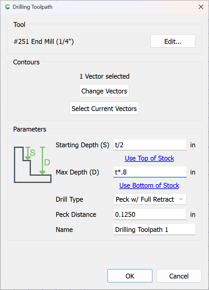
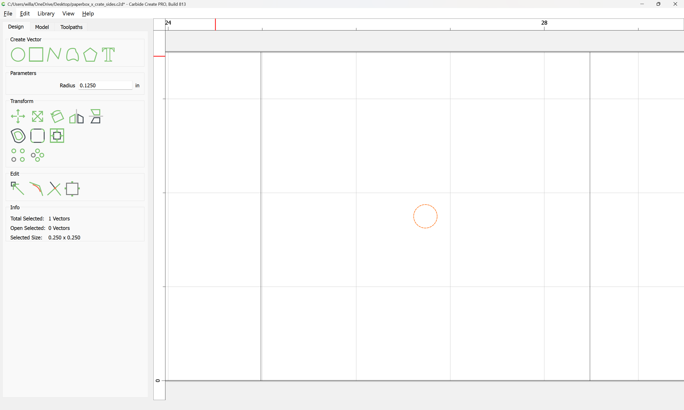
It seems straight-forward to add a circle at the center of that:
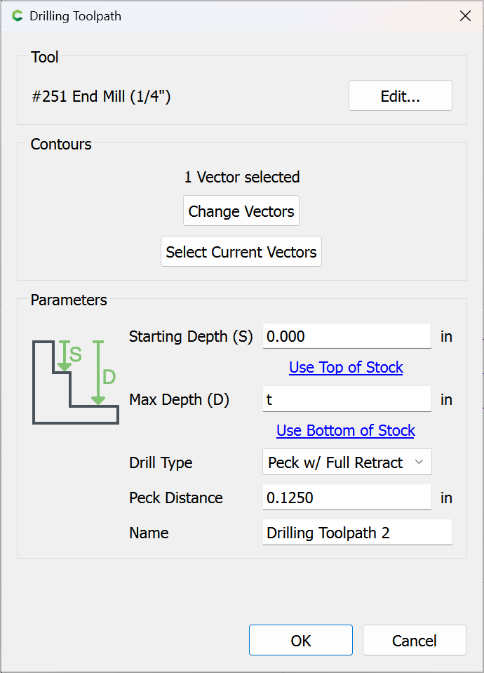
and drill a hole not quite all the way through:
which can be used with a dowel and a matching full-depth hole:
so the order of operations would be:
cut the parts
free the part which needs the half-lap on the bottom
insert a dowel
position the freed part registering on the dowel and the cut half-lap
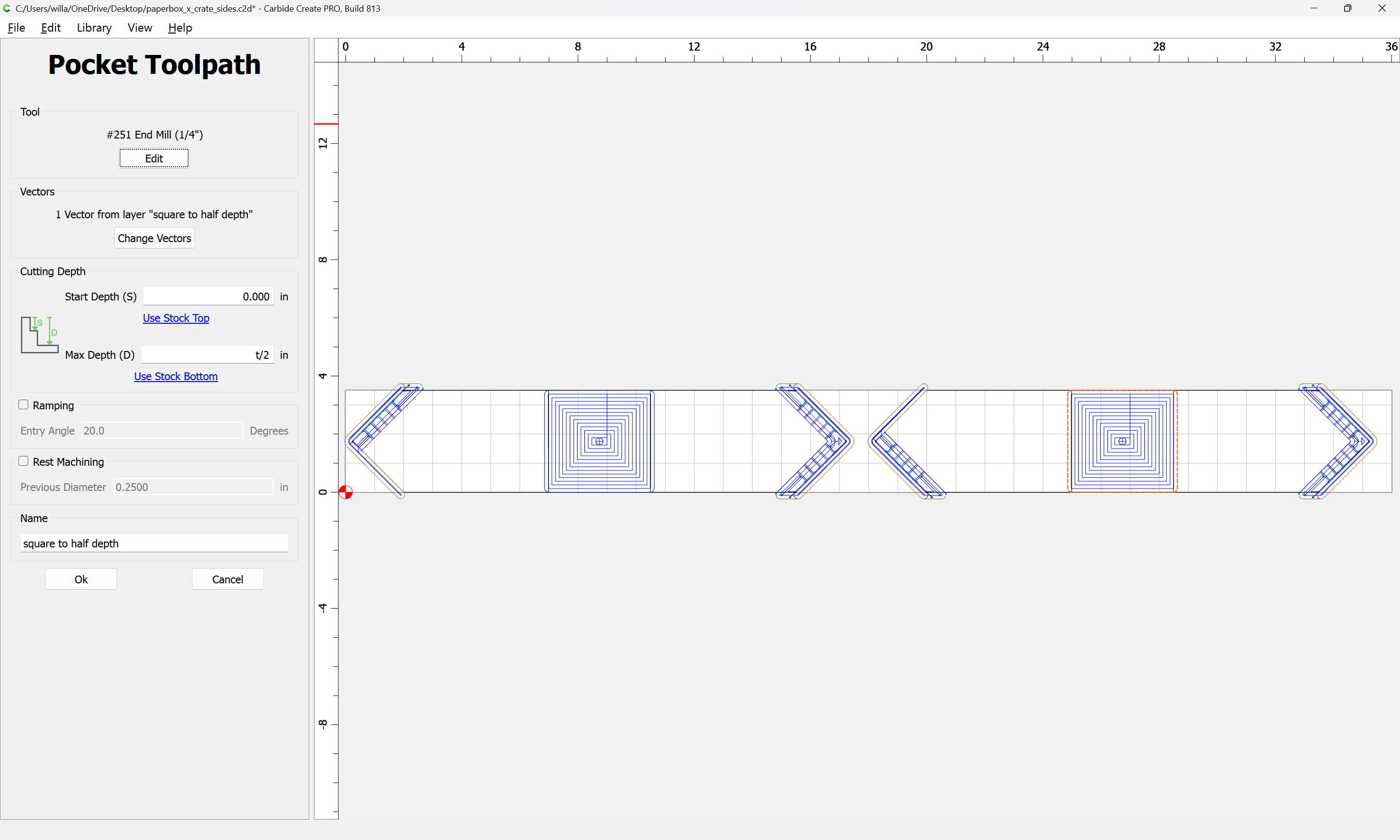
machine a suitable pocket:
(that toolpath will need to be duplicated, renamed, and put in its own group and associated only with that geometry, or a new layer with that geometry on it)
system
March 6, 2025, 5:26pm
18
This topic was automatically closed 30 days after the last reply. New replies are no longer allowed.