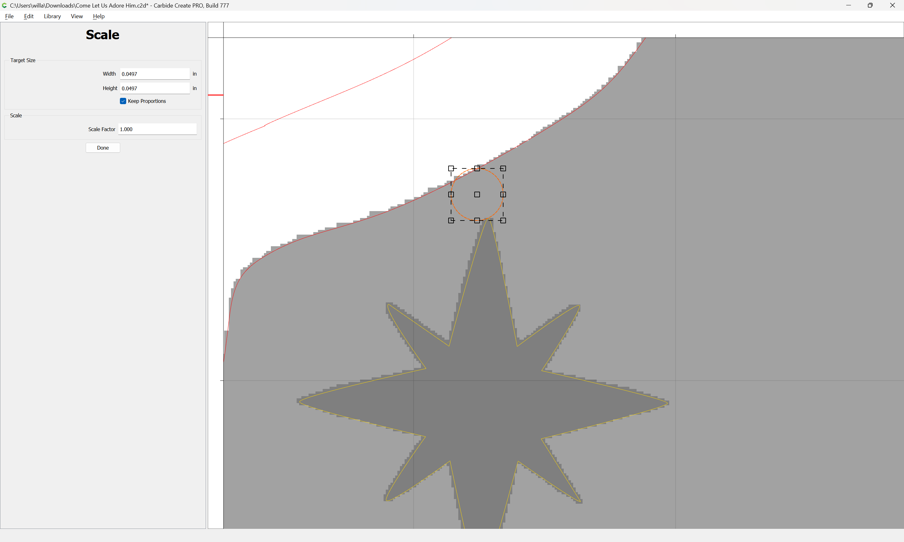
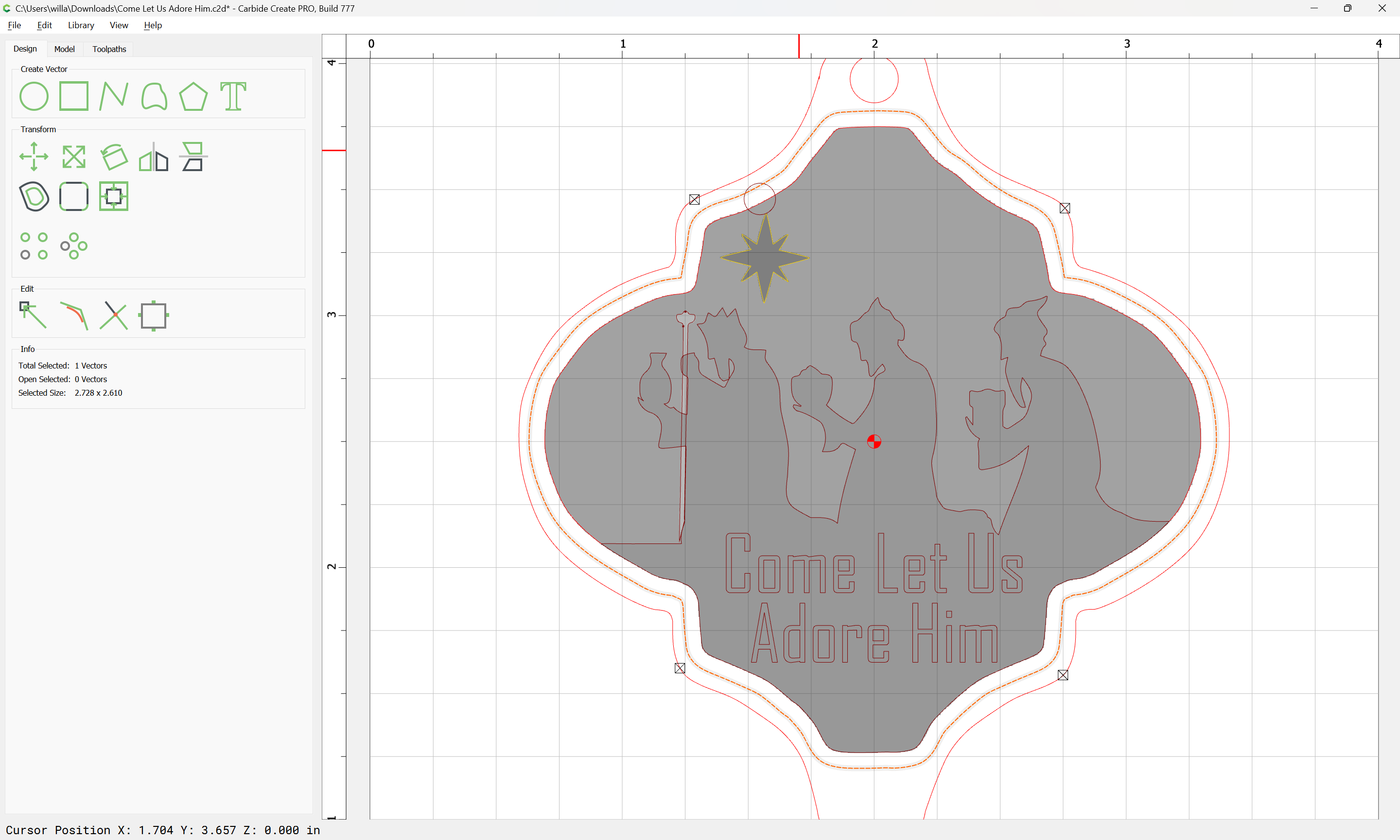
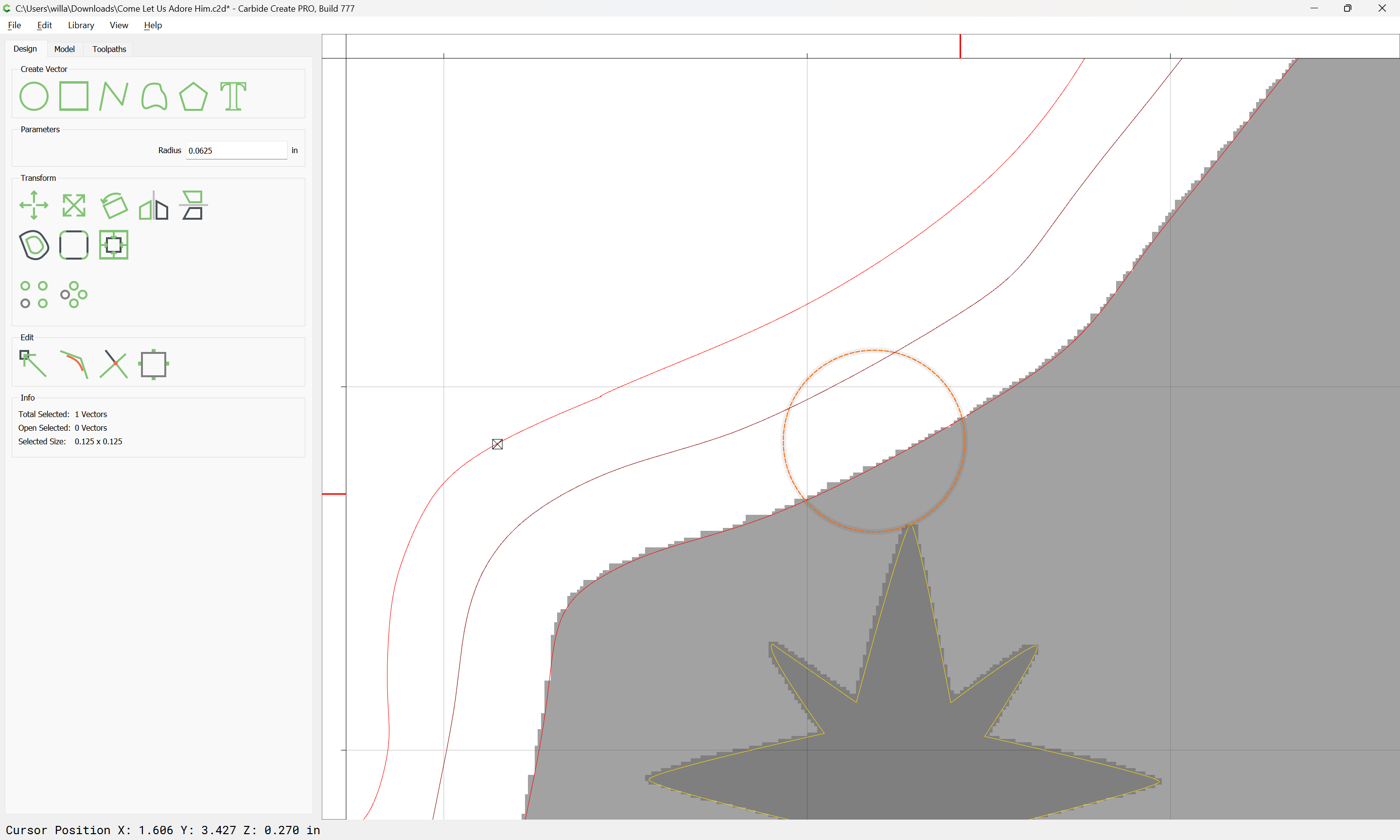
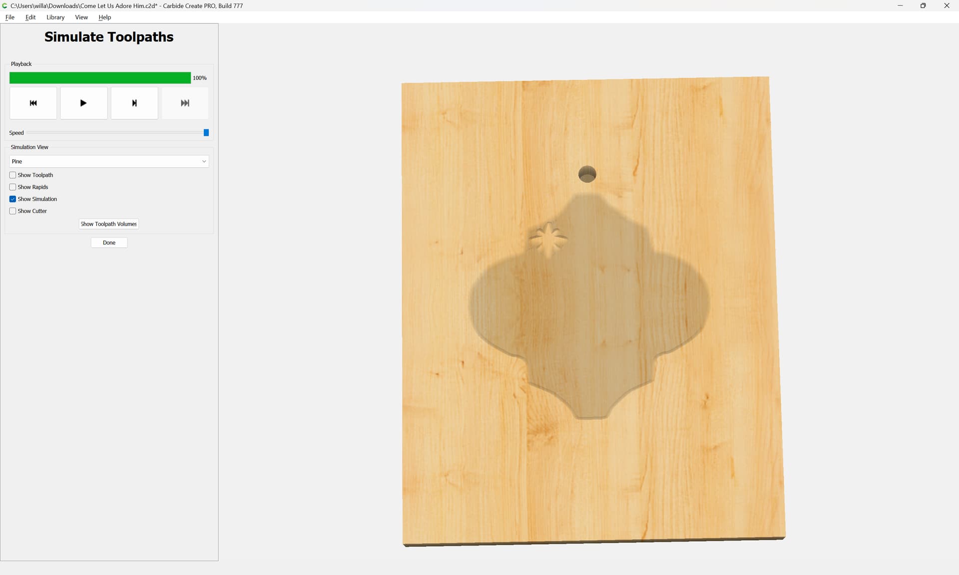
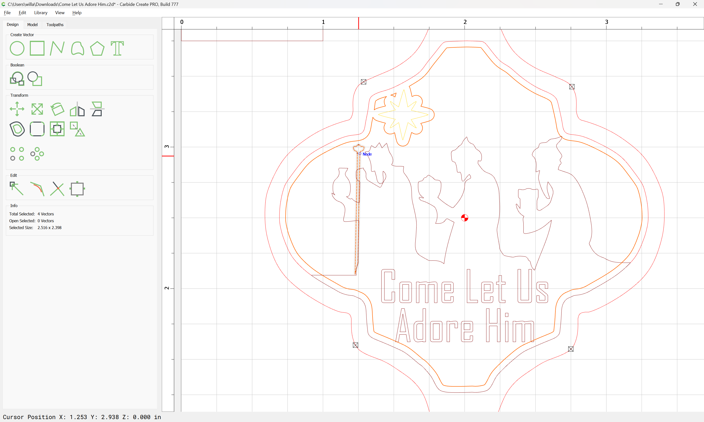
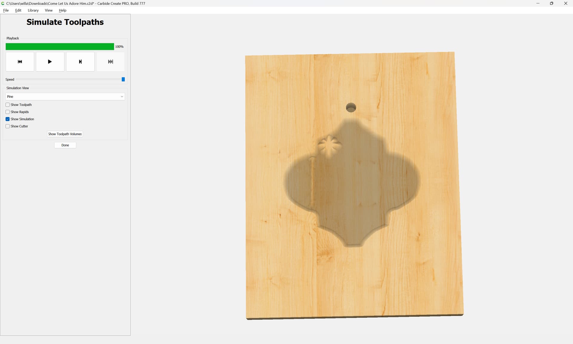
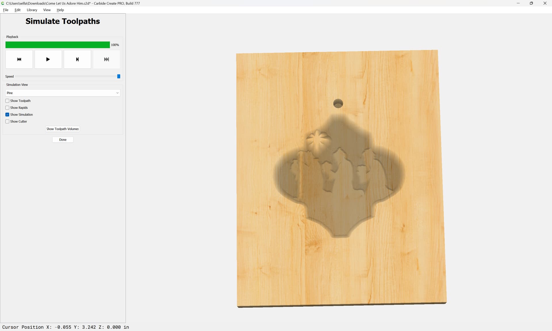
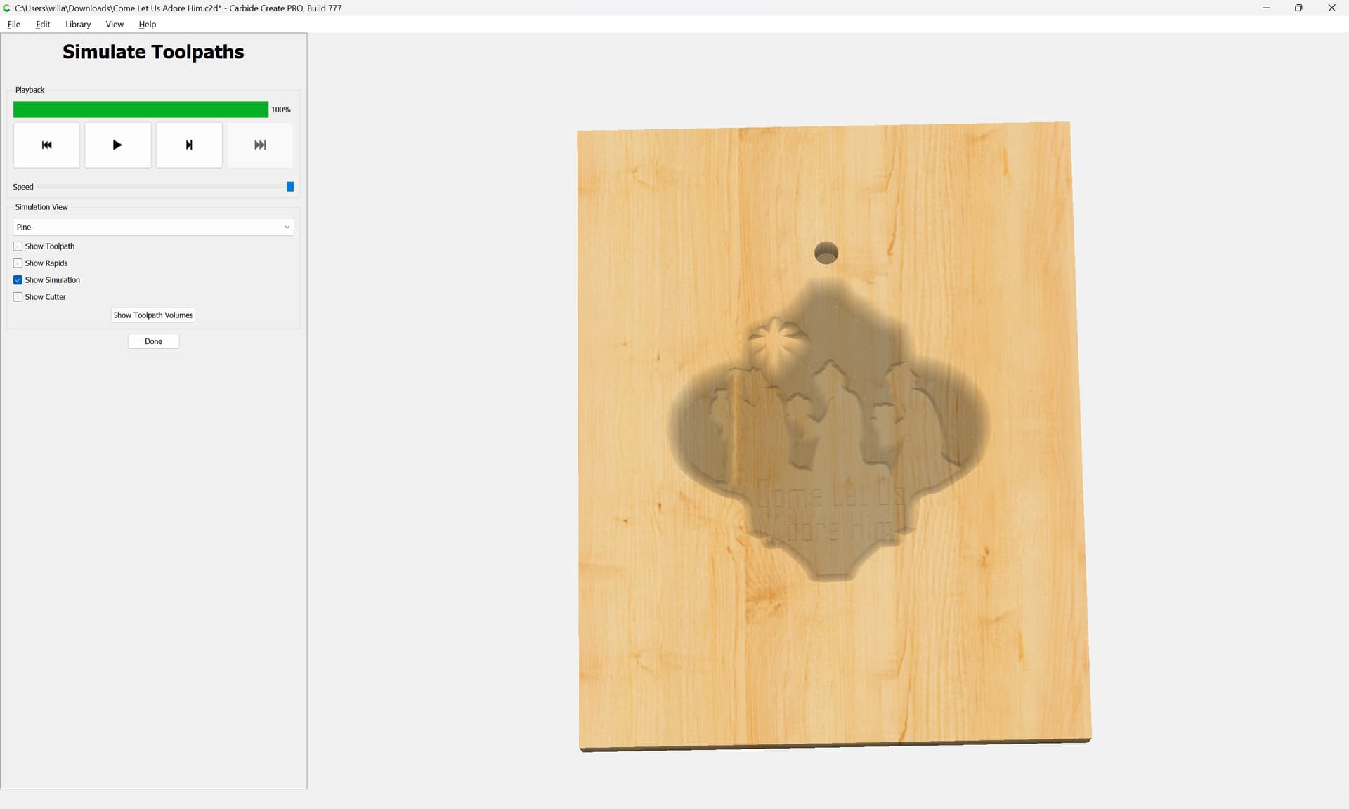
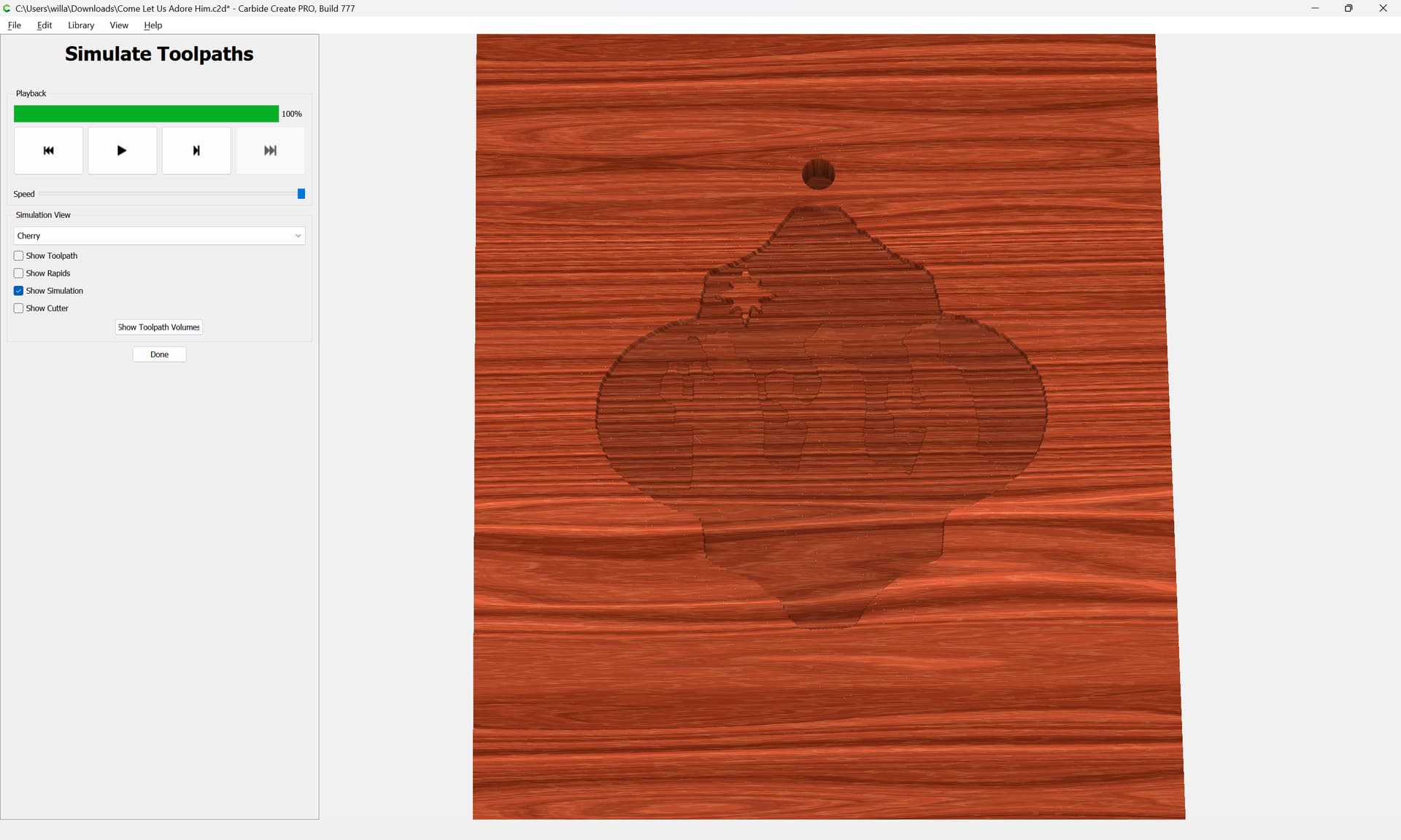
Notice the two nearly parallel “border lines”. The outer one is created by 3D Rough using a 1/8" end mill. The inner line is from 3D Finish with a 1/16" ball nose. On other stuff like this, the Finish Pass essentially wipes away the Rough Pass. I haven’t tried cutting this yet, but am wondering if this is just a glitch in the Simulation or if I have a different problem. I’ve tried tweaking a number of things but nothing has changed the Simulation appearance.
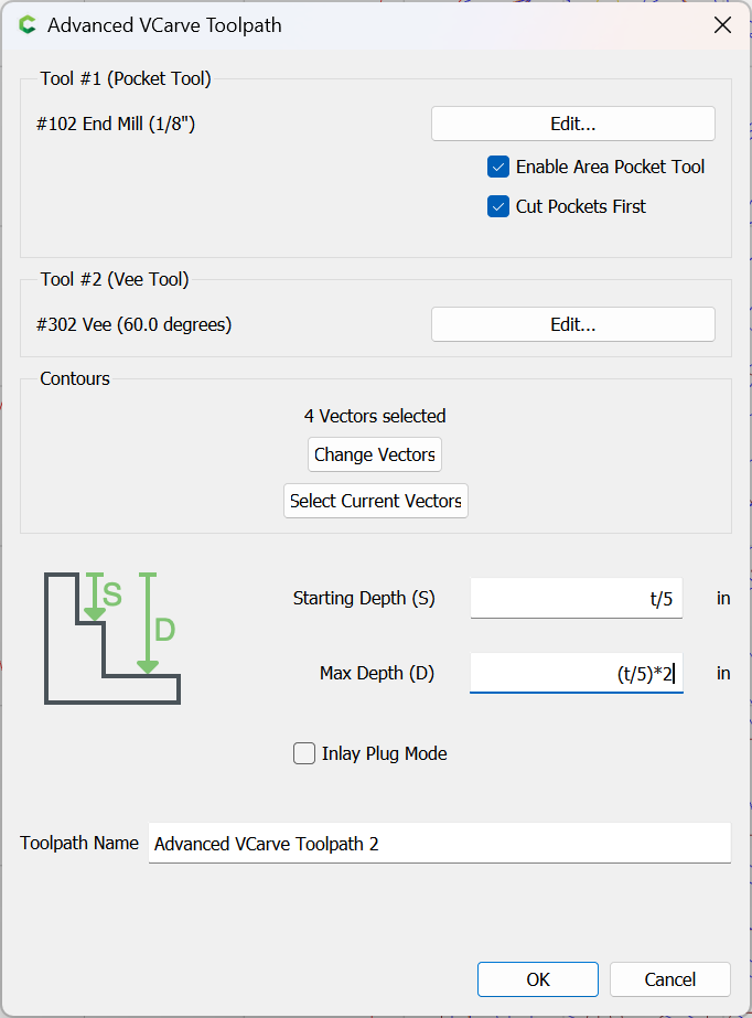
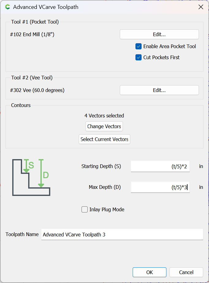
If you want a consistent lip around the design, then you should include it in the 3D model, or cut using “normal” toolpaths, say a series of Advanced V carving toolpaths w/ pocket clearing.
Note that this will require that you draw up the design in profile so as to work out how much the geometry for each preceding level should be inset.
Thanks.
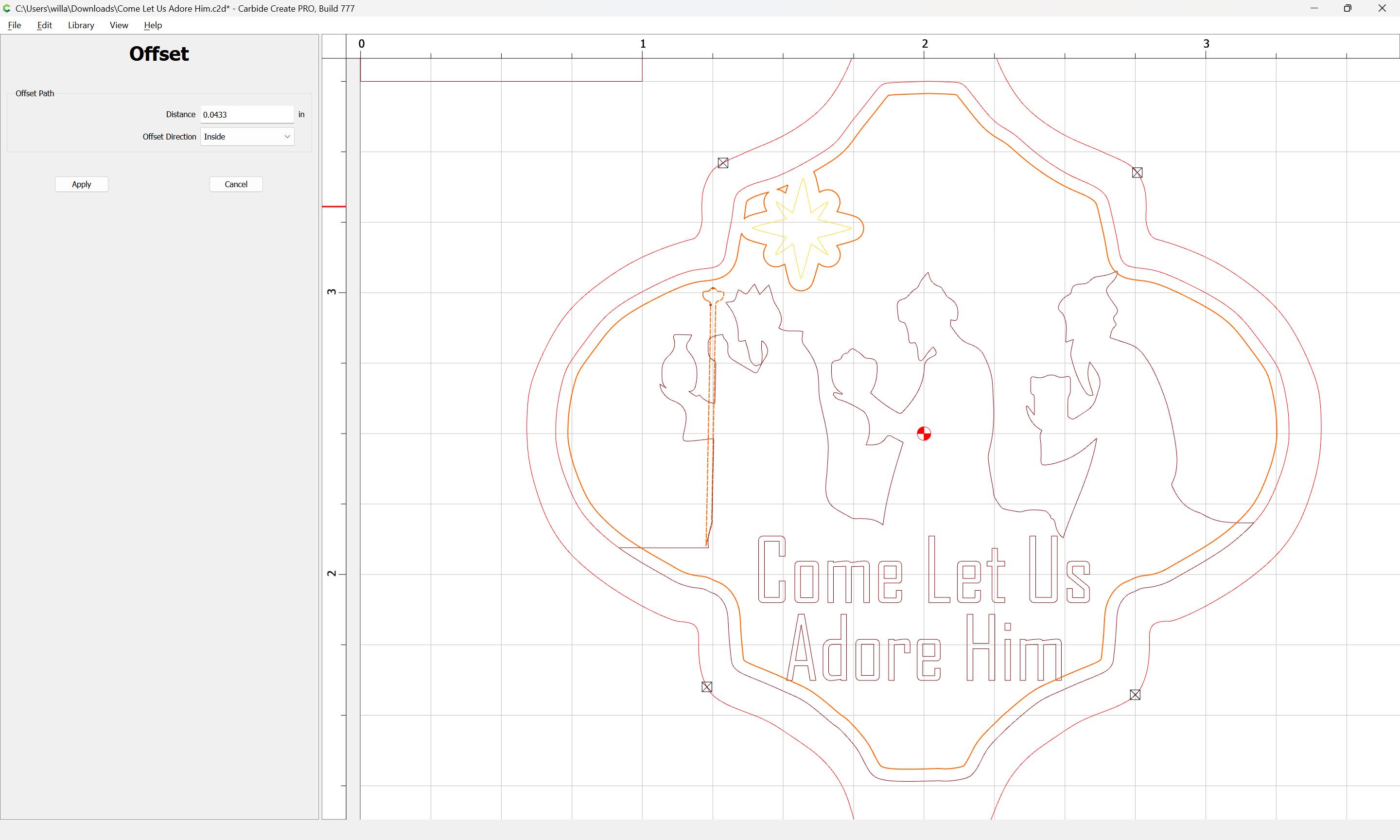
I kind of understand and kind of don’t. My biggest puzzle was why the 3D Rough apparently was cutting further to the outside that the 3D Finish.
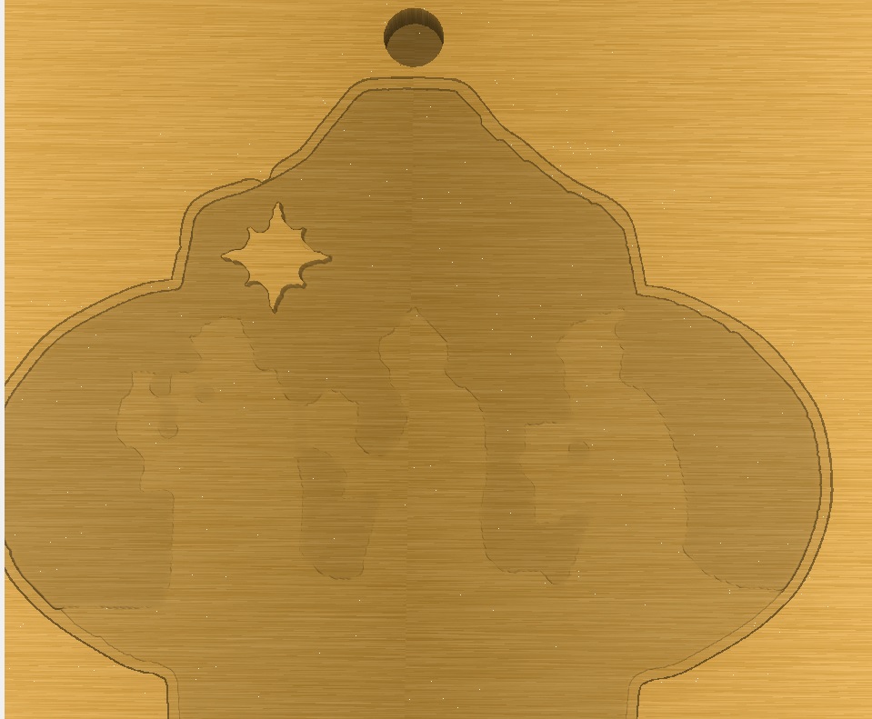
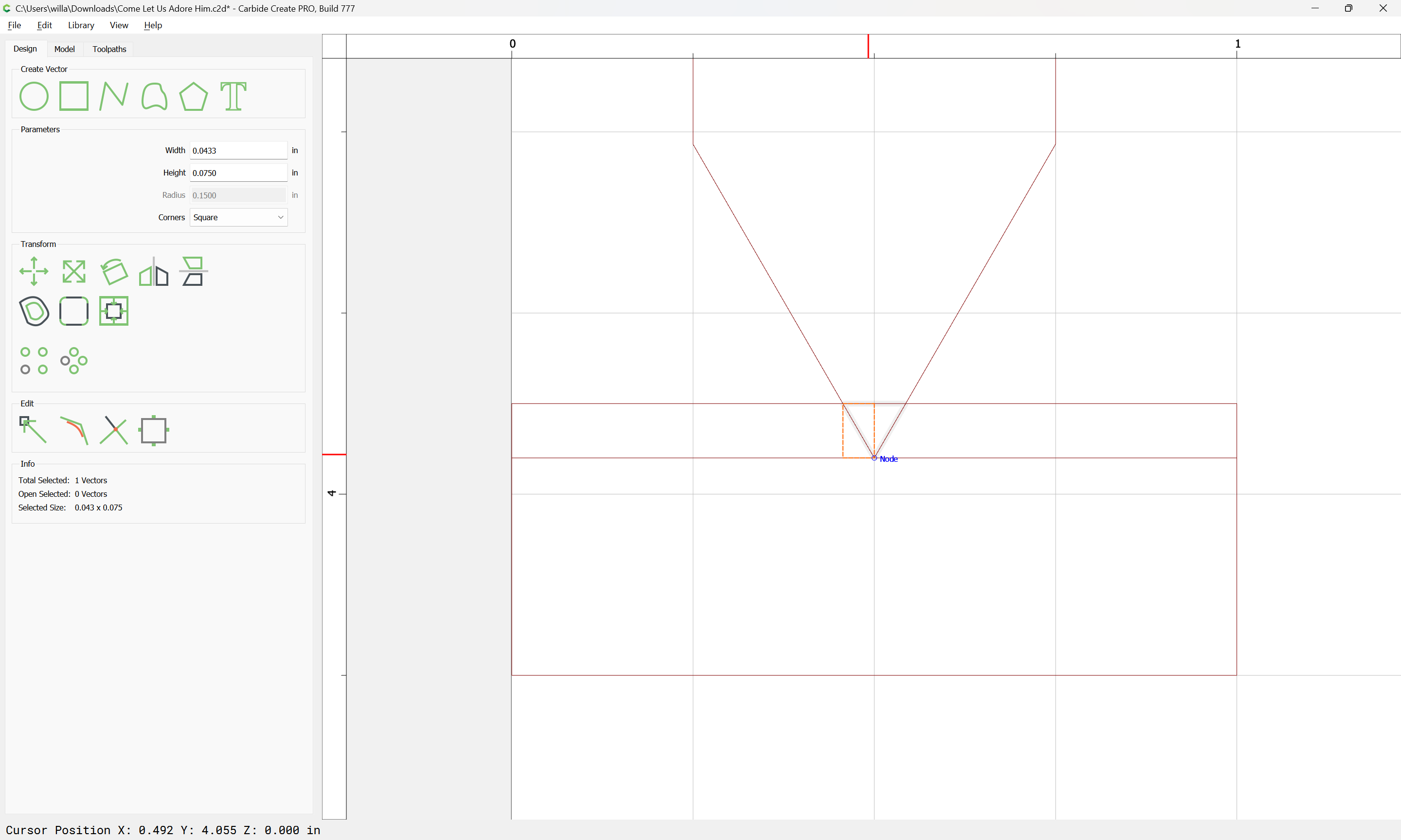
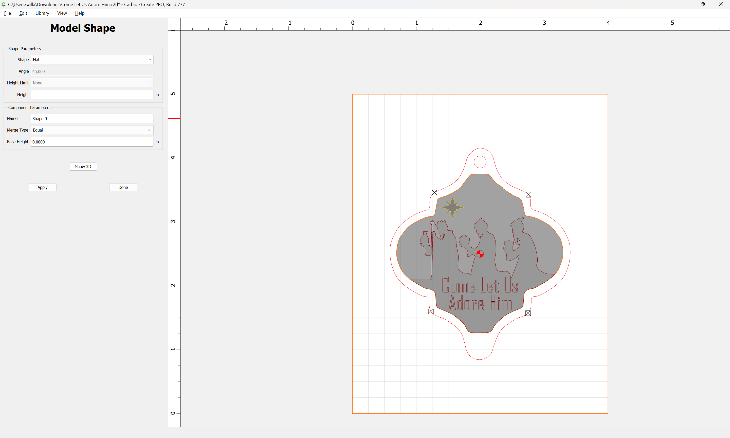
The hiccup near the star I took care of by simply moving the star a few 1/00’s.
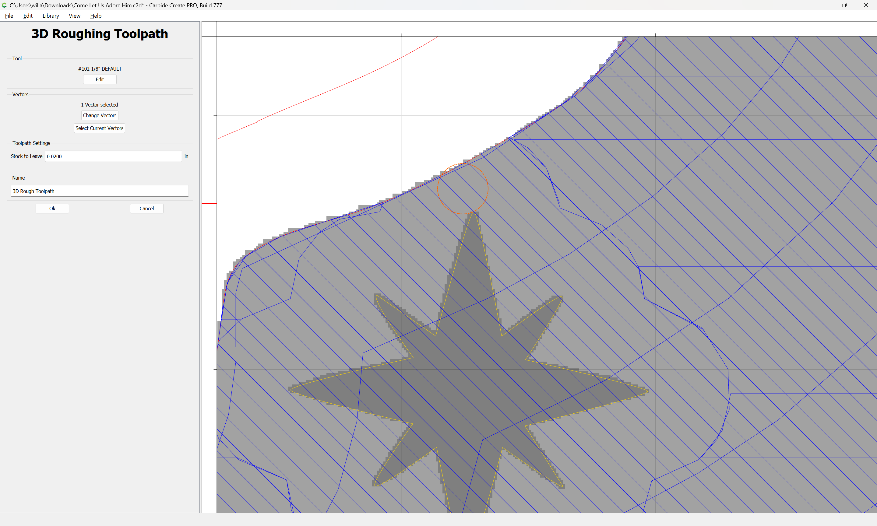
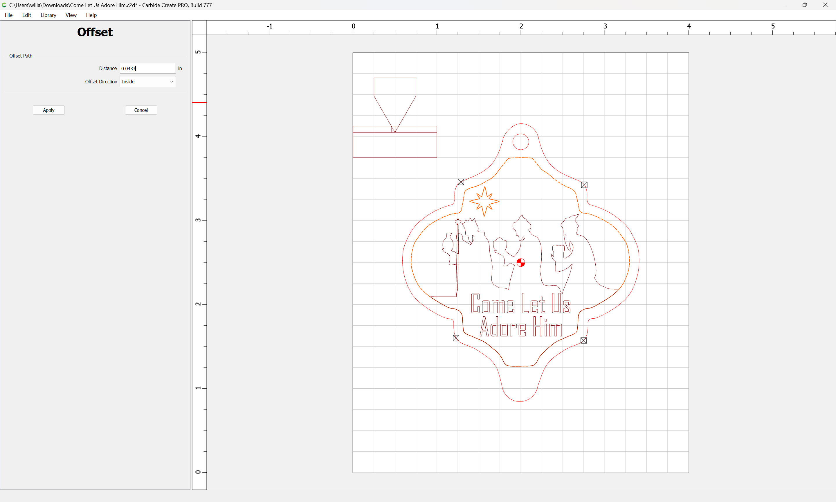
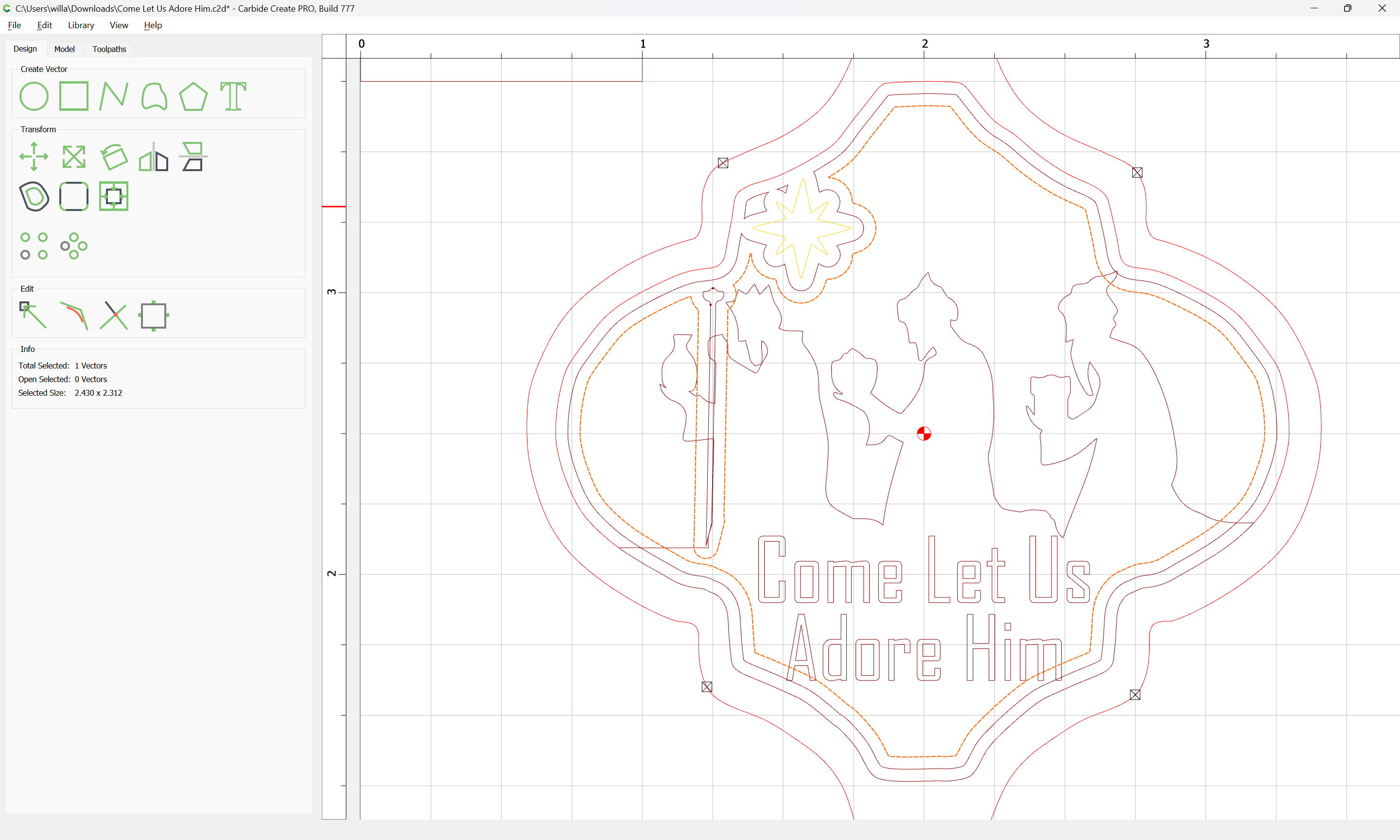
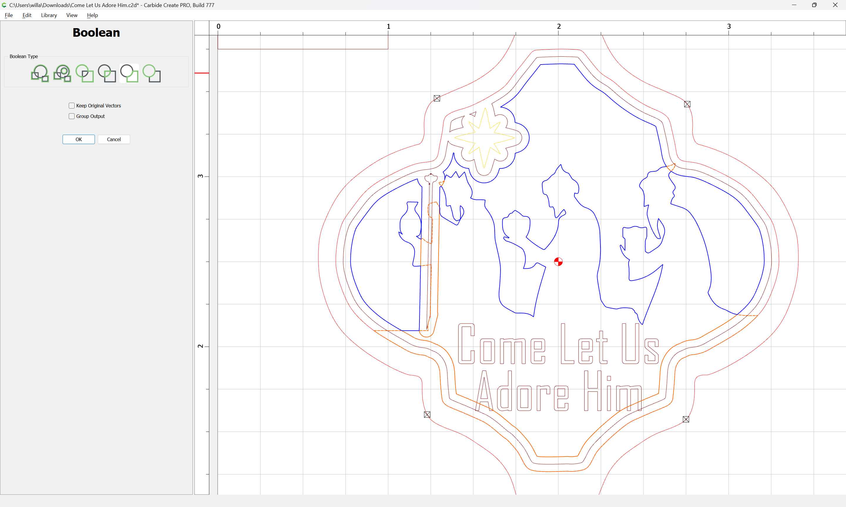
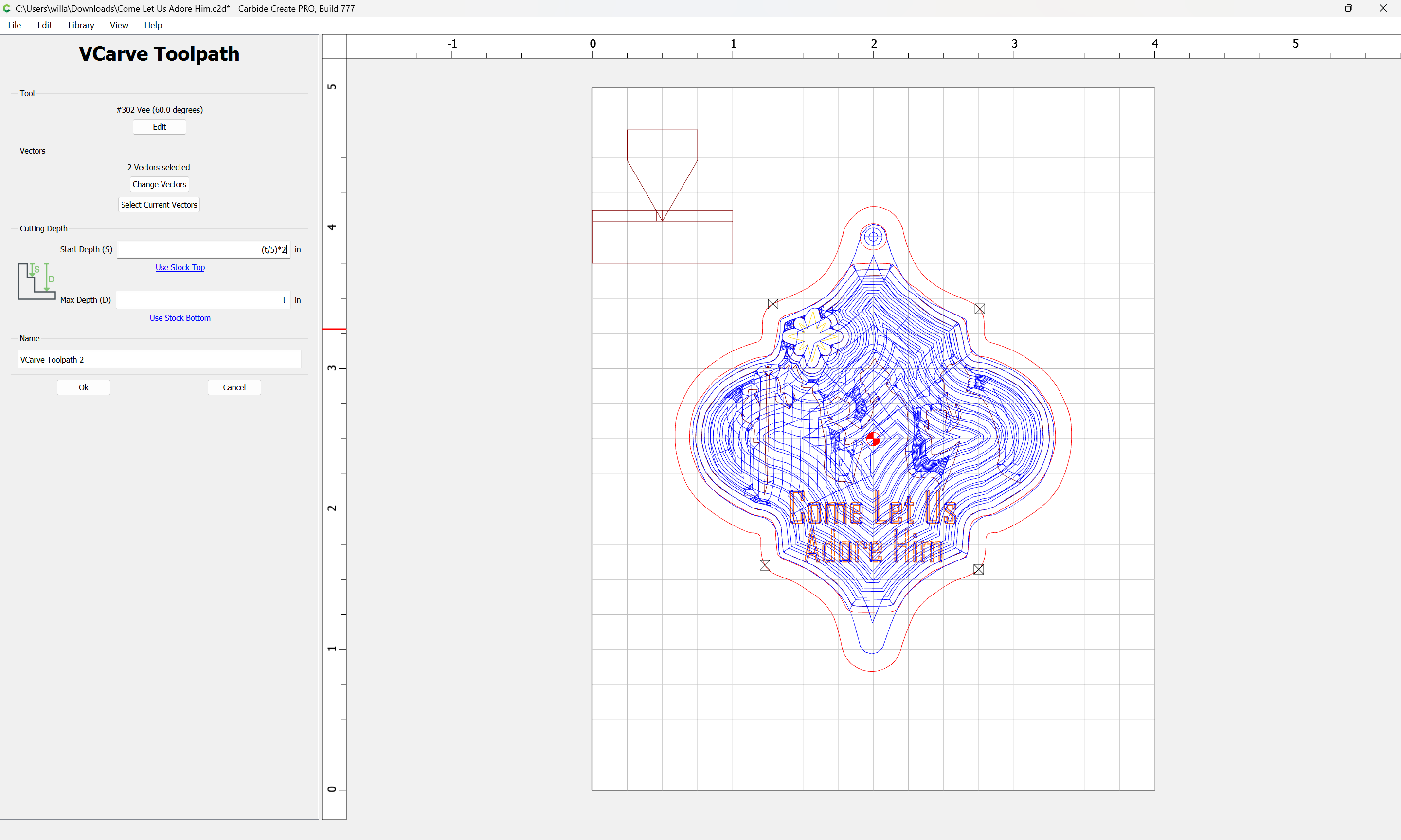
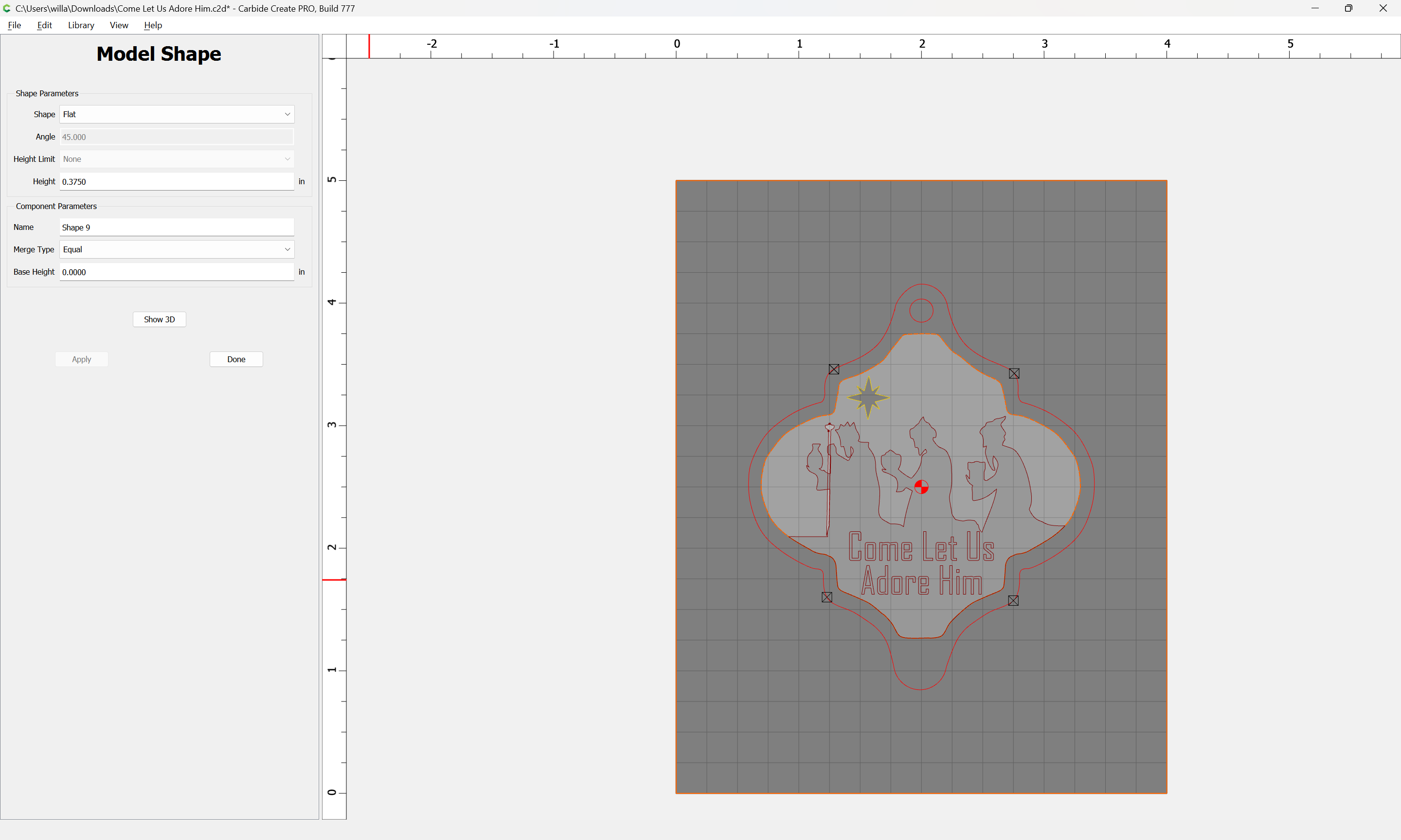
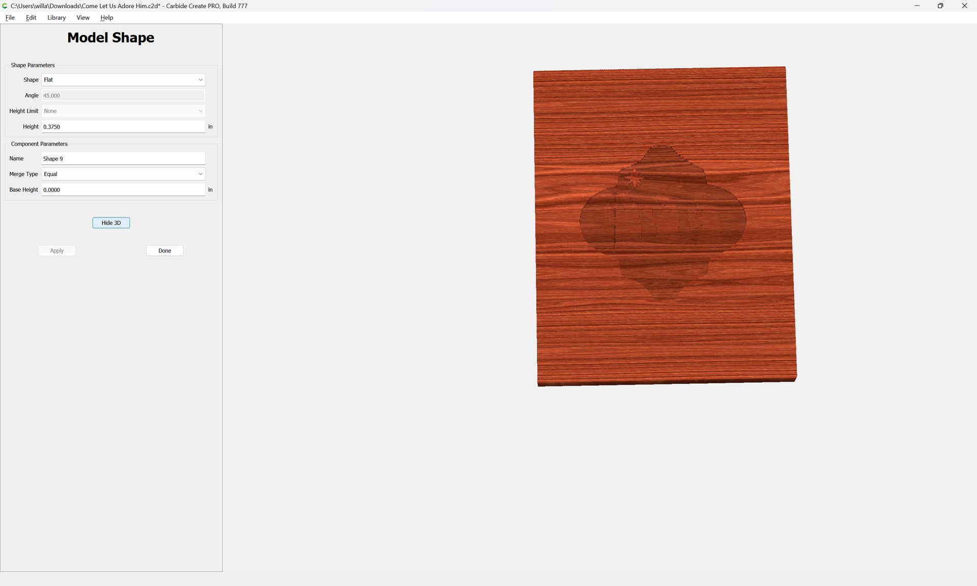
Since part of design is to leave a raised border about 1/10" wide at full height (3/8") I decided to try adding that border within the Model function. Selected the inner and outer border lines and then created a Flat, Ht .375, Equal.
Since I don’t want the Model to do the final cutout (especially when creating a bunch of these on one board) I’ve let the outer border be the controlling vector for the 3D toolpaths.
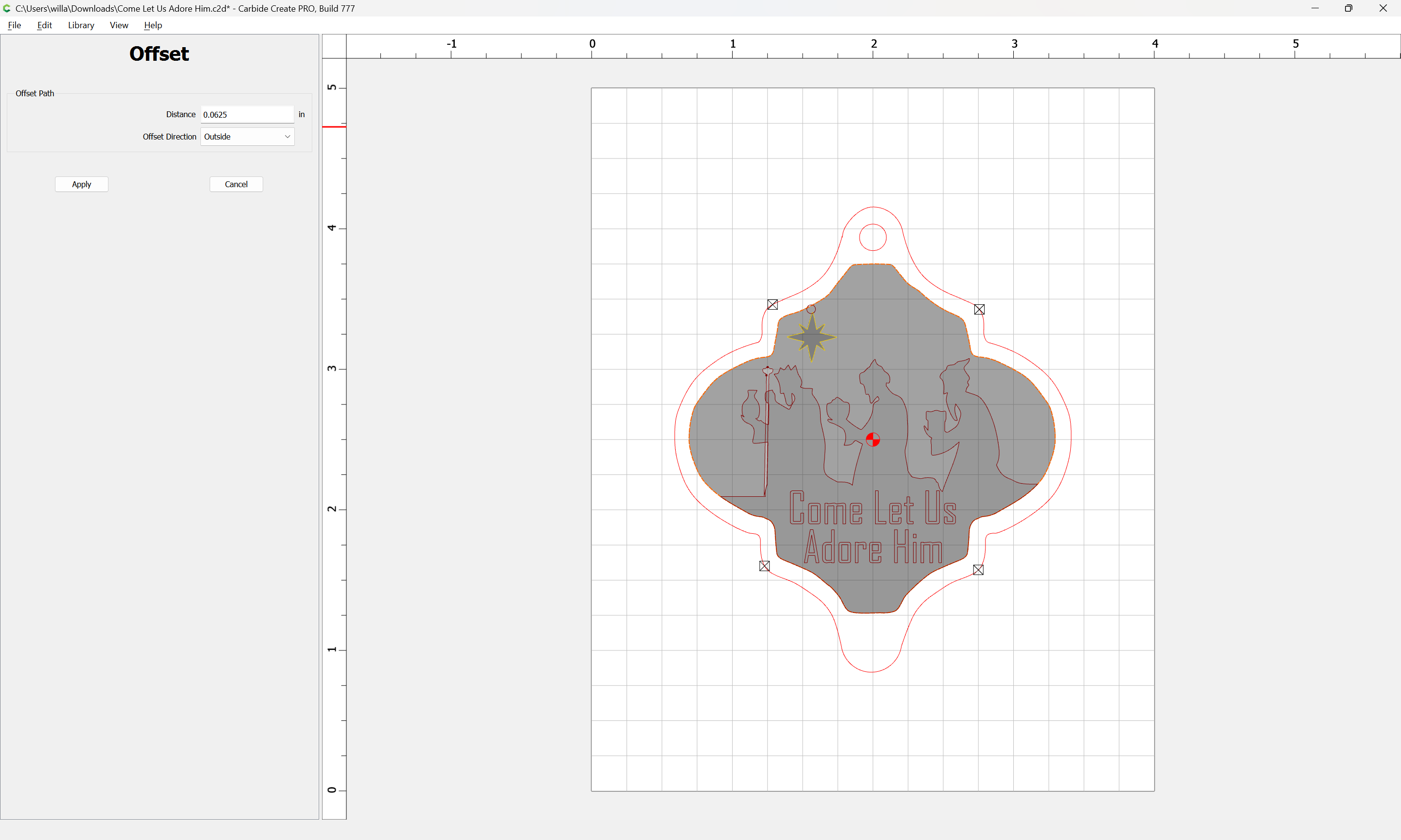
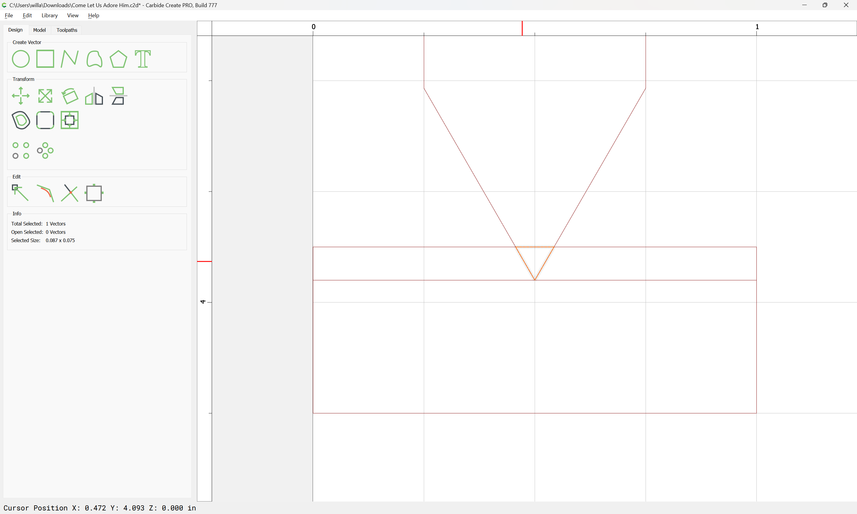
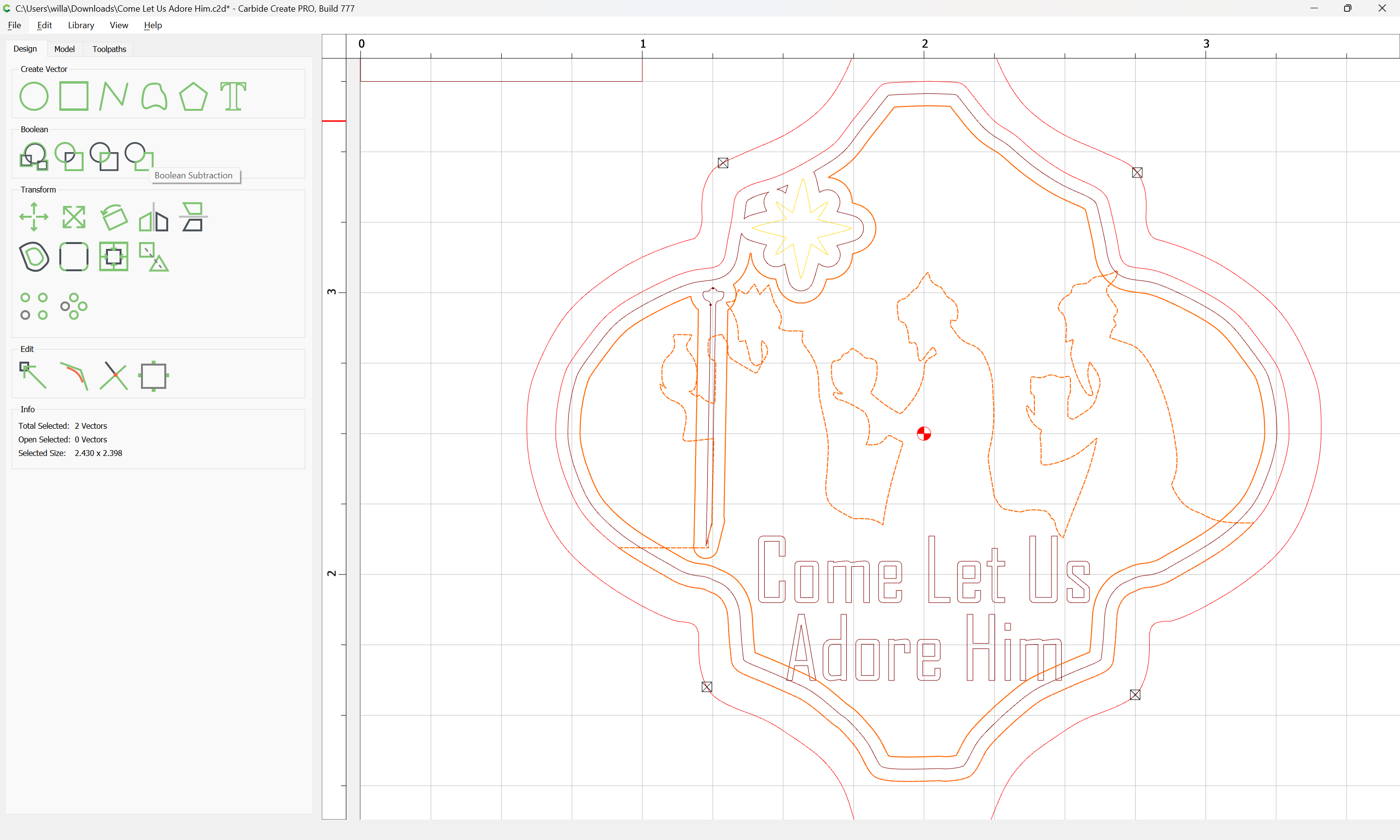
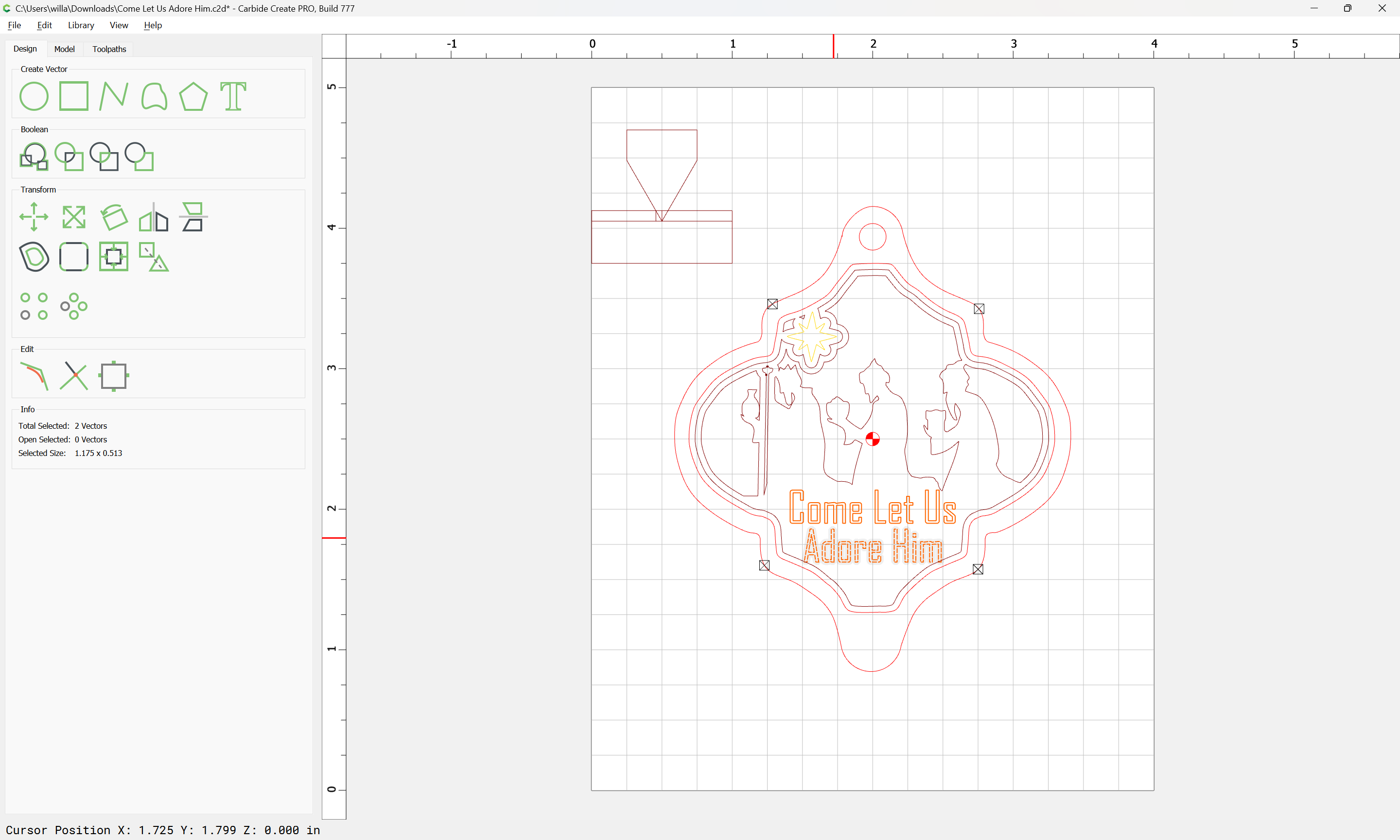
It looks like using the 2D Contours, the simulation looks like it will do exactly what I want.