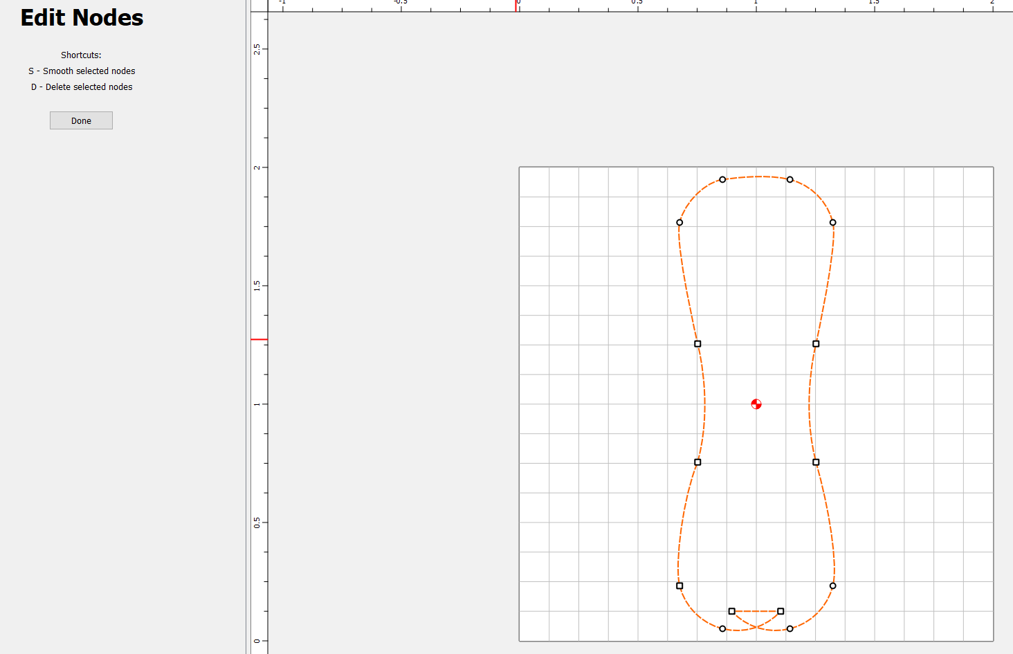
WHY??? Why doesn’t this curve look like the one on the top?
I think this is question for super @WillAdams , but I’m putting it out here as a general question. (BTW: I can fix the curve easily, I’m just wondering why it doesn’t behave like the top of the bone).
EDIT: Interestingly, if you start with the nodes on the bottom first, and then do the ones on the top, the top becomes the issue!
Is arguably something which should be disallowed — putting that in as a bug report now.
For oddities of placement, there seems to be some difference in how the nodes at the beginning/end of a toolpath are handled — we’ll have to see what the devs think of it.
Are you sure? Shouldn’t you be able to relieve a corner using the same tool you cut the slot with?
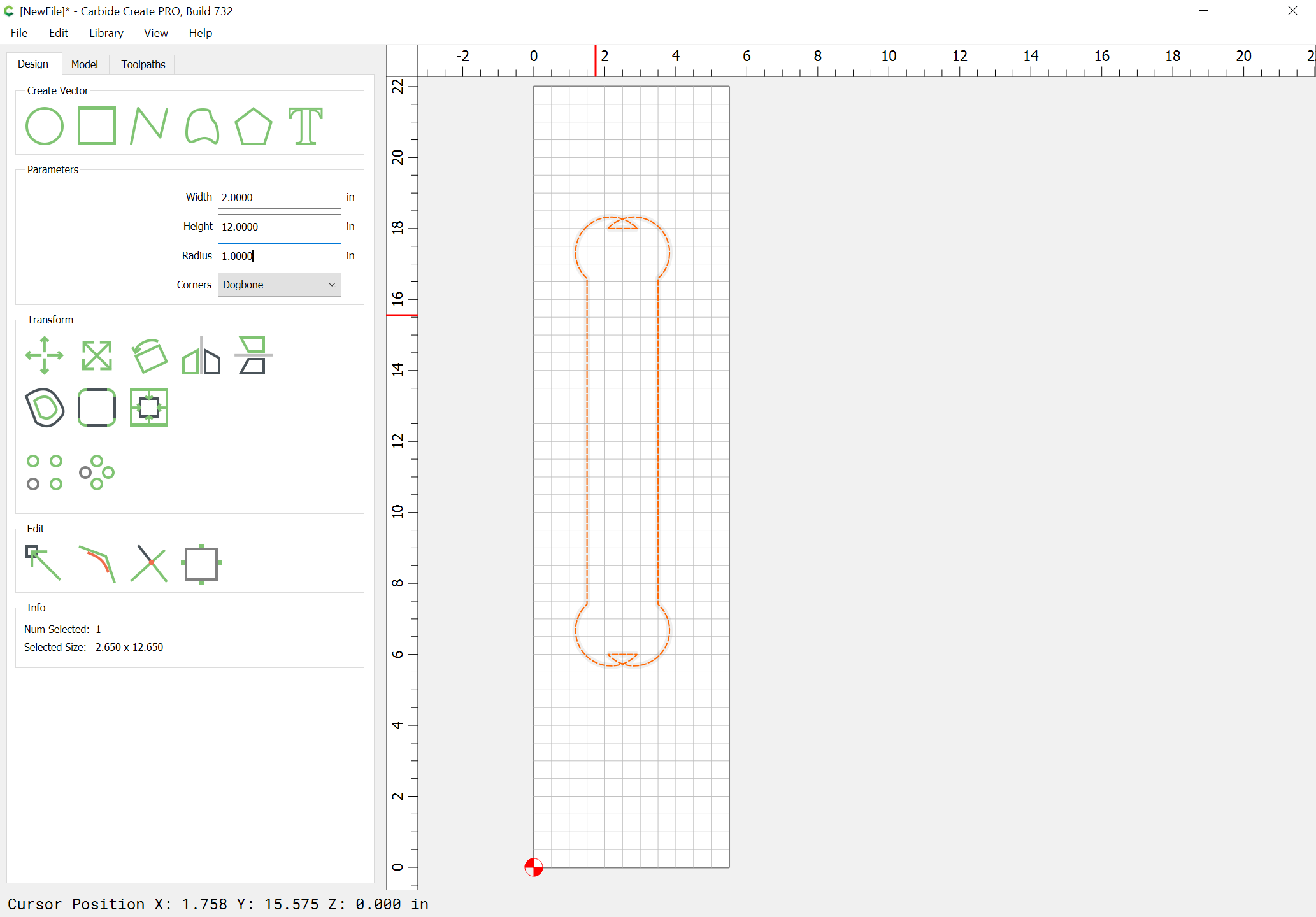
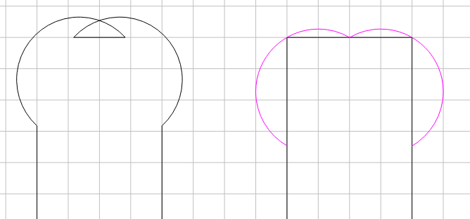
A 1" R dogbone on a 2" wide rectangle should look like…
This would require a different algorithm when the radius of the dogbone is more than half the rectangles width (or length, whichever is smaller).
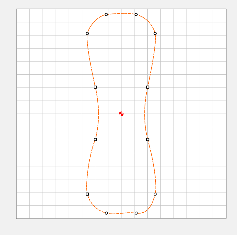
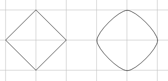
Edit Nodes surely does some weird things. For example, if I make the following polyline, then edit all the nodes to be smooth, I would expect a proper 3rd degree B-Curve through those points. i.e. a circle
Yet, the tangent vectors are all too short.
The object of the dogbone is to make room for a another piece with square corners, right?
My example is the minimum condition which still preserves the rectangles boundary, albiet just a single point on the ends, and allows a squared off shape to fit.
A circle is the “smoothest” curve that passes through those 4 points. If I create a B-Spline curve in NX through those 4 points I get a spline that looks just like a circle. If I create with G0 continuity, it’s a diamond. If I change it to G1-tangent (or higher), it looks like a circle. Unless I change the tangent or magnitude.
Even the curve tool is quirky, and I usually end up editing the tangents & magnitude after creating it.
It’s almost like it’s using a fixed value for magnitude, rather than adjusting for the distance between the points.