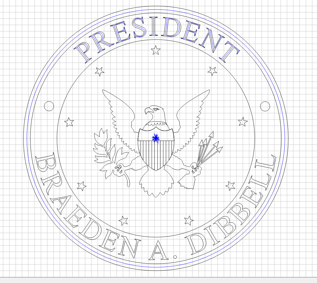
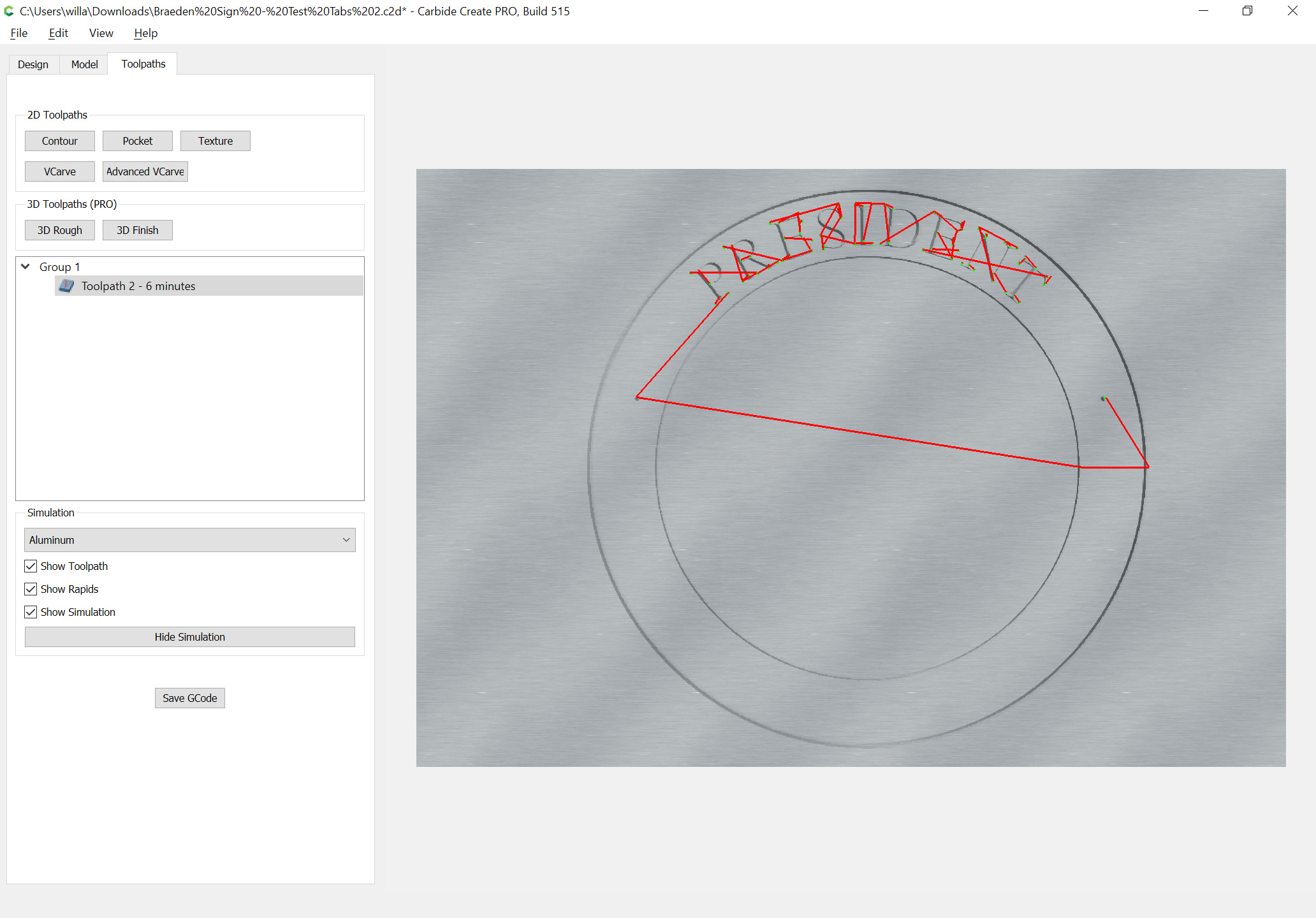
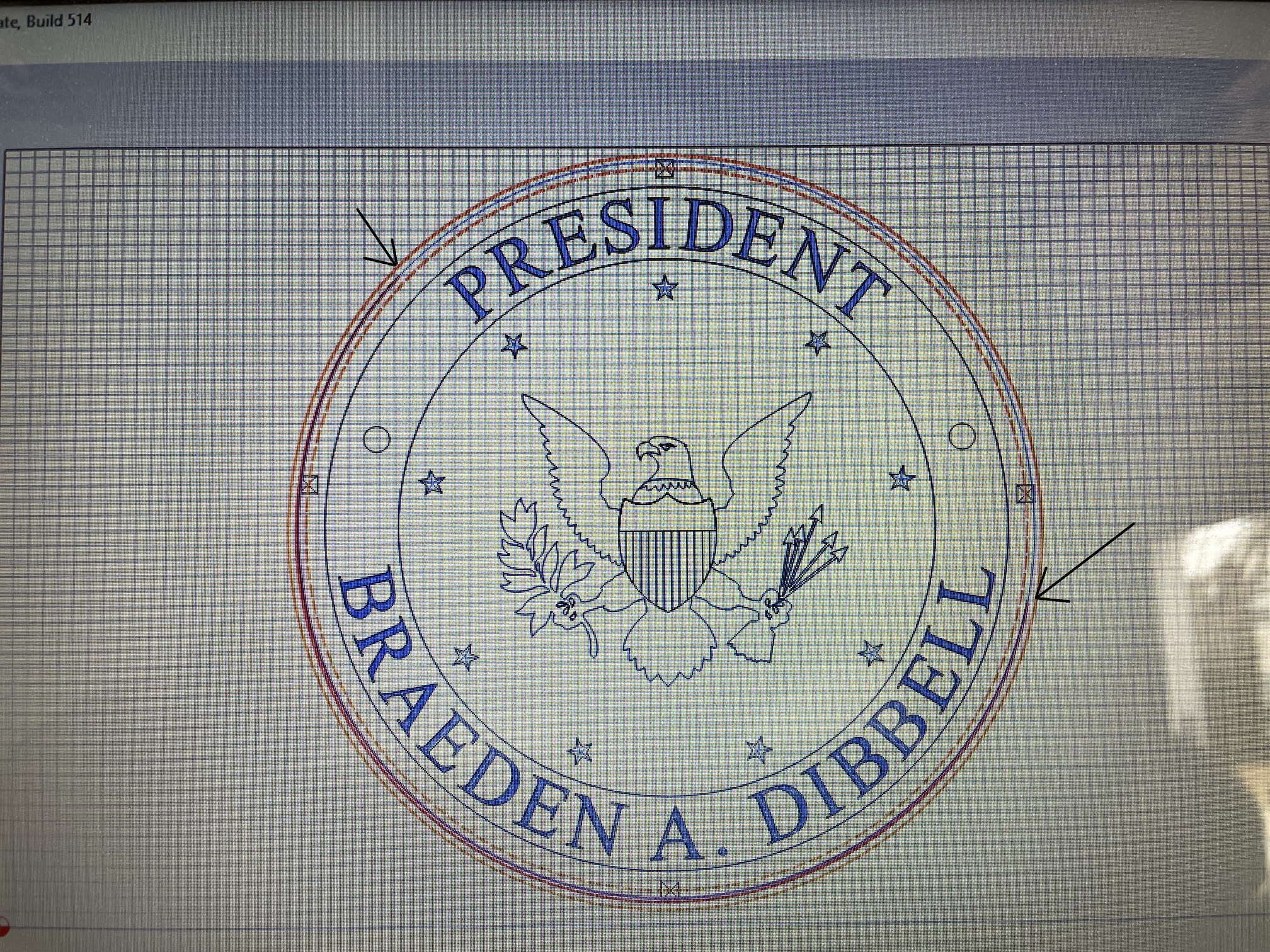
Anyone know what this is, or how to remove it?
Making a sign for a 9 yr old for their birthday.
Check and see if you have an extra vector hiding under one of the circular paths you selected for the vcarve. I have had similar issues when I have imported svgs that have vectors doubled up.
I only selected what you see. I’ve tried selecting just a circle or star and nothing else and the center thing still shows up.
Post the file and we’ll work this out with you.
Braeden Sign - Test Tabs 2.c2d (2.1 MB)
Thanks @WillAdams !
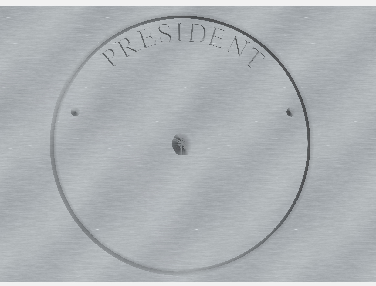
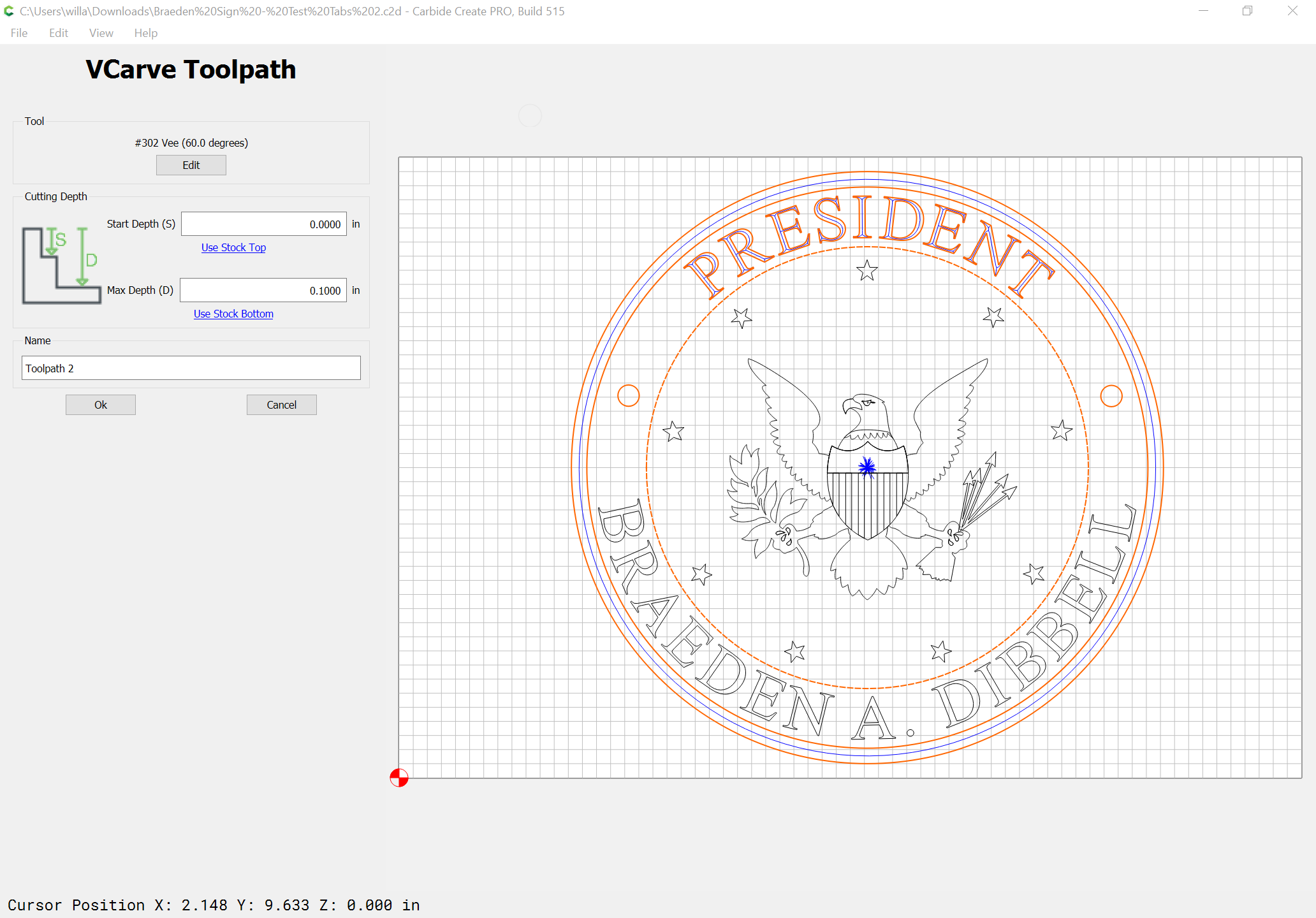
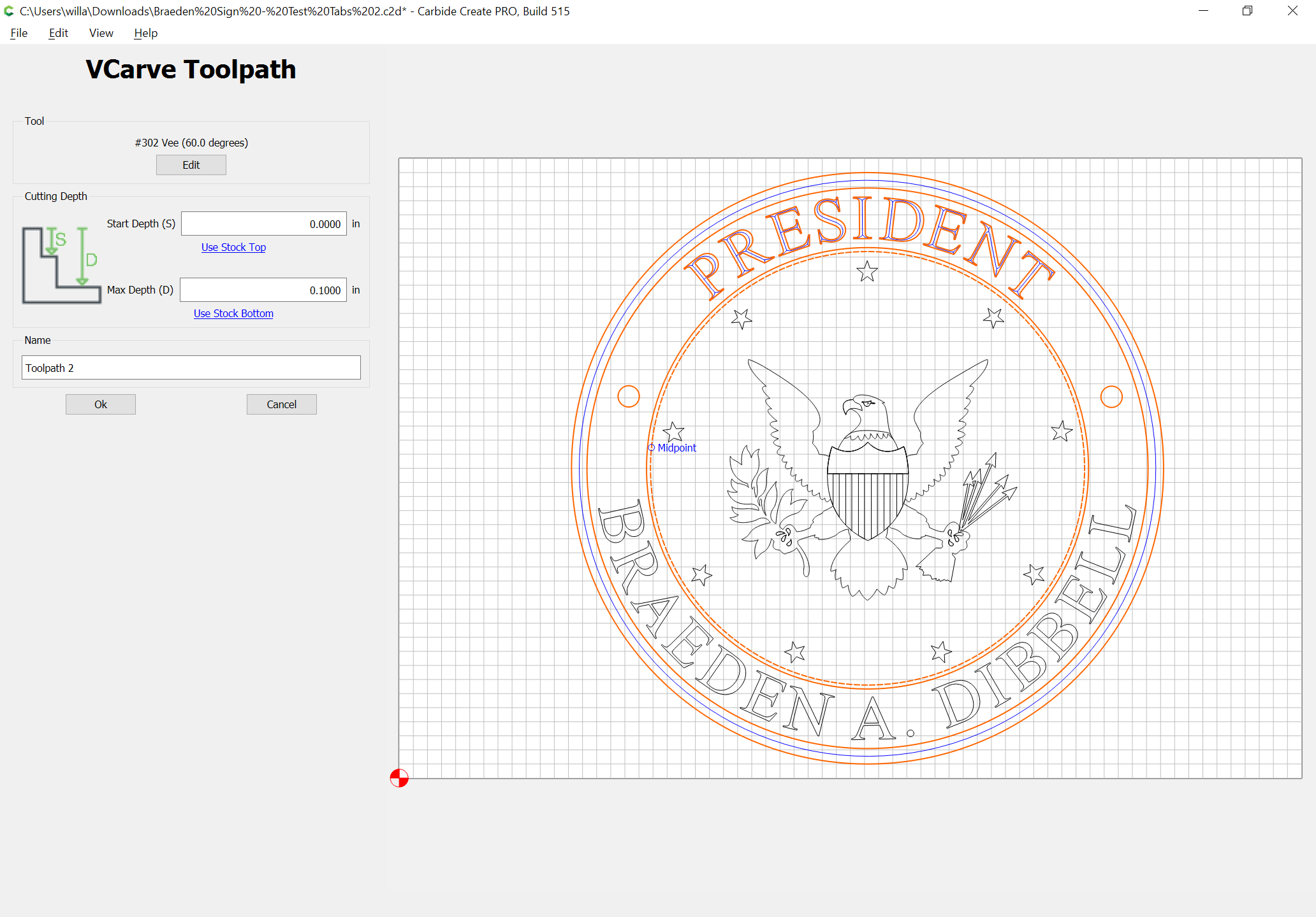
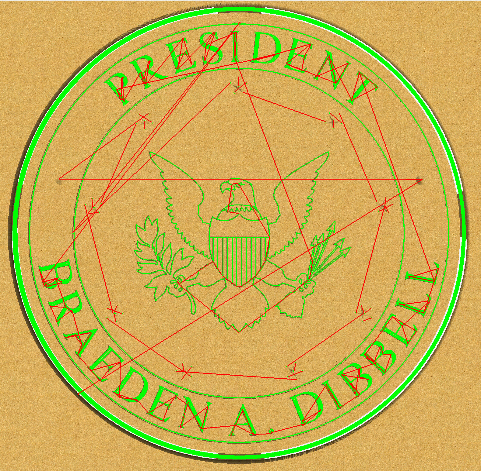
The problem is you have the inner circle selected as part of the V carving:
Remove it from the toolpath:
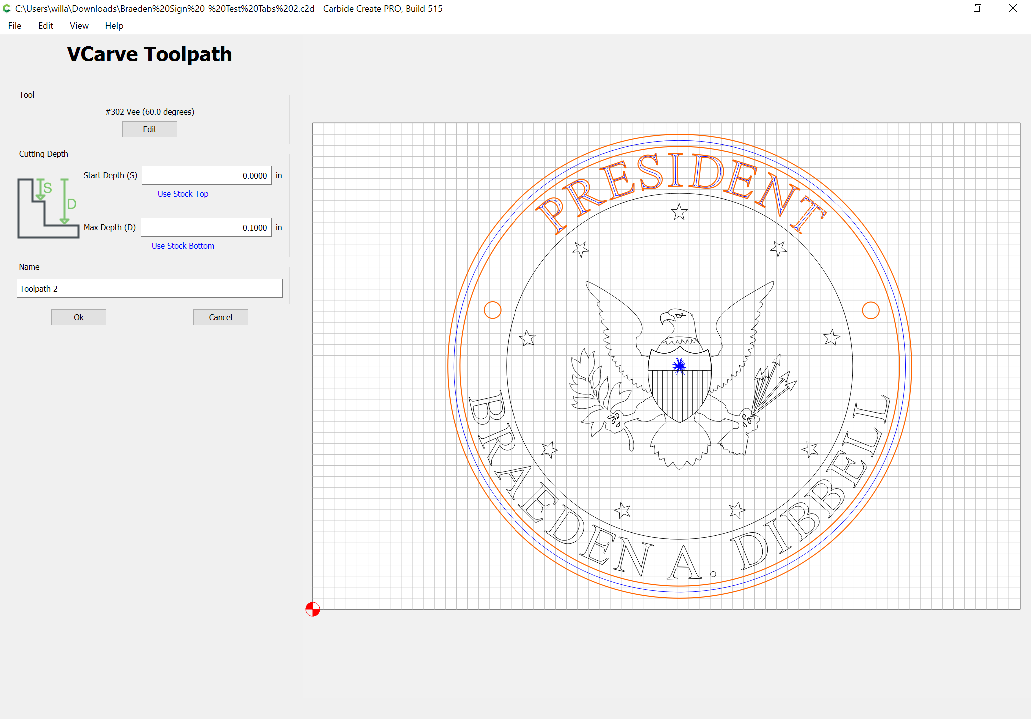
and the result will be more as is expected:
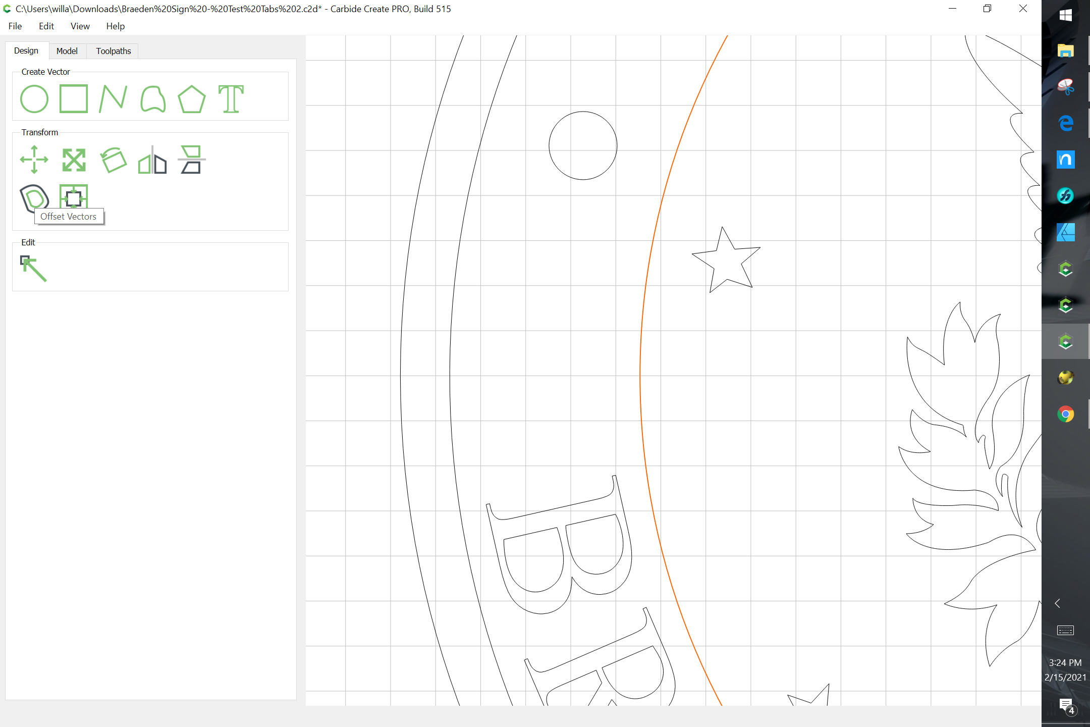
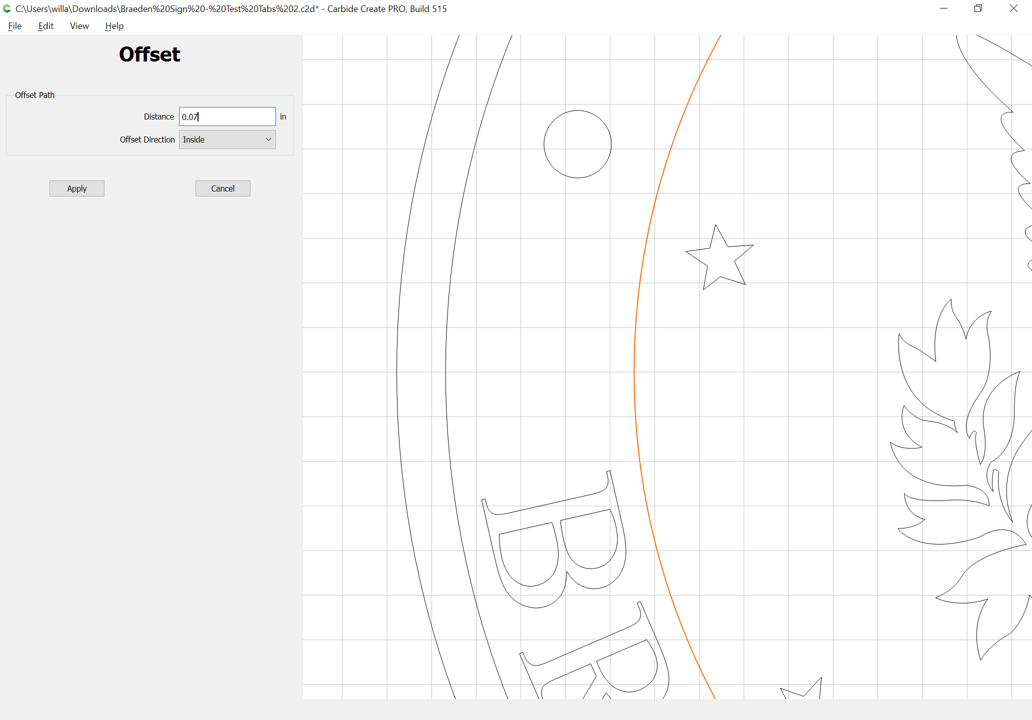
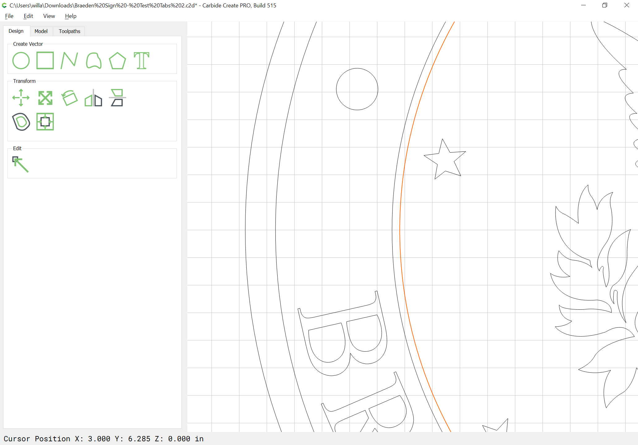
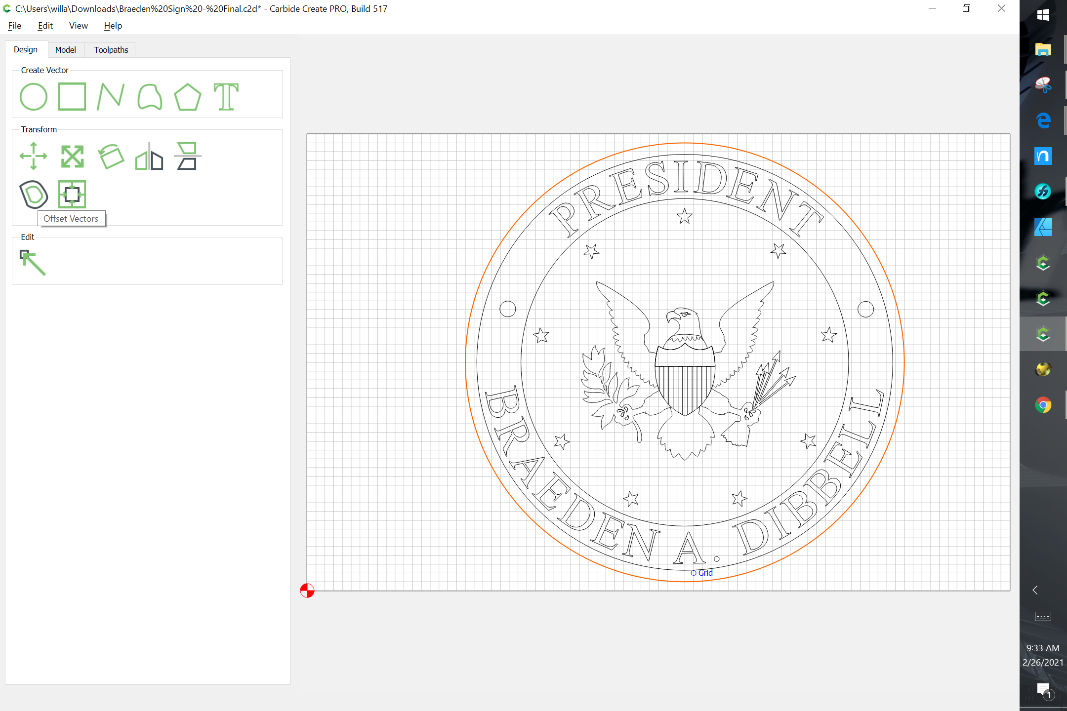
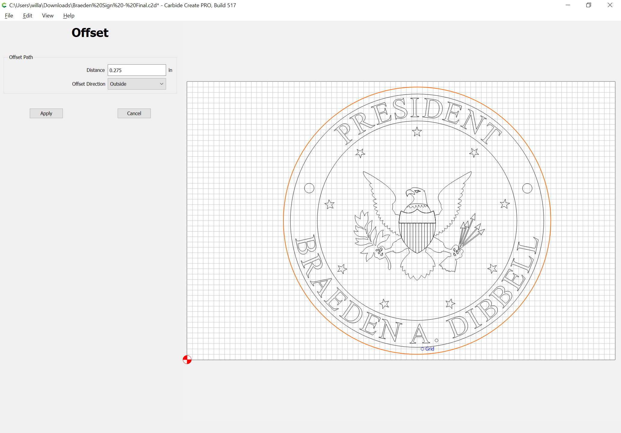
Alternately, inset the circle:
Apply
Uggg!! I feel so stupid - thank you!
No, don’t feel stupid. These are the exact kind of a-ha! moments I like to read about on the forum. Much faster than my puzzling over my own errors. Reminds me of job interview question “why is this cutting unexpectedly?” Answer: because the VCarving the wrong selections can make weird artifacts. Lesson learned (at least for today.)
Learn from the mistakes of others; you won’t live long enough to make them all yourself!
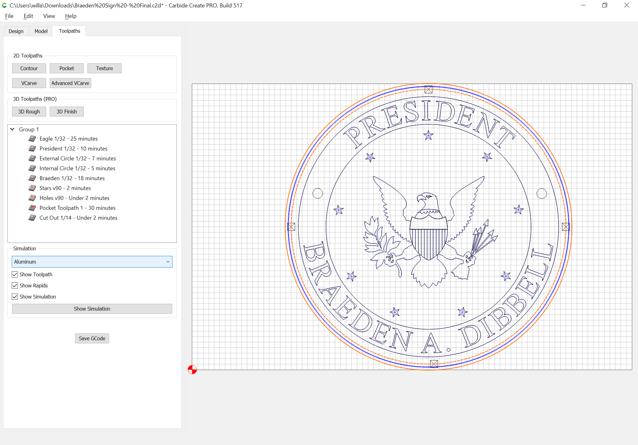
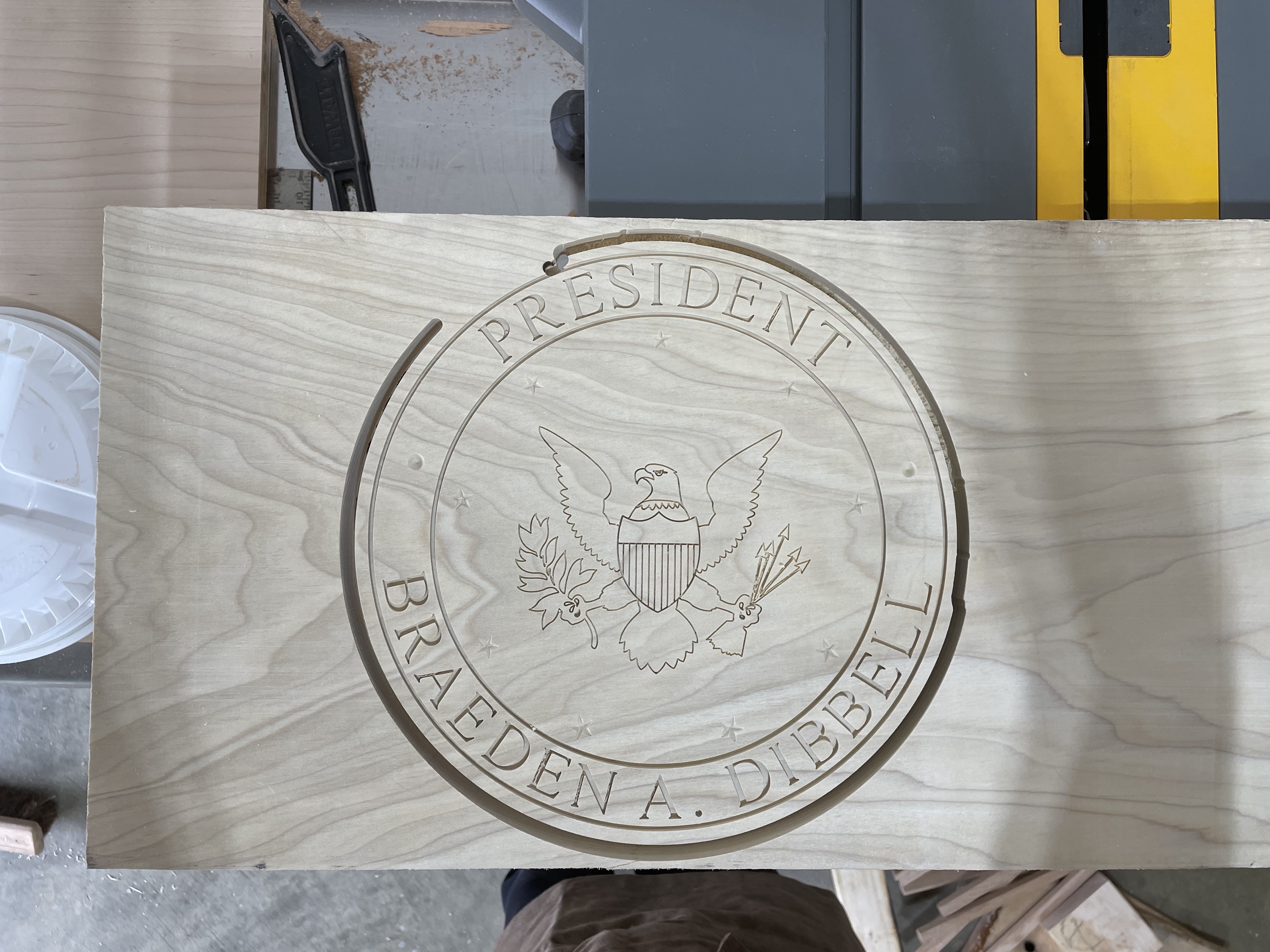
Ok, I probably did this with too many toolpaths, but the end result was what I wanted, so I guess it works.
If you have a moment, @WillAdams , can you explain tabs? I want to cut this entire thing out so it’s a round logo. I don’t mind cutting off some tabs later to make the work holding easier, but I’m not figuring this out. These tabs look microscopic so I gave up and removed them.
Braeden Sign - Final.c2d (2.2 MB)
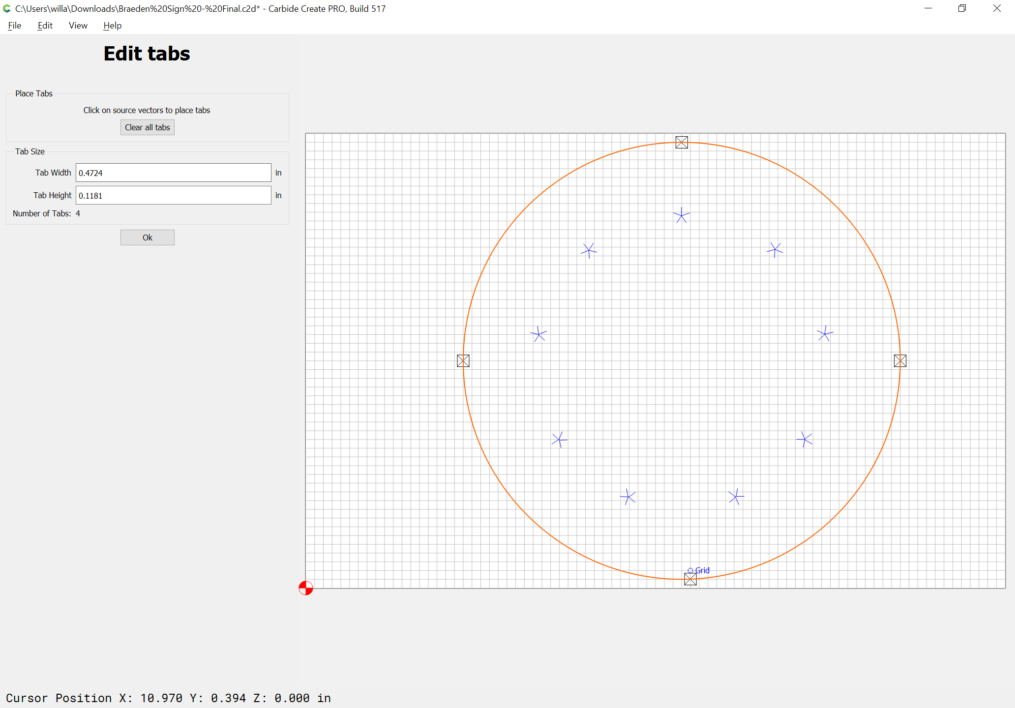
Tabs should be explained in:
https://docs.carbide3d.com/assembly/carbidecreate/video-tutorials/#holding-tabs
It’s simply a matter of assigning their width and height to match the holding necessary:
and of course, they only make sense for cuts which go all the way through:
If you want them larger, just increase the size:
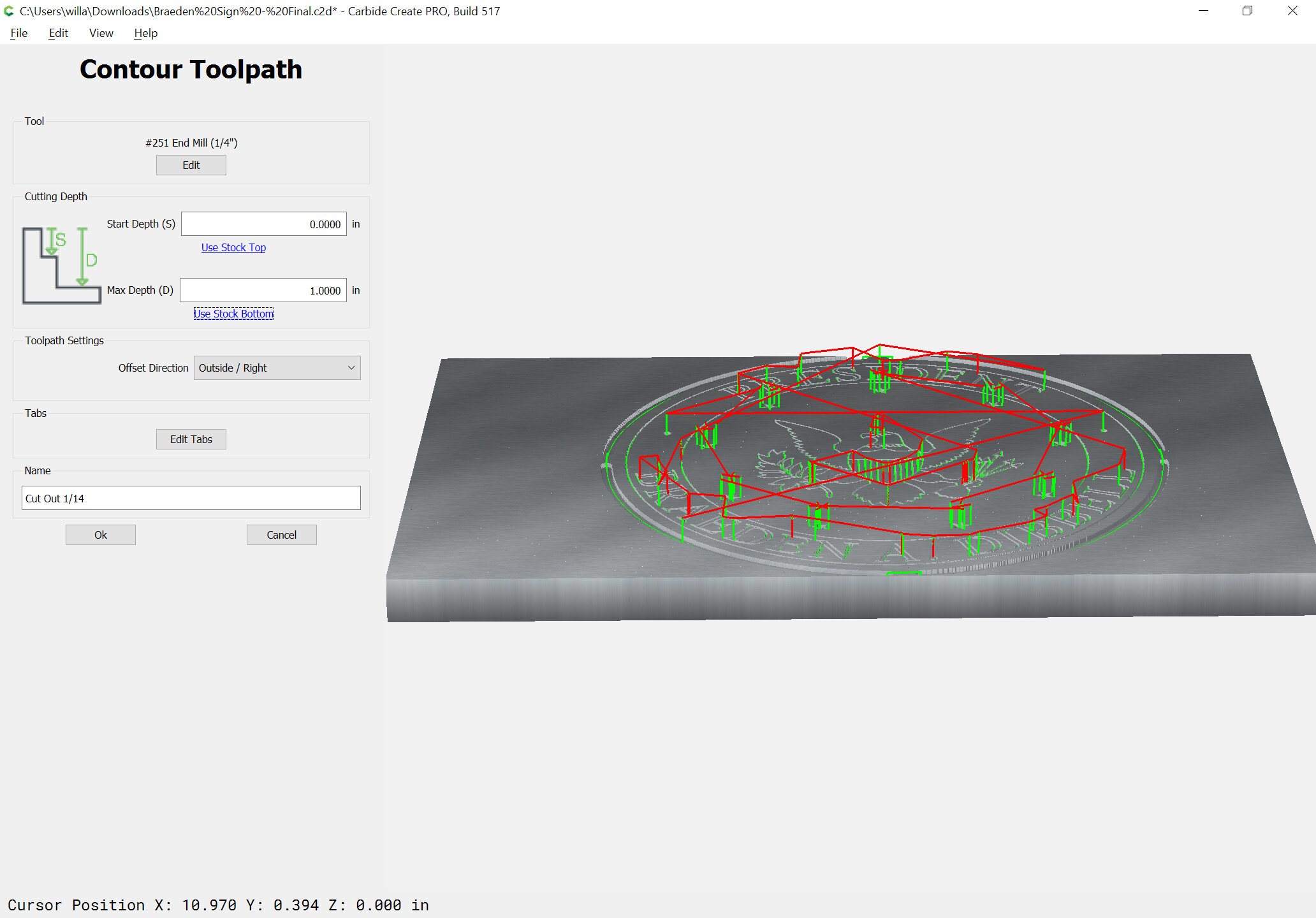
Note that it’s best to not cut a slot just as narrow as the endmill — that results in 100% tooling engagement, so add offset geometry ~10% wider than the endmill you are using;
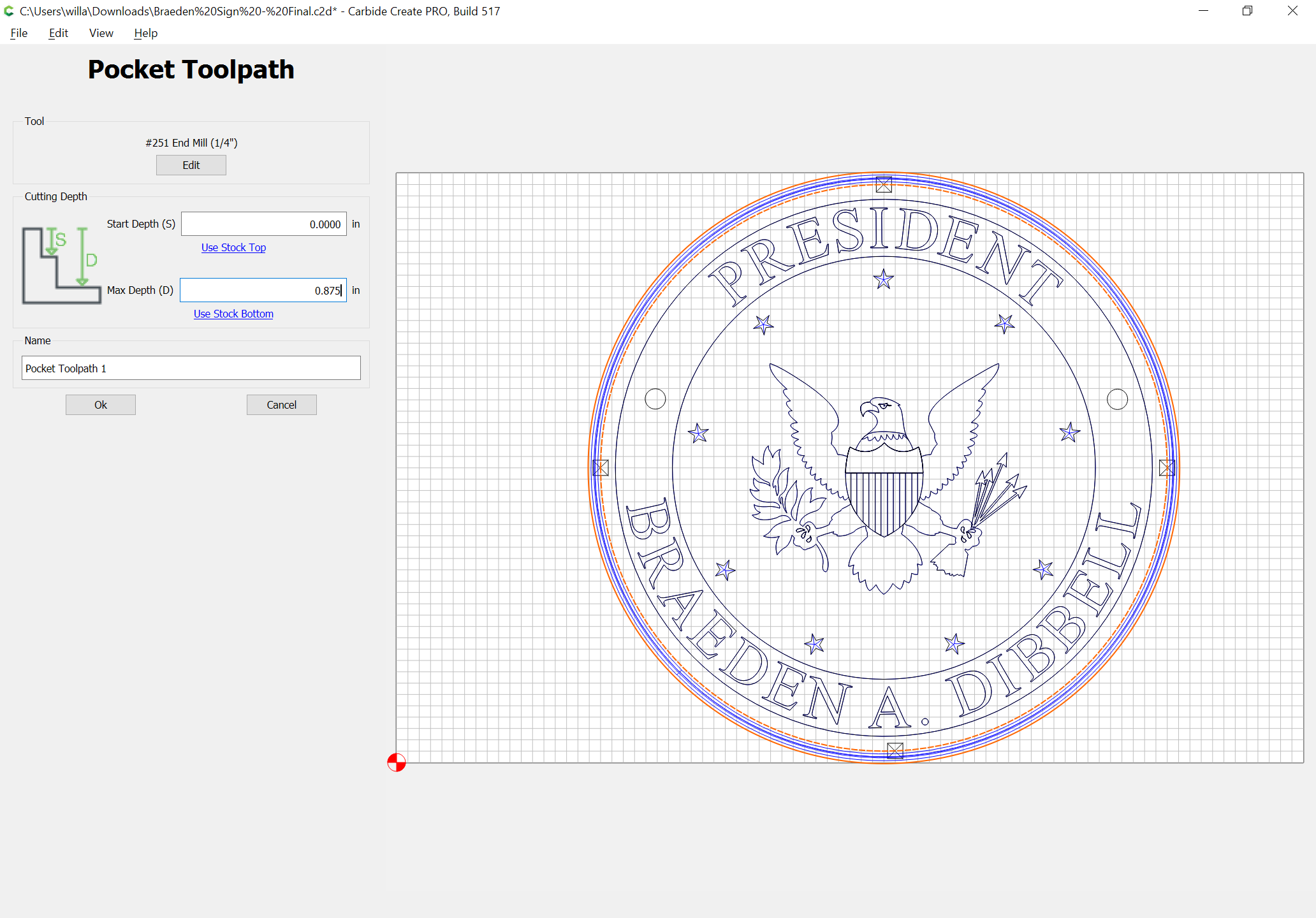
Cut as a pocket down to tab depth:
Move the pocket above the profile cut:
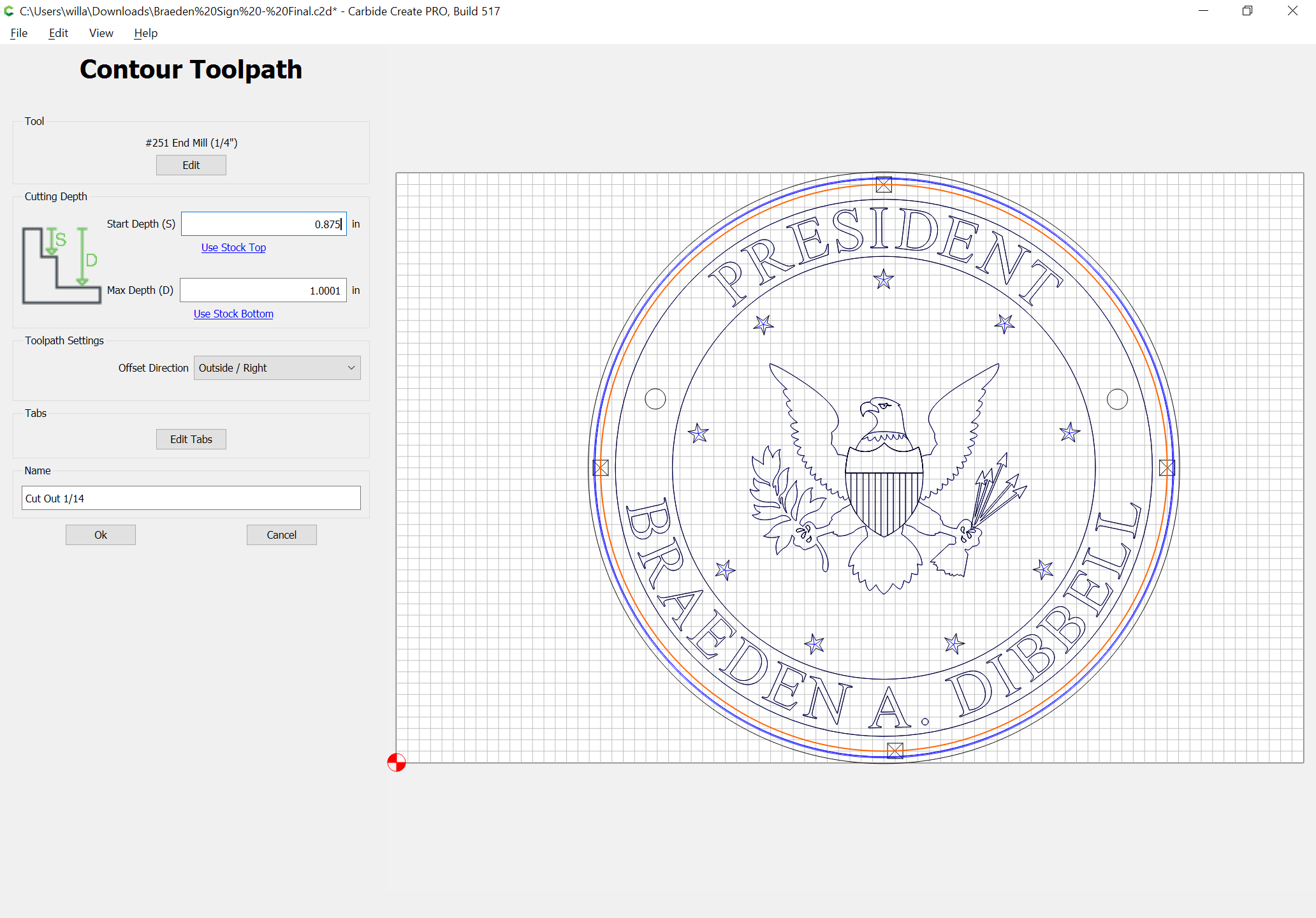
edit the profile cut to start at the bottom of the pocket:
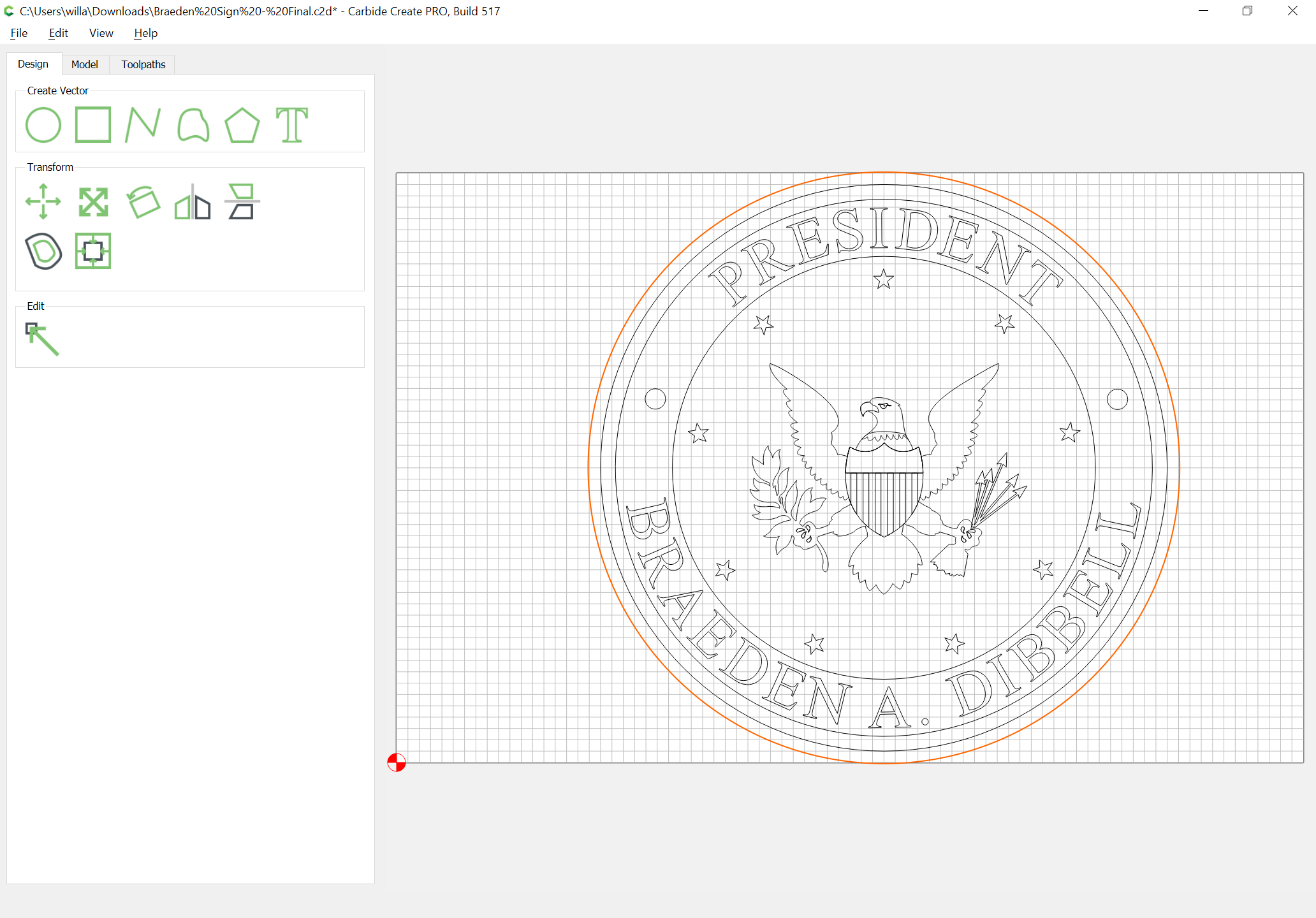
to arrive at:
For an optional improvement, increase the out profile offset distance and add a second offset of the original geometry to create a roughing clearance:
THANK YOU!!! That is exactly what I couldn’t figure out (tab size) and didn’t know about the offset/roughing.
@WillAdams I really appreciate the time you took!
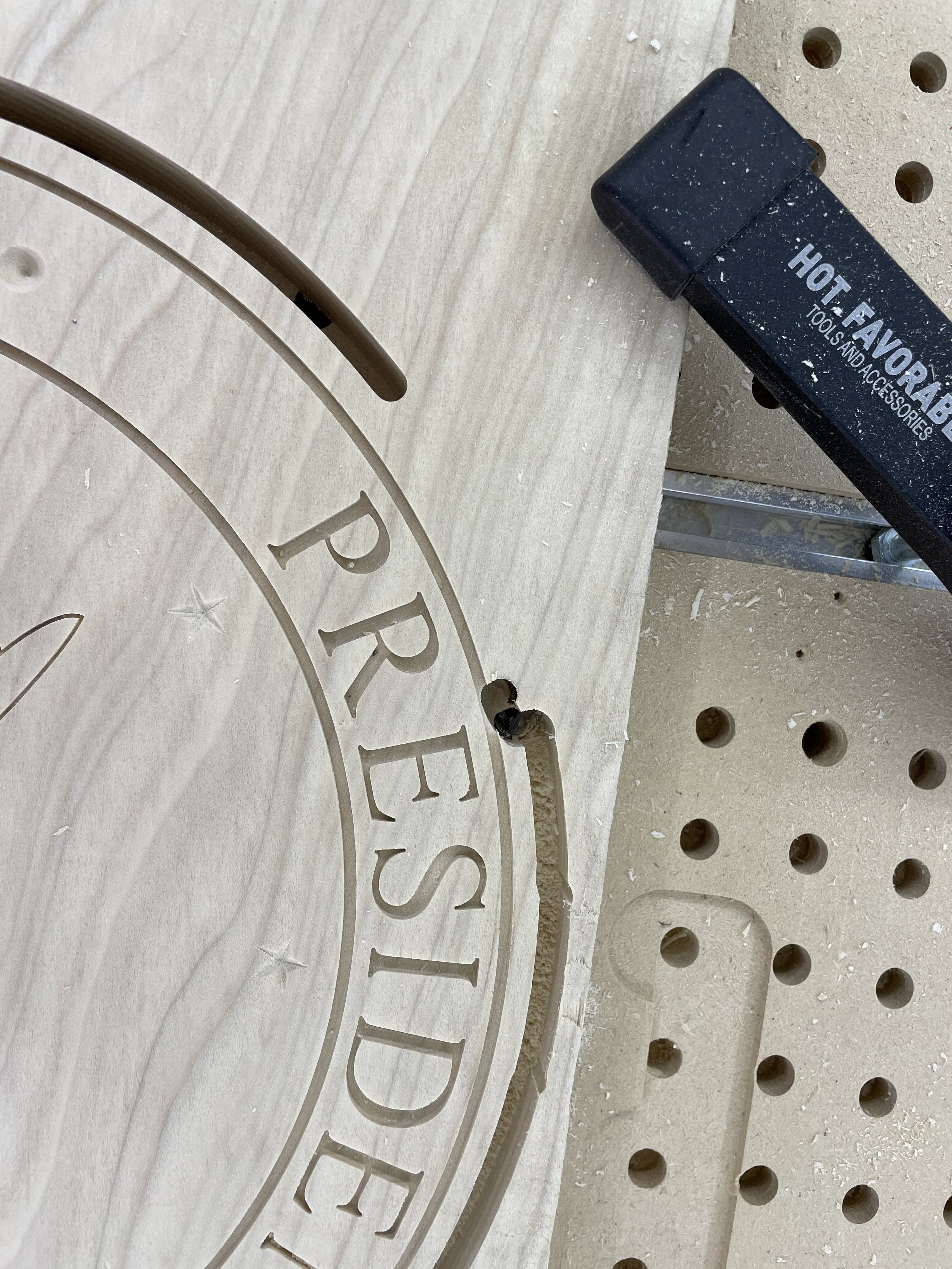
Crap, I totally hosed my cut! At least is was a test cut, right?
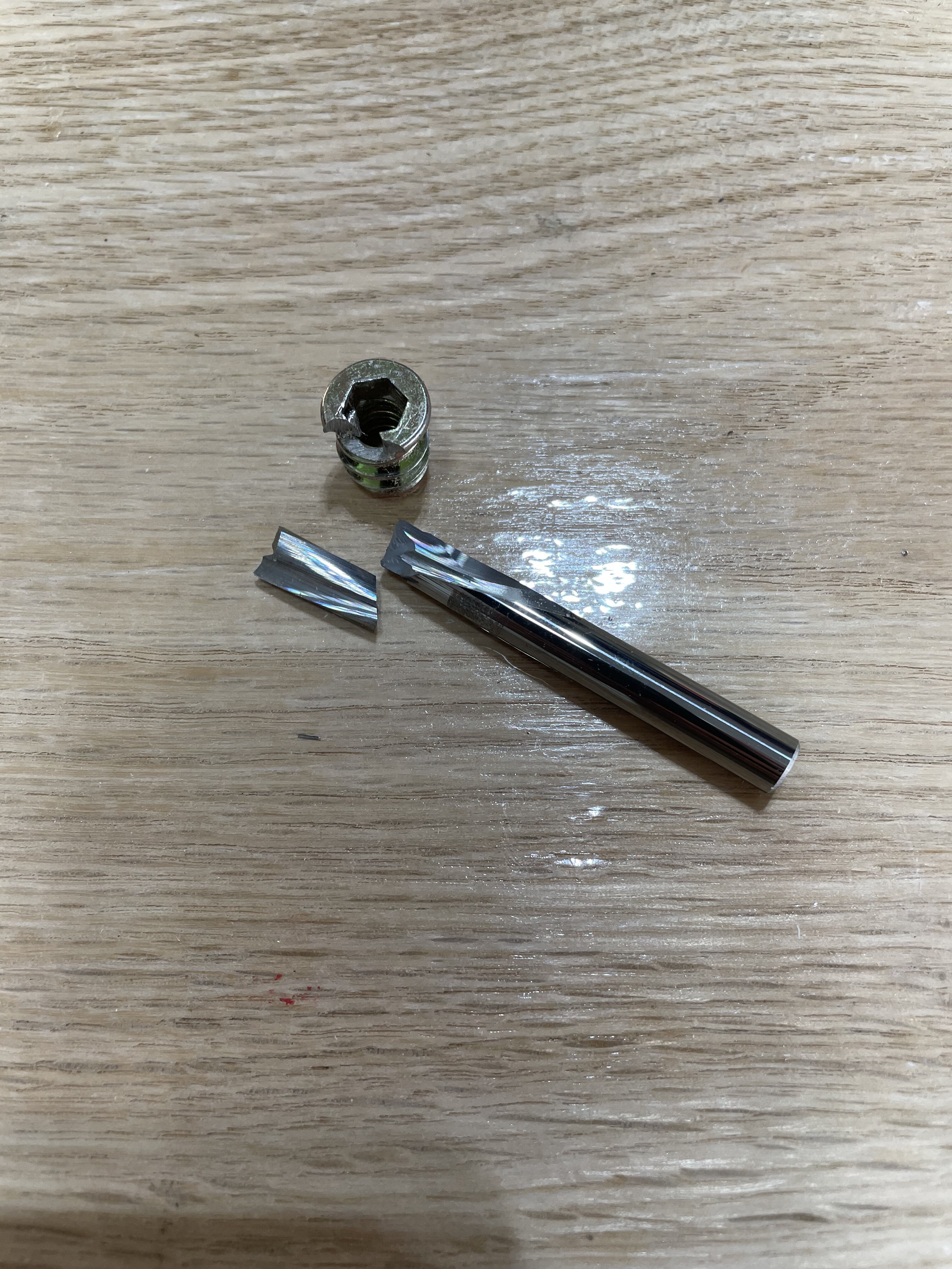
What happened was I forgot to change the depth of the offset and profile cuts. After I created the file I ended up planing the wood slightly and forgot to change them. Cut too deep and hit a threaded insert. My only #251. I’m hoping I can just use a #201 going forward for the next cut.
Measure twice…
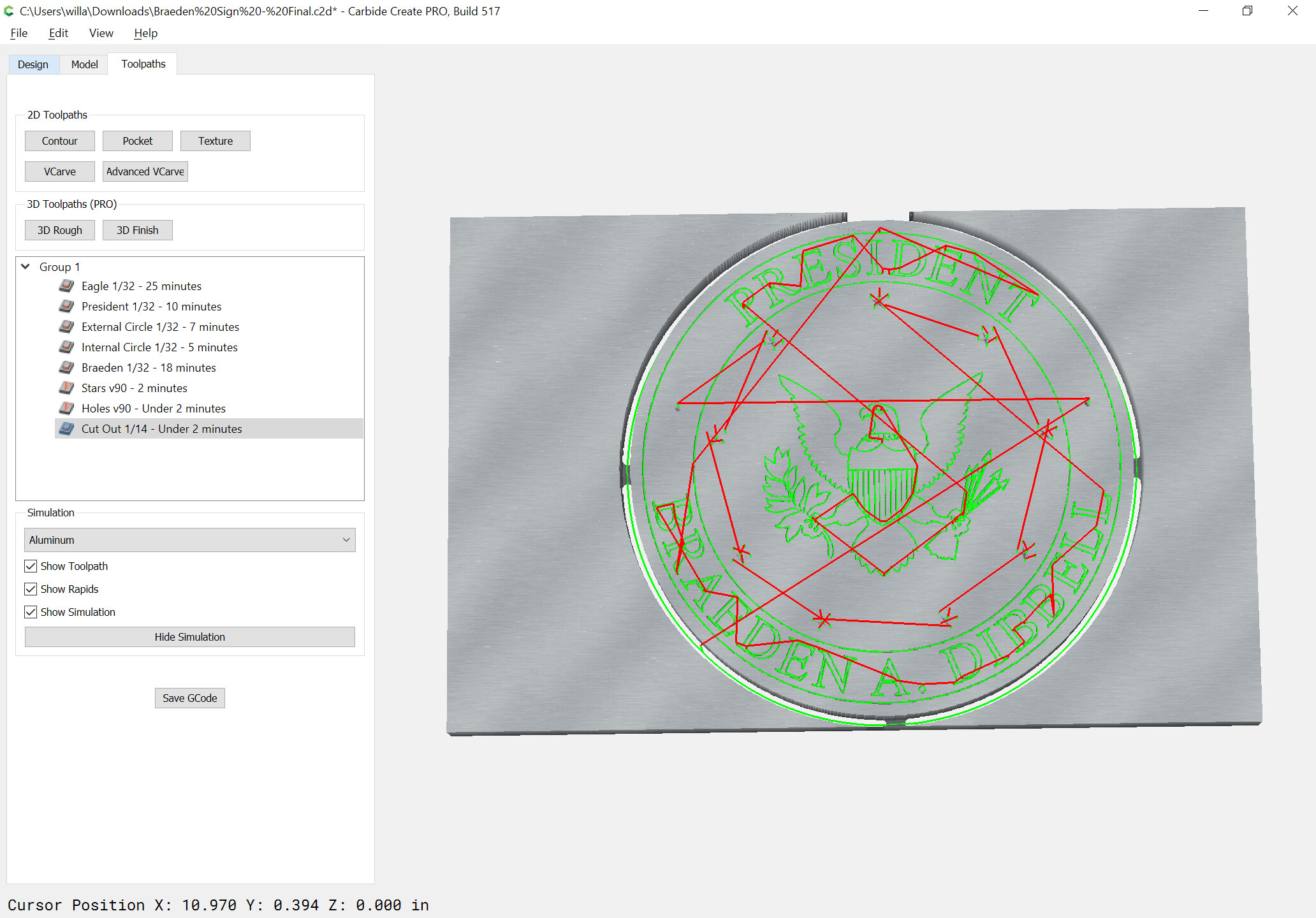
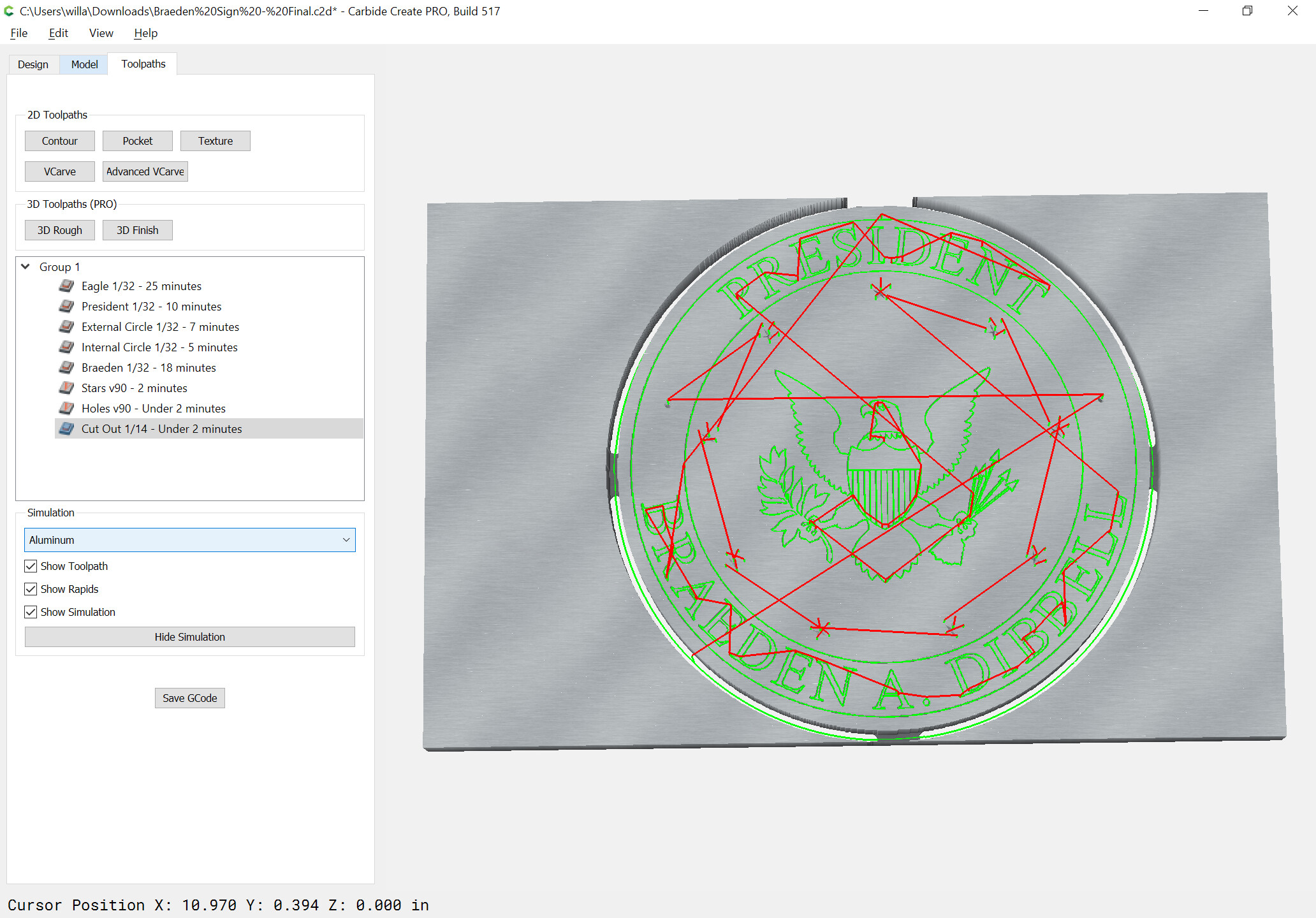
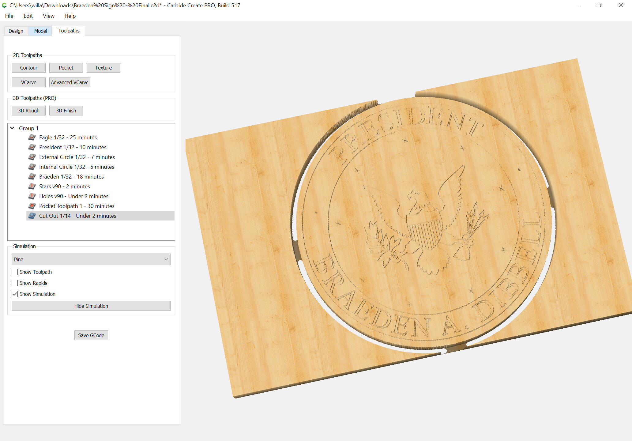
However, @WillAdams , any idea why the offset cut didn’t go all the way around? I didn’t notice until it actually cut, but you can see it in CC.
Could the offset original path have been moved?
Not sure — post the file?
Braeden Sign - Test Cut.c2d (2.4 MB)
Attached - thanks!
Hi Les, Les here. The two outer circles are not on the same centers. This is causing the pocket operation to have enlarged lower half. Try recentering those objects and you’ll be good to go.
So, select the outer circle and inner circle and align centers?
Yes, I selected the outer circle then inner circle so it was the reference, and aligned their centers.
Perfect, thanks Les!
I did that in CC and it shows it goes all the way around. No idea how that happened! I’ll look out for things like that going forward. Always a learning experience with this stuff!
Slightly OT, but if you pocket a circle that’s 10% (or so) wider than the cutter how does that help? The first cut still has to be a full cutter width wide slot.