Sunday 30 minutes or less challenge (or any day really)

So kids are busy in the fields somewhere on my land, wife is happy in sowing room - Que exit stage left for Dad to the workshop (old school Batman transition music)

Now i have had a big tidy up inspired by both John’s from NYCCNC and Grimshaw Knives podcast series "highly Recommend from both a technical and philosophical standpoint as well as workflow etc) Podcast series is called “the business of machining” on Spotify must be able to get it elsewhere.

Anyway back on topic, John Saunders said today in the podcast “learning needs to be real” long story short he is talking about prototyping or learning new techniques adds far more value when done for instance on a widget you are trying to sell rather than a circle.

One of the topics the two Johns were talking about today was tooling tray, (automated) that resonated with me, and i decided that i will adopt this Pallet approach, i.e. a pallet for each job or thing i do, this is achievable because i am a hobby / semi productioninst (if there is such a word ) i can afford to do this because costs are still relatively low

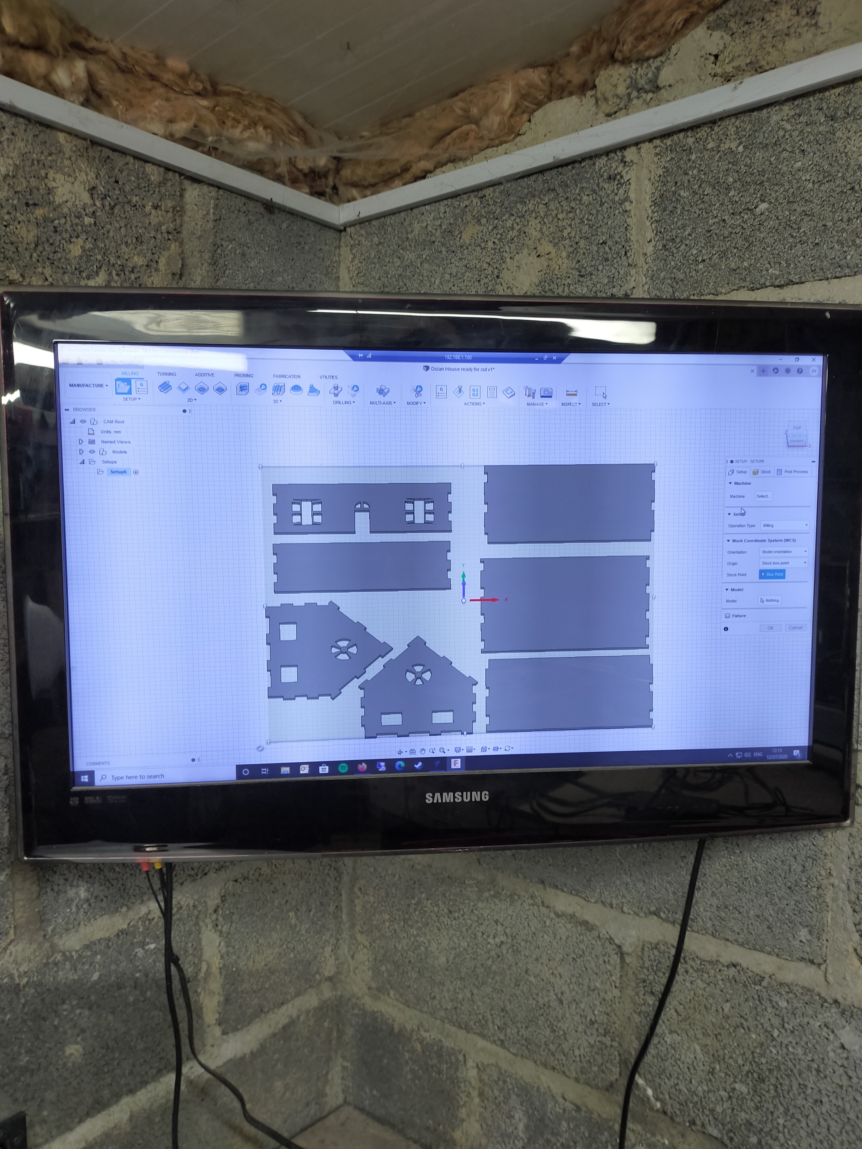
Inspired by this and wanting to have a bit of fun, i set myself 30 mins to design as many things as i can, that had to conform to the following:

  • Functional that i can use to increase / decrease my workflow
  • Use a toolpath or technique that i have not fully understood or delved into
  • Finish “thing” must be right first time - no revisions or tweaks
  • Total tooling and design time must not exceed 30 mins

I found this to be very refreshing and i have a little notepad full of things to follow up on.

I would welcome other peoples additions to this thread to see what you come up with, but be super strict 30 mins or less folks…

I did 4 things today 5 in total, but one failed the right first time measure.

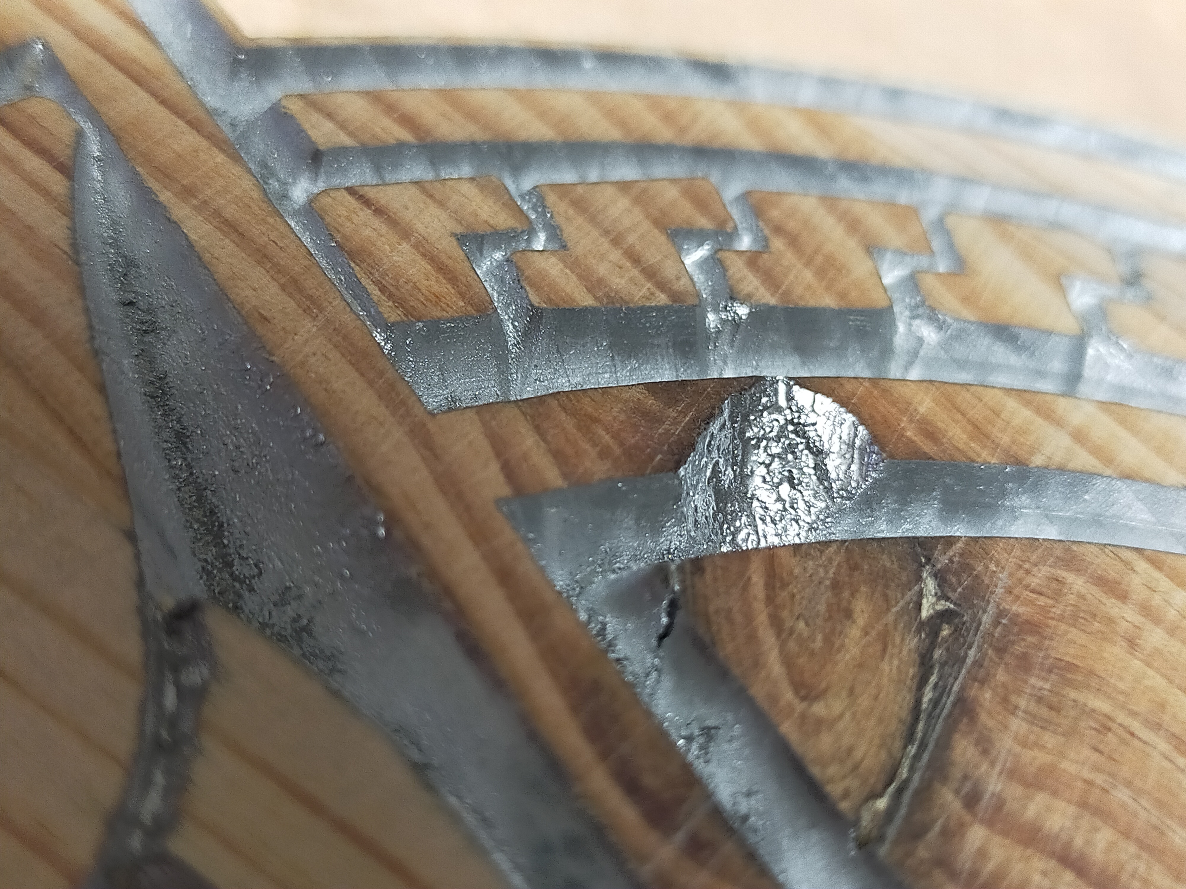
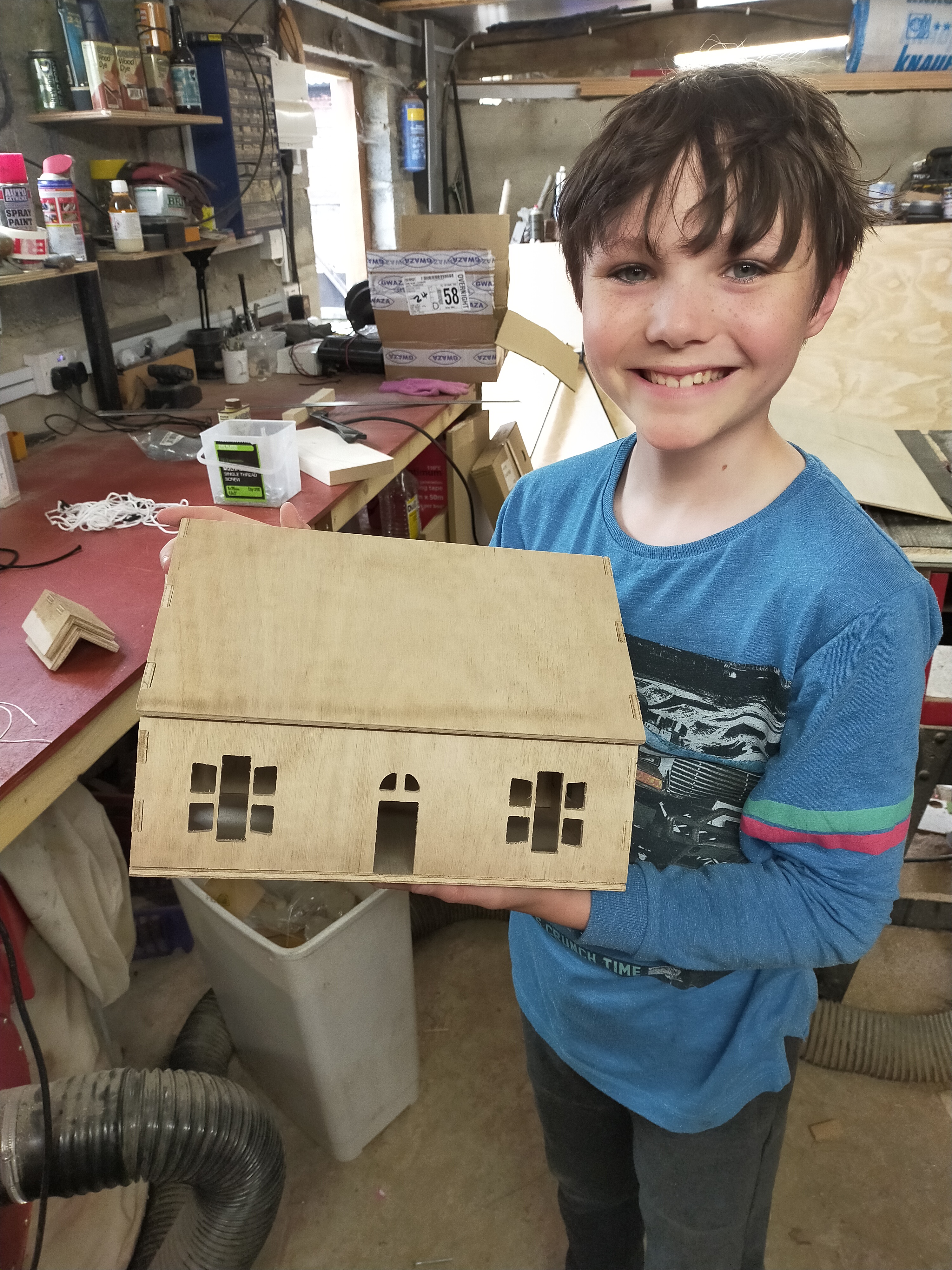
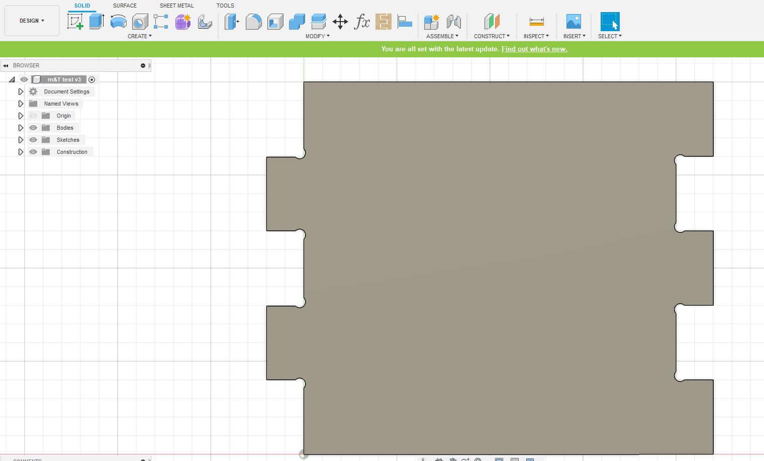
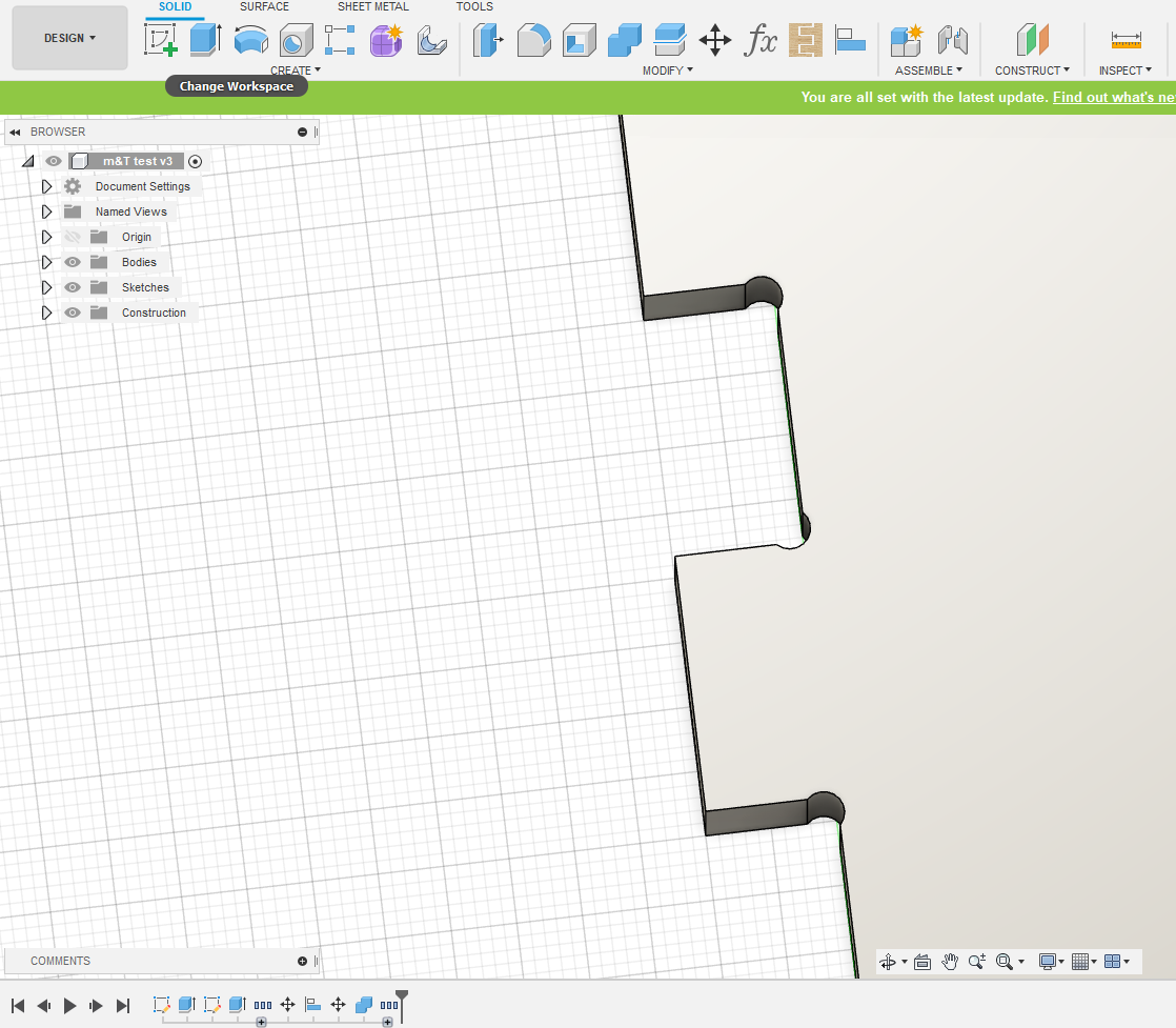
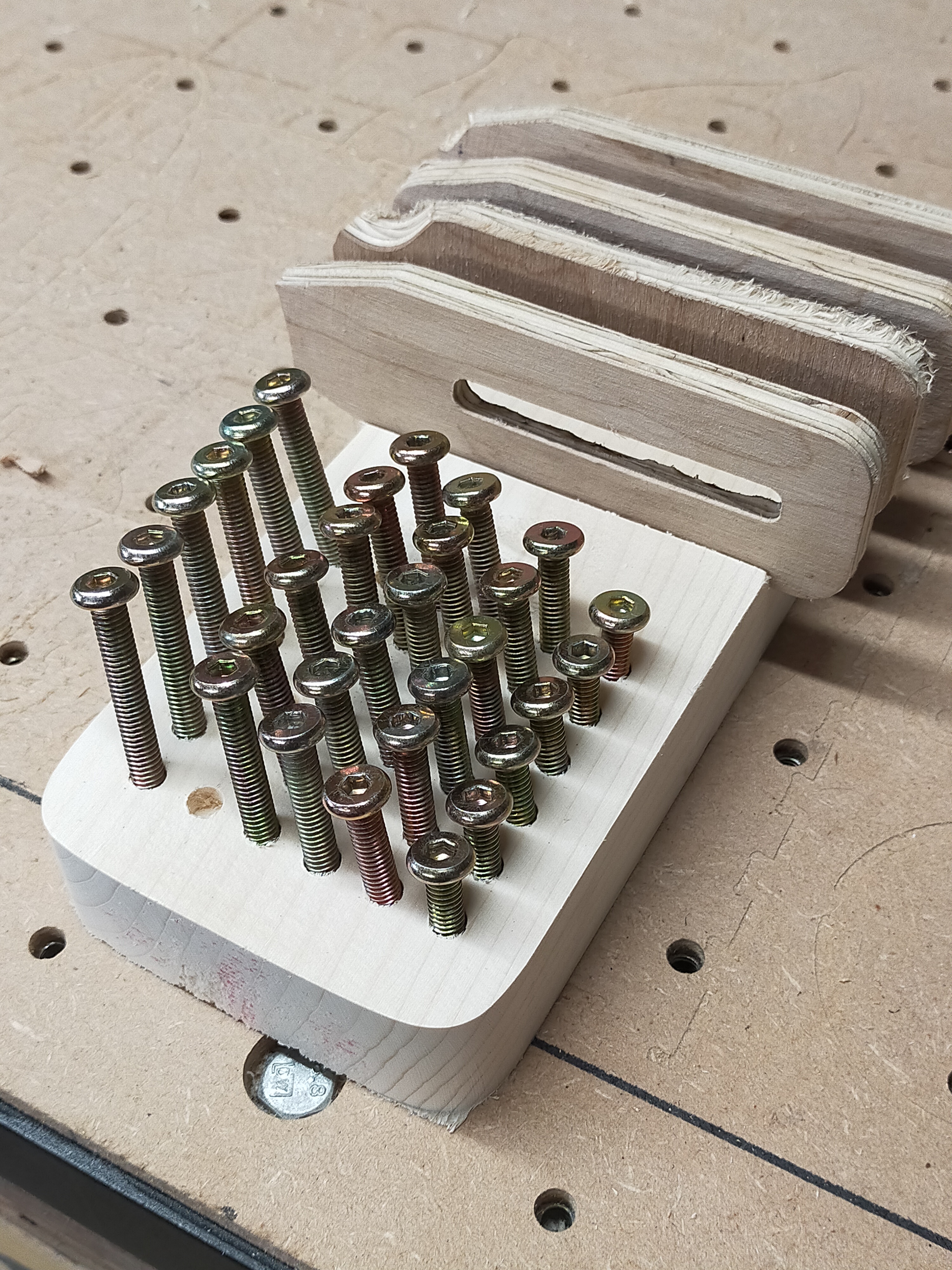
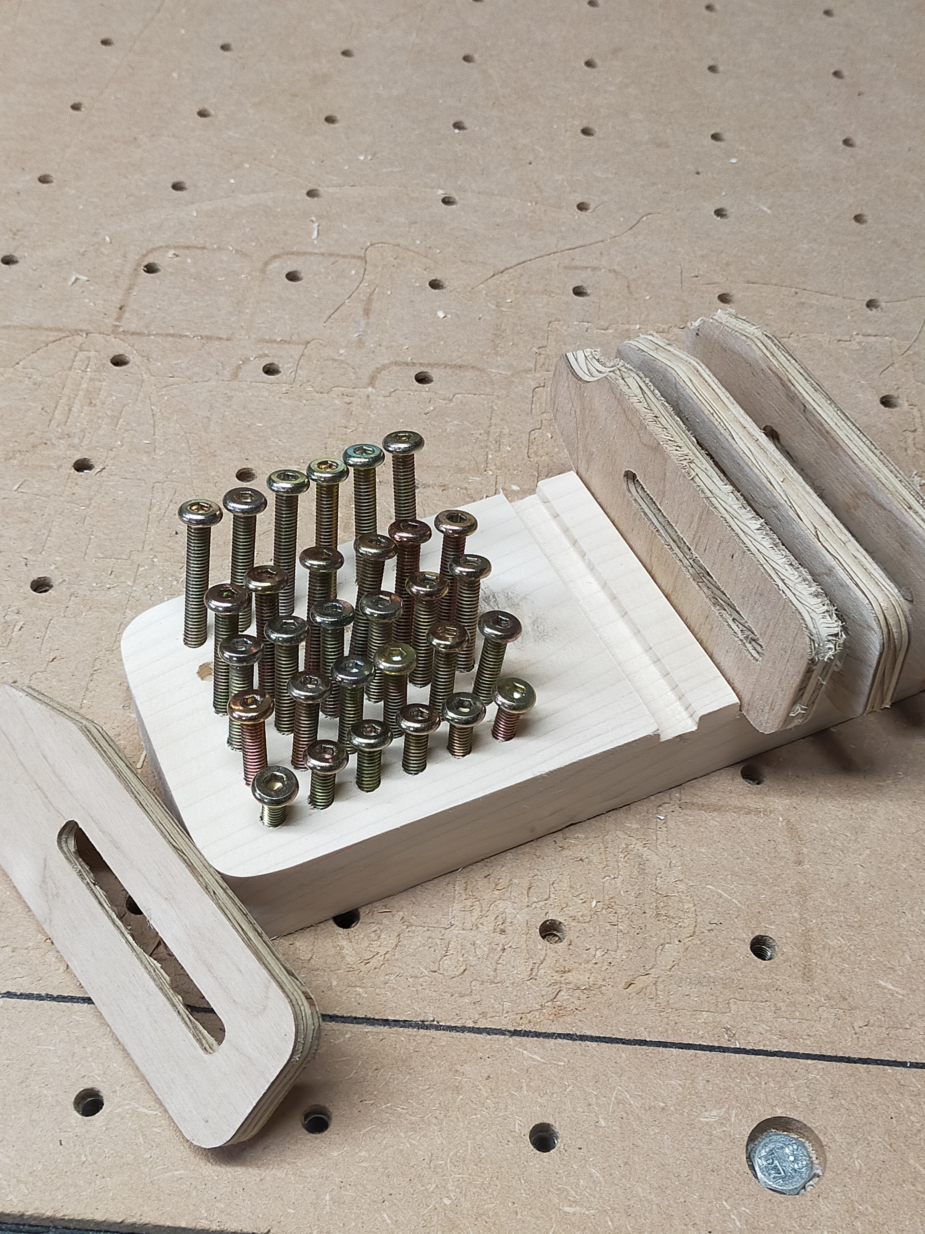
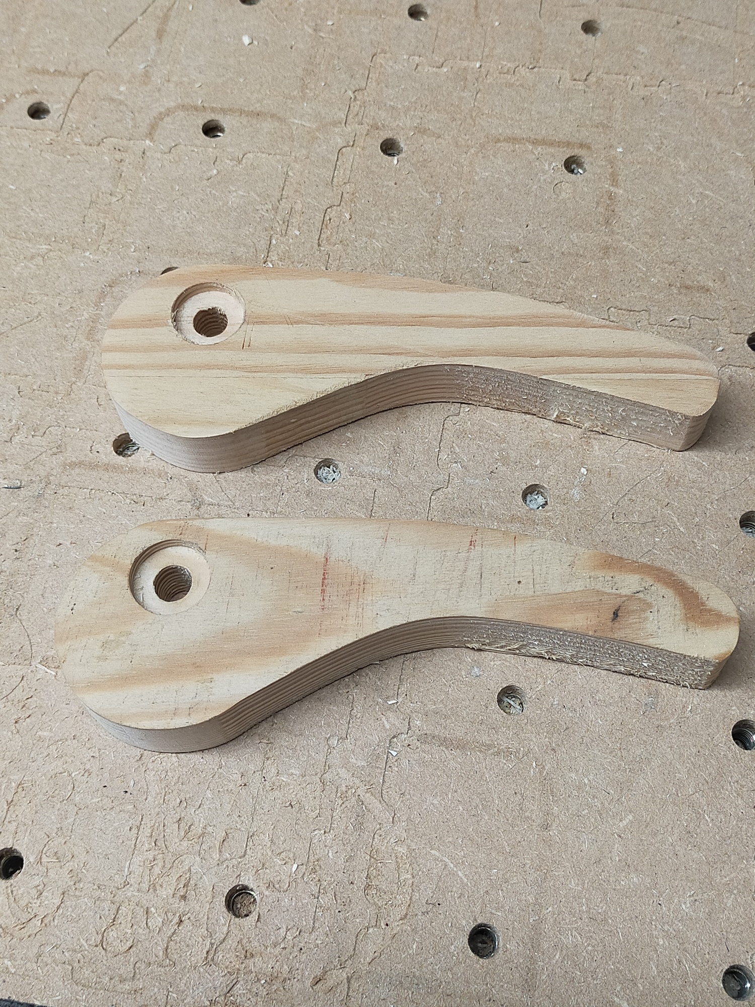
First - clamping pallets

Design concept - have a pallet that is setup for different clamp amounts, typically i use between 2 to 10 clamps to hold things down, and get frustrated that sometimes i cant find them quickly, either because i broke some and said “i will make some later” or the magic drawer has swallowed them!

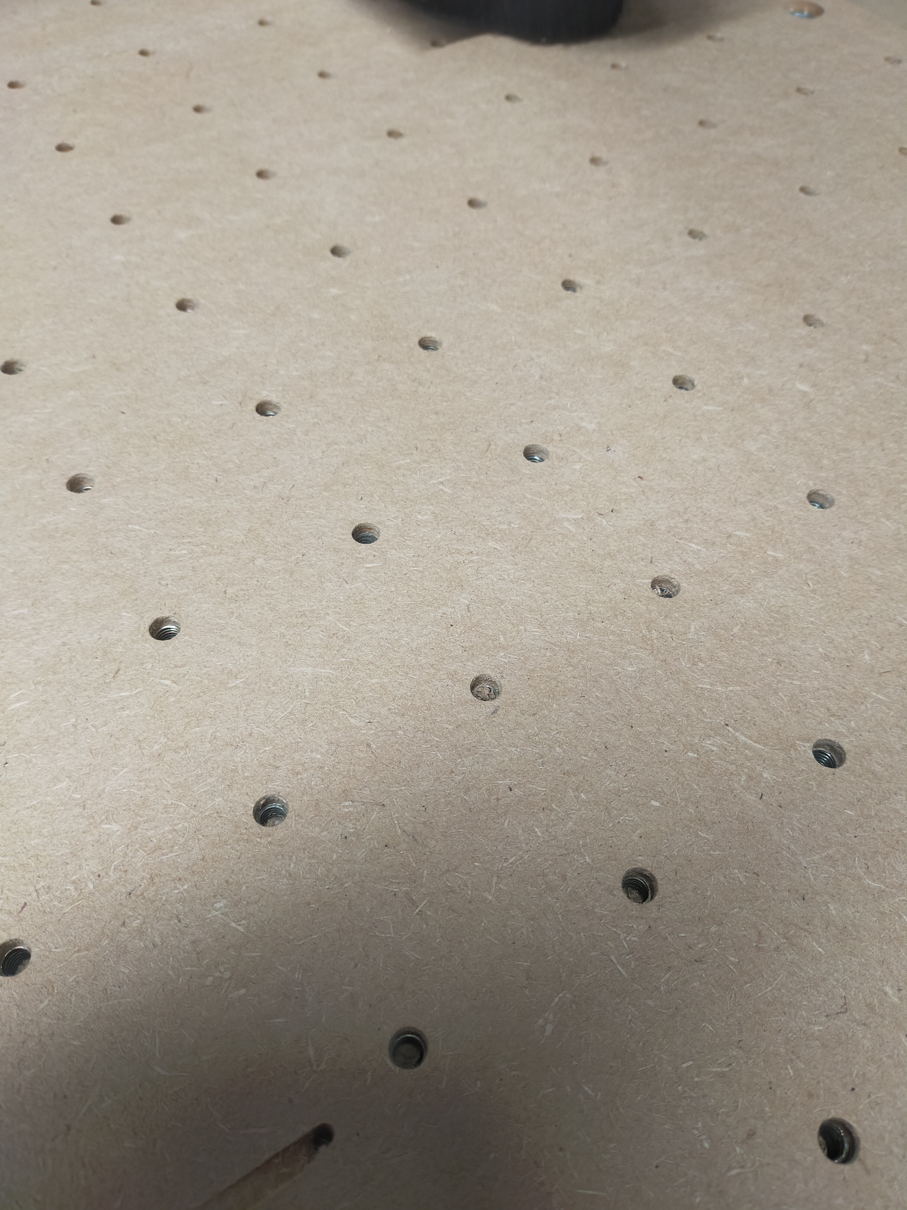
The pallets are all setup for different sizes, and the 6 different screw lengths are catered for too. i have decided to do three pallets for 4, 6, and 10, clamps and screws. The one below is the 6 clamp version, need more clamps, the keen eyed of you should be able to tell why in the first pic :slight_smile:

!

!

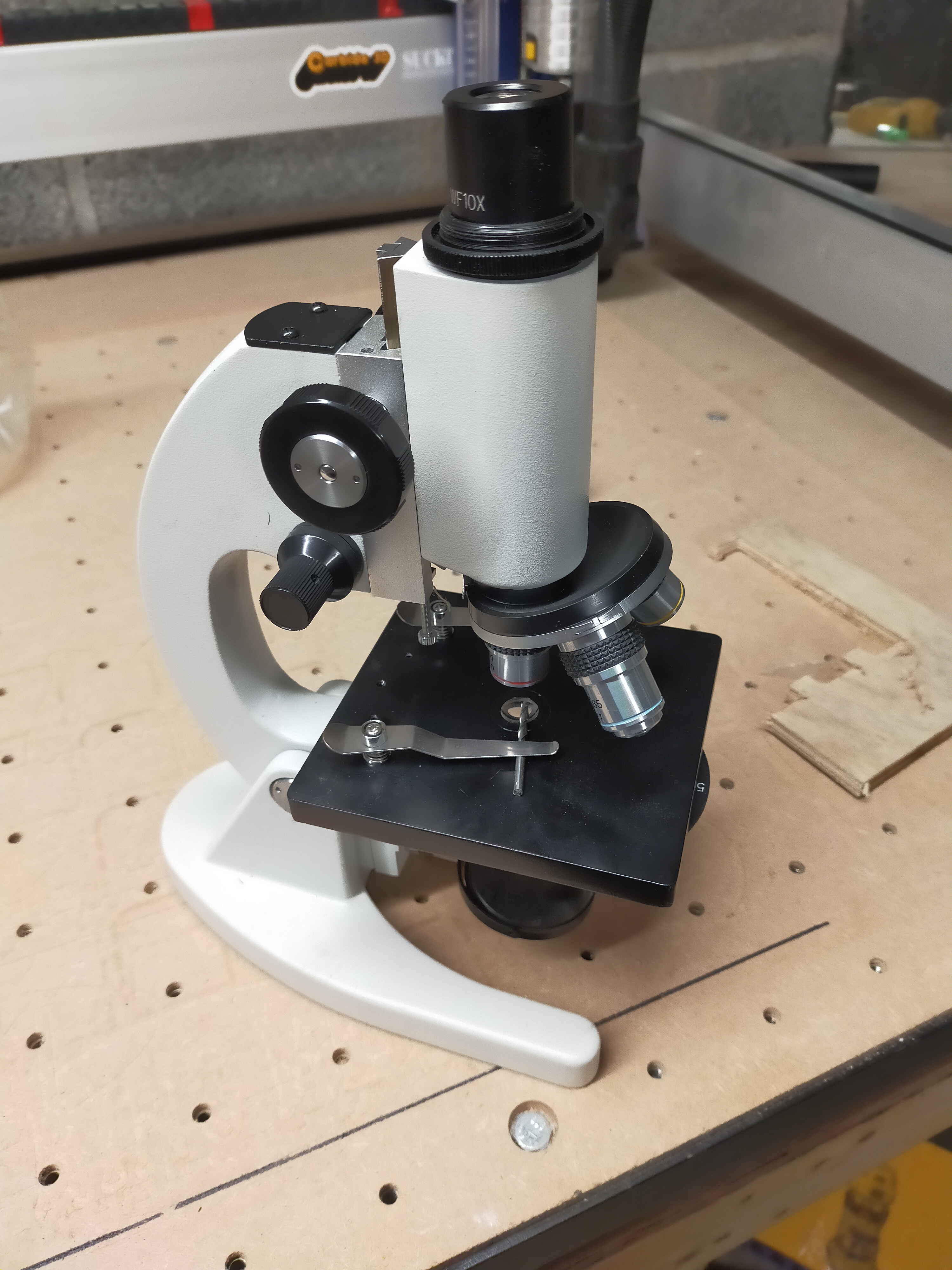
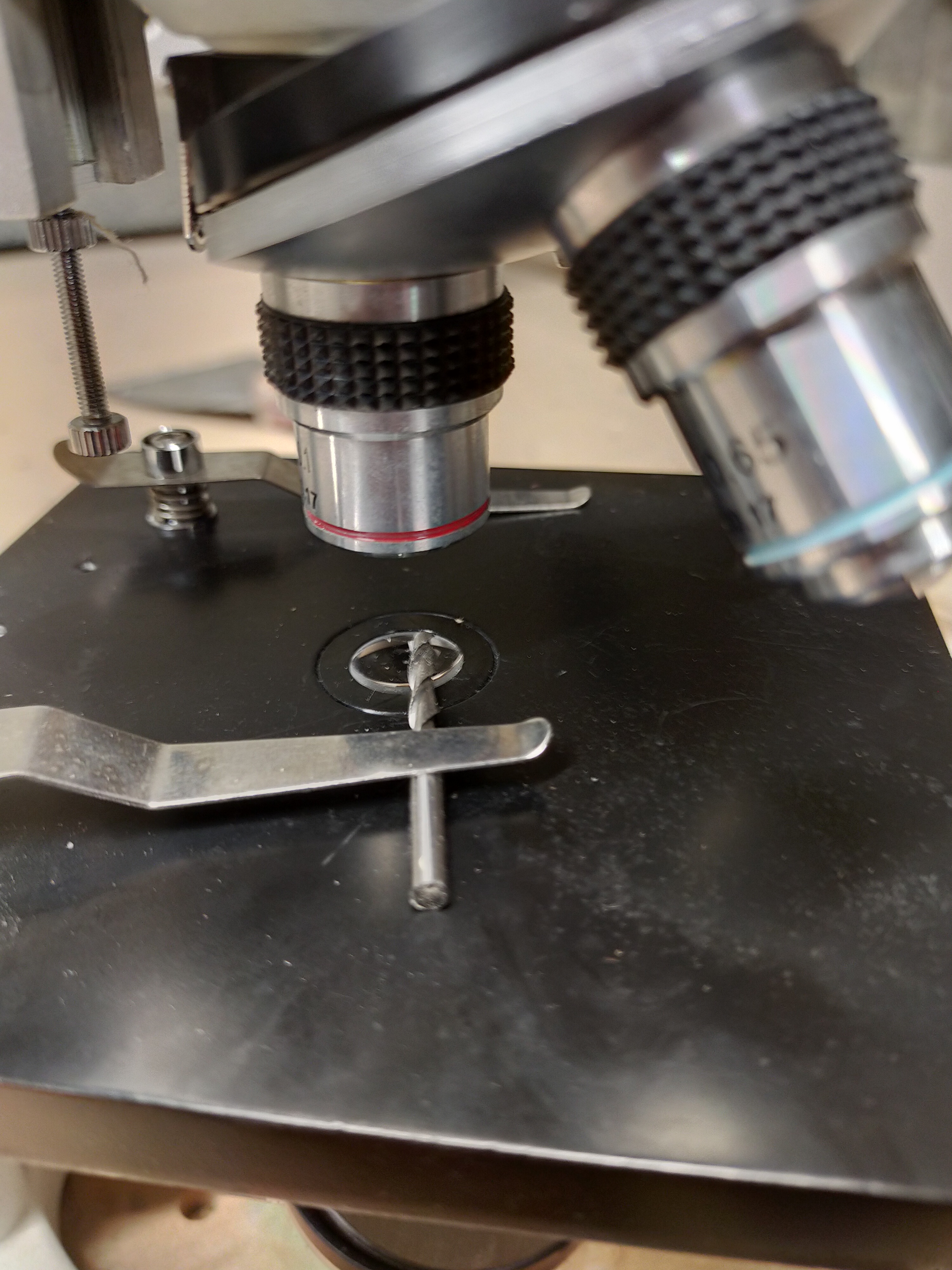
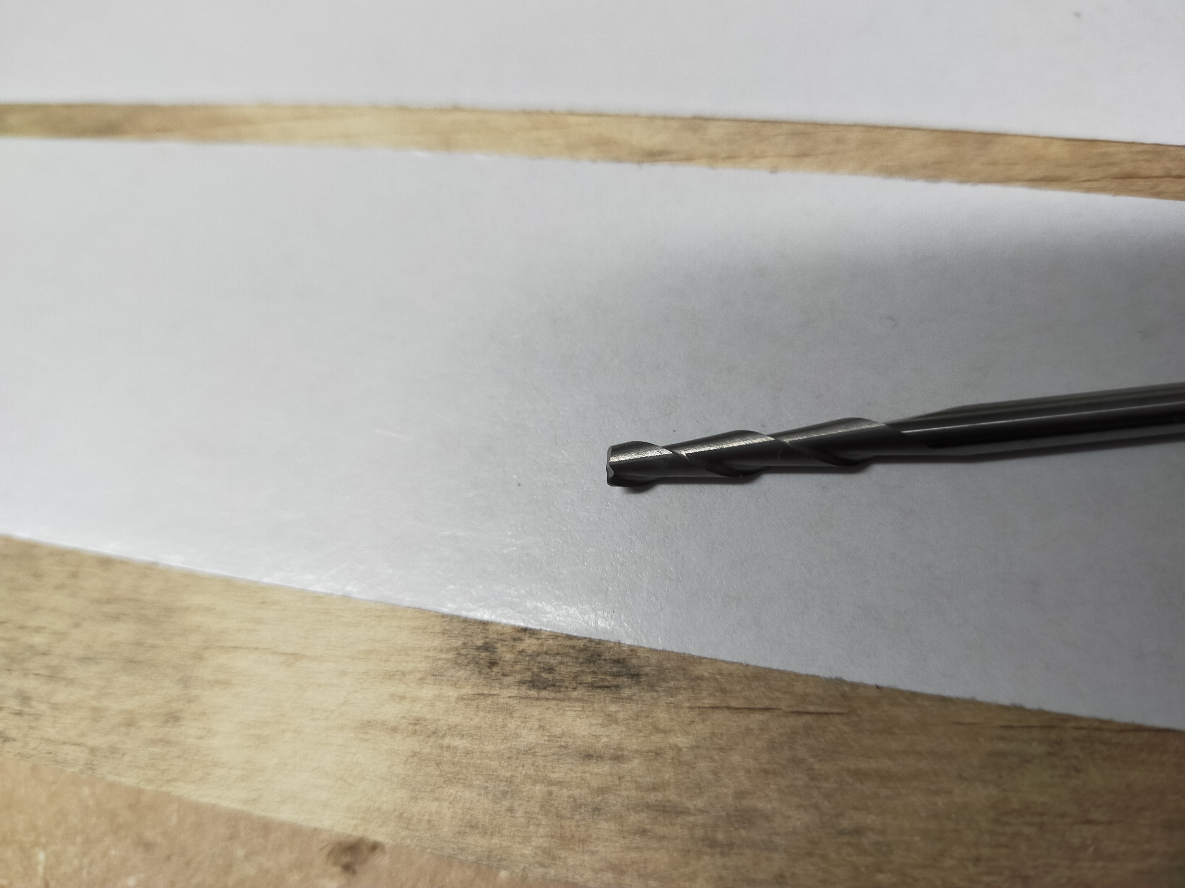
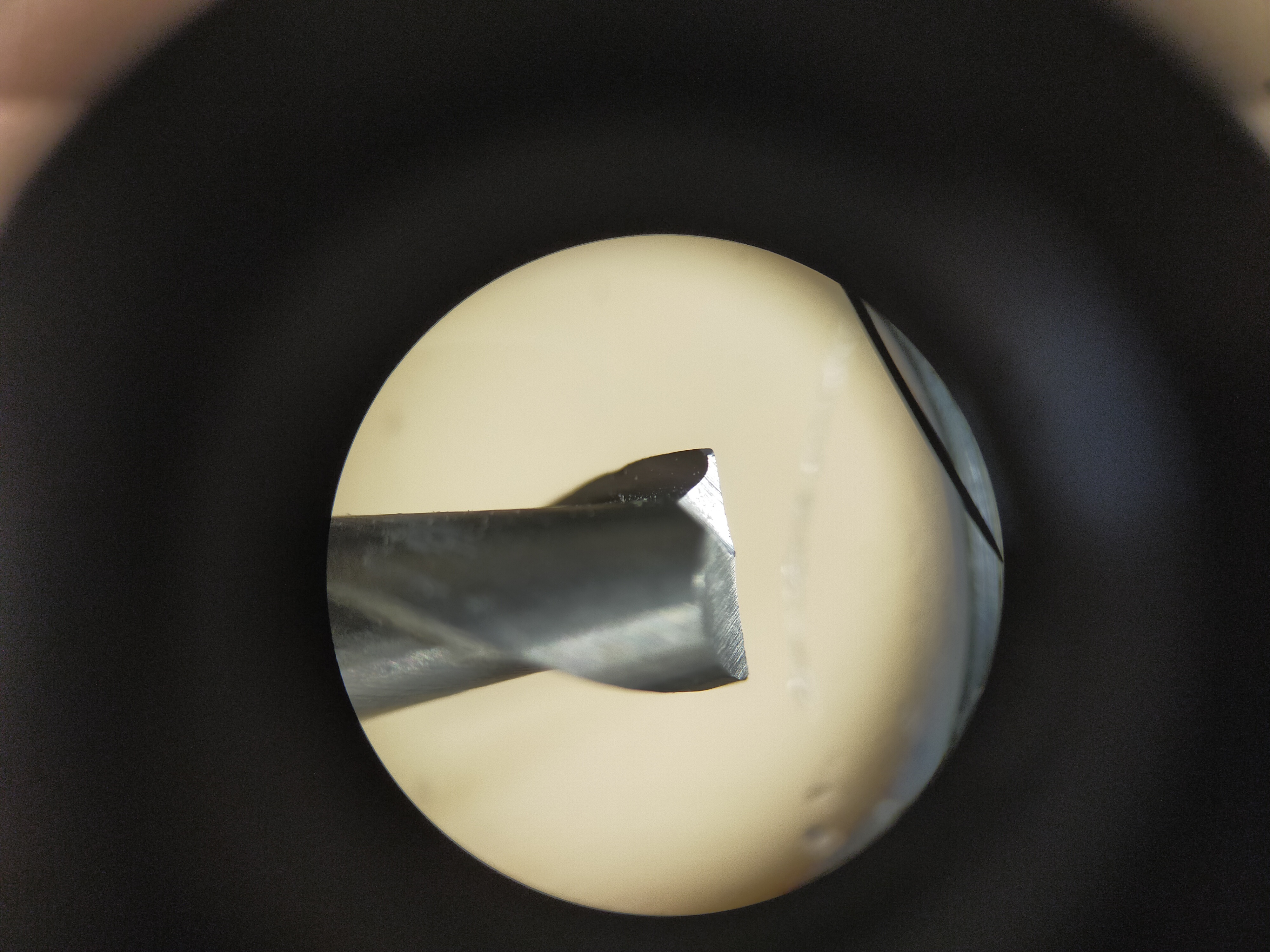
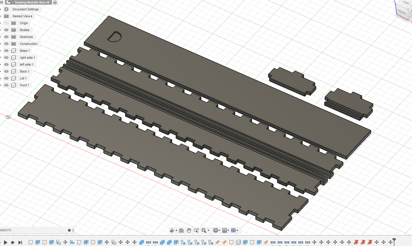
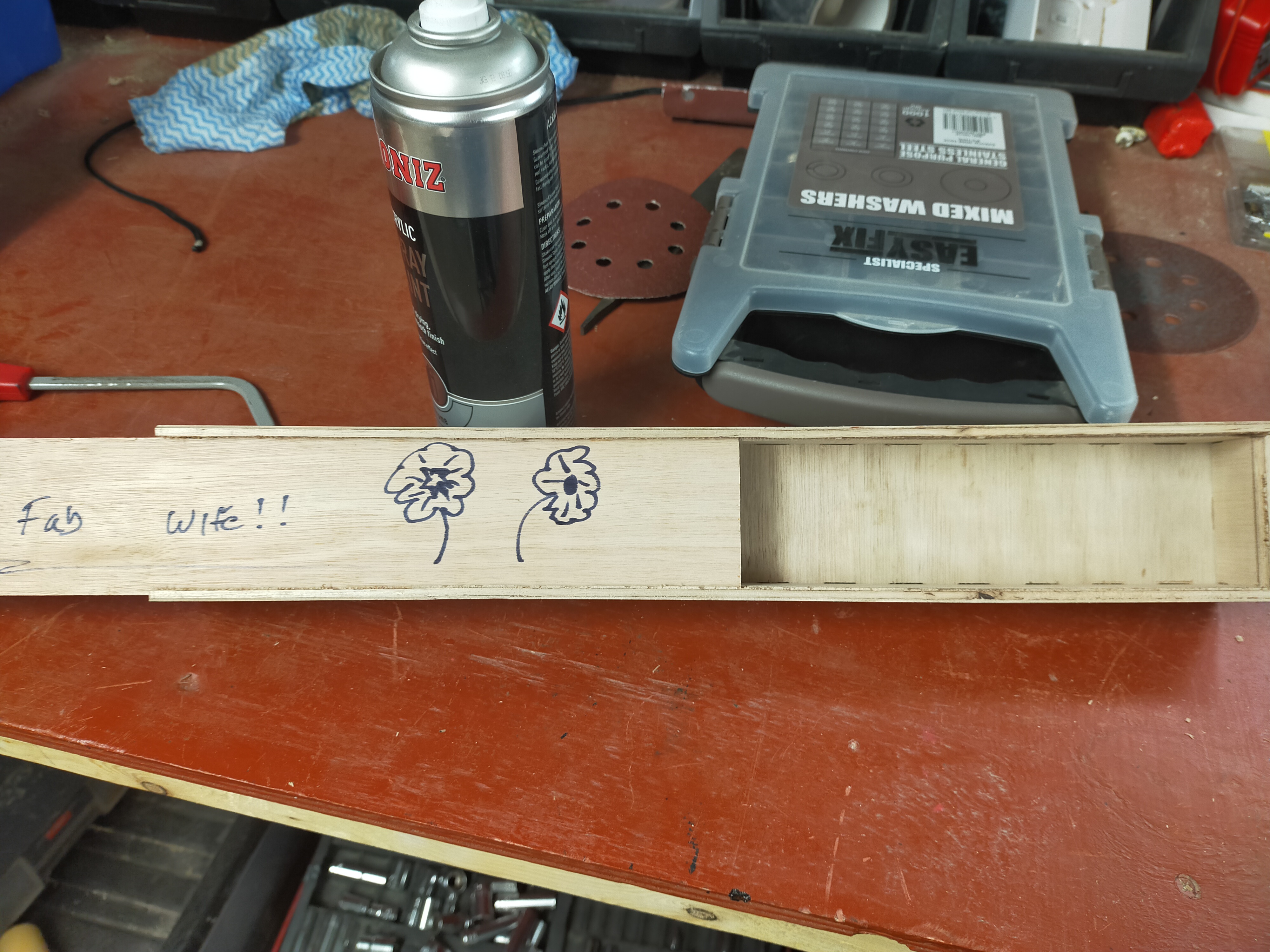
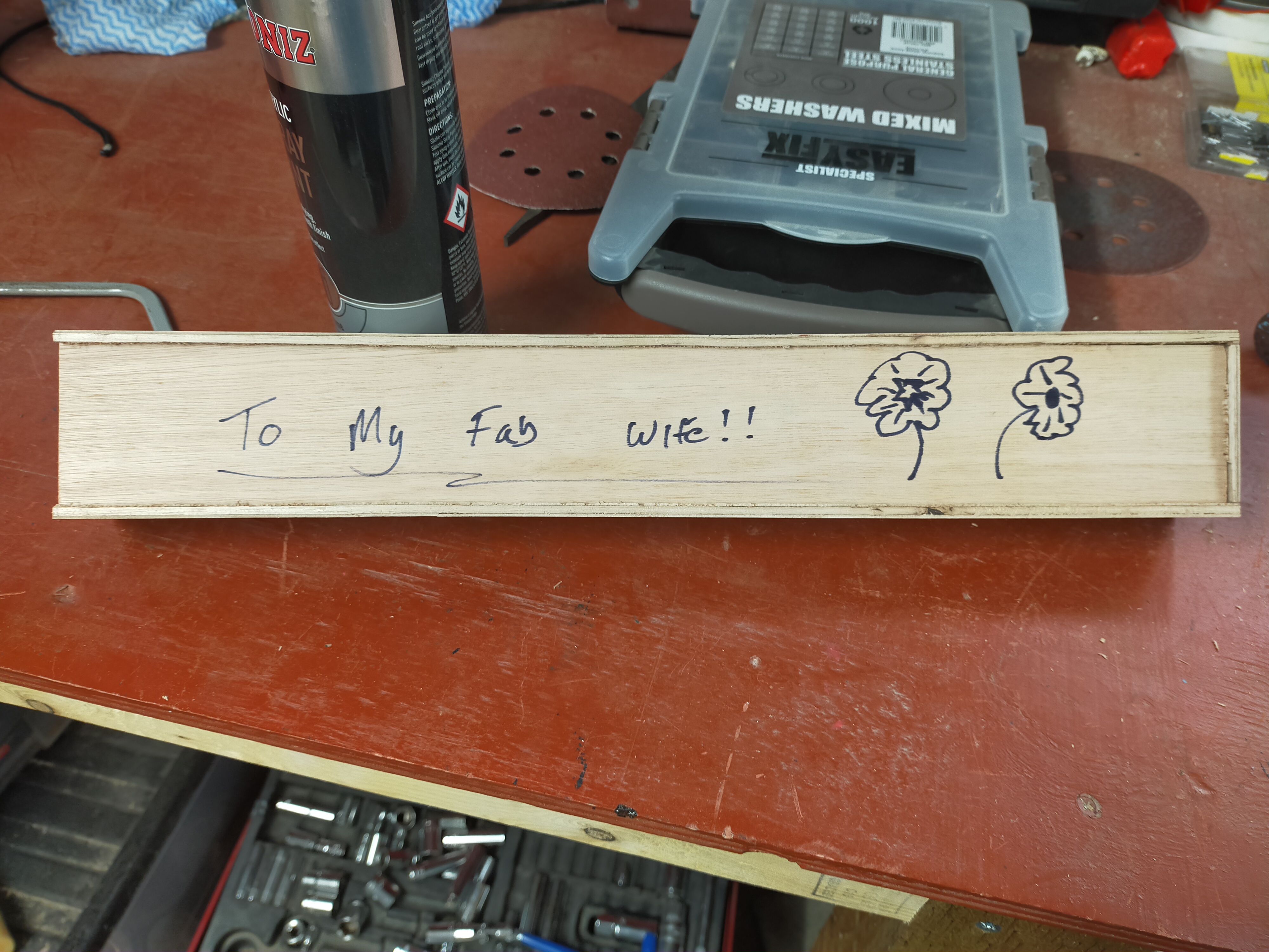
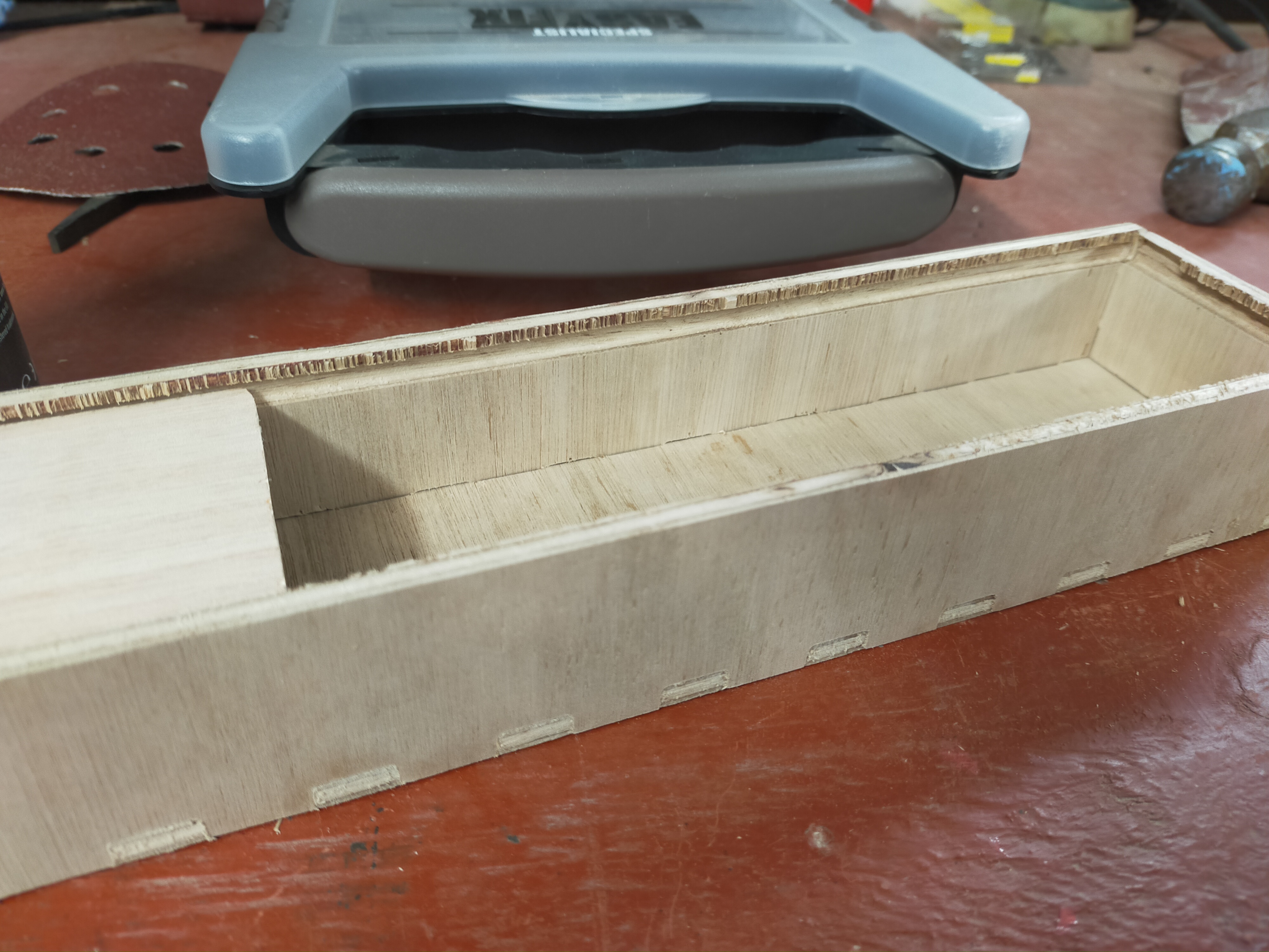
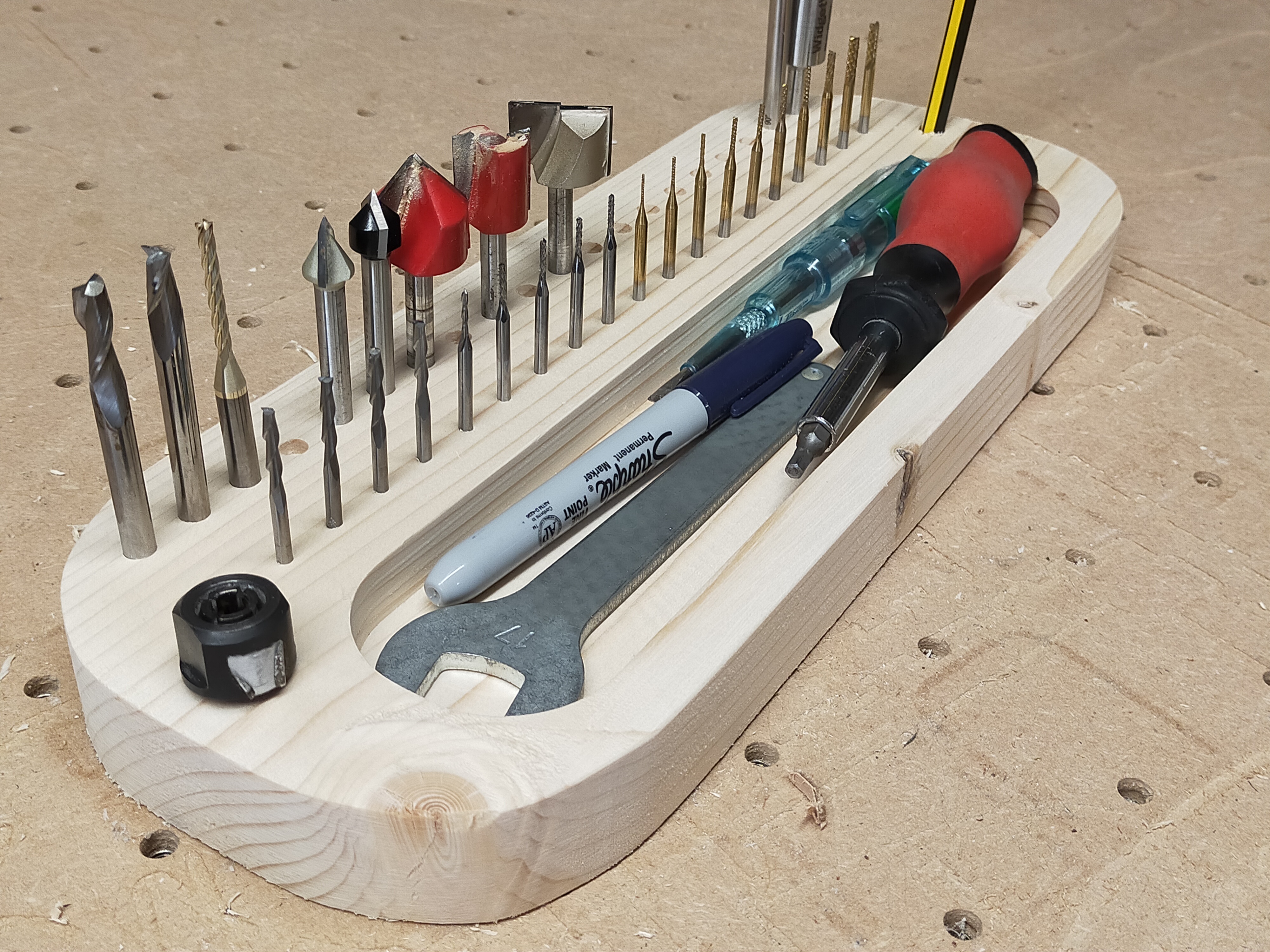
Second - Cutting tool tray type

Design Concept - i want to have these all setup for different job types, for instance a sign making tool tray, HSM tray (clearing Tray), this tray then has all the tools i need to do that job.

The way i work is from left to right, the left tool is the current or active one, i then move left to right if i have duplicates of the tool, shifting left once a tool decommissioned from cutting (hope that makes sense).

This has helped ensure i am getting 100% out of the tools instead of 10% on one and 30% on another. These then sit on my shelf and i pull and work from the tray throughout the Job workflow.

Was really interesting today i felt like it increased my speed, but that might just be because it was new.

!

!

Third - Cam Clamps

Design Concept - never used them before, simple design and needed to make sure would work with my current hold down spacing, not much more to say other than, after trying them, i think i need more than 2 to make this work as it was over torquing (moving the part) with the other clamps i have as above

!

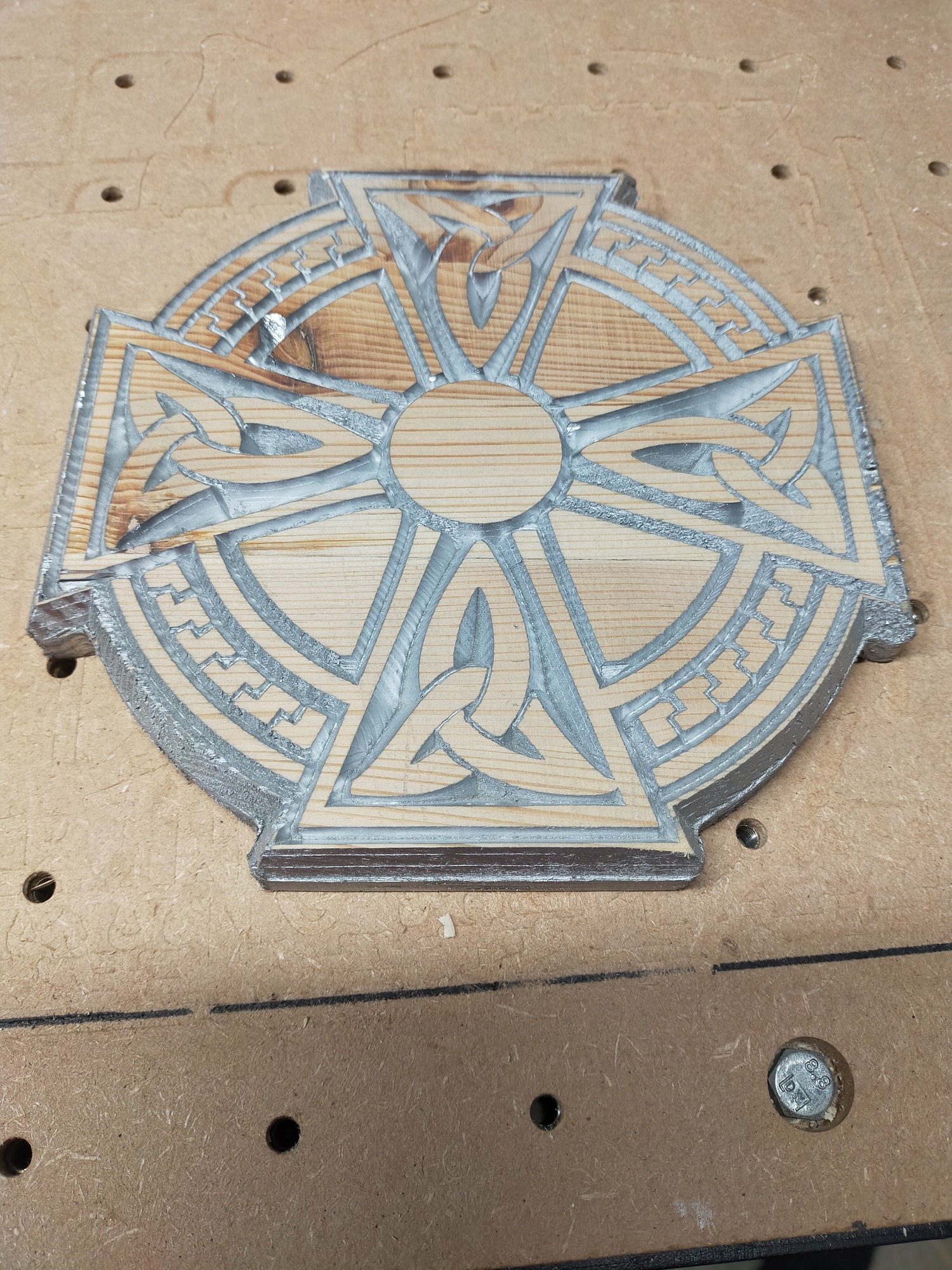
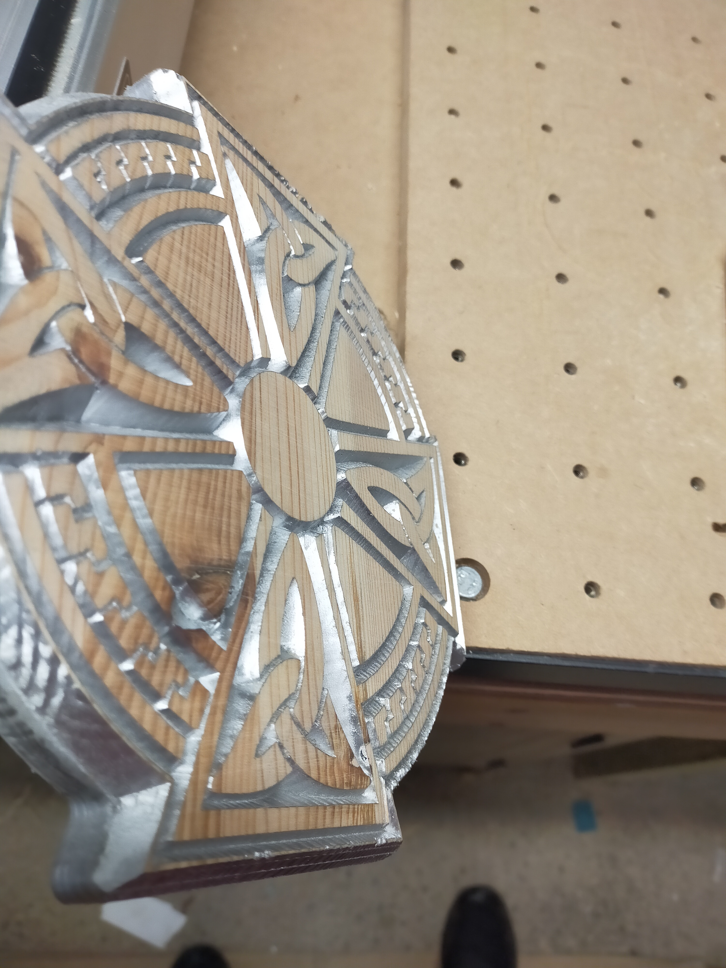
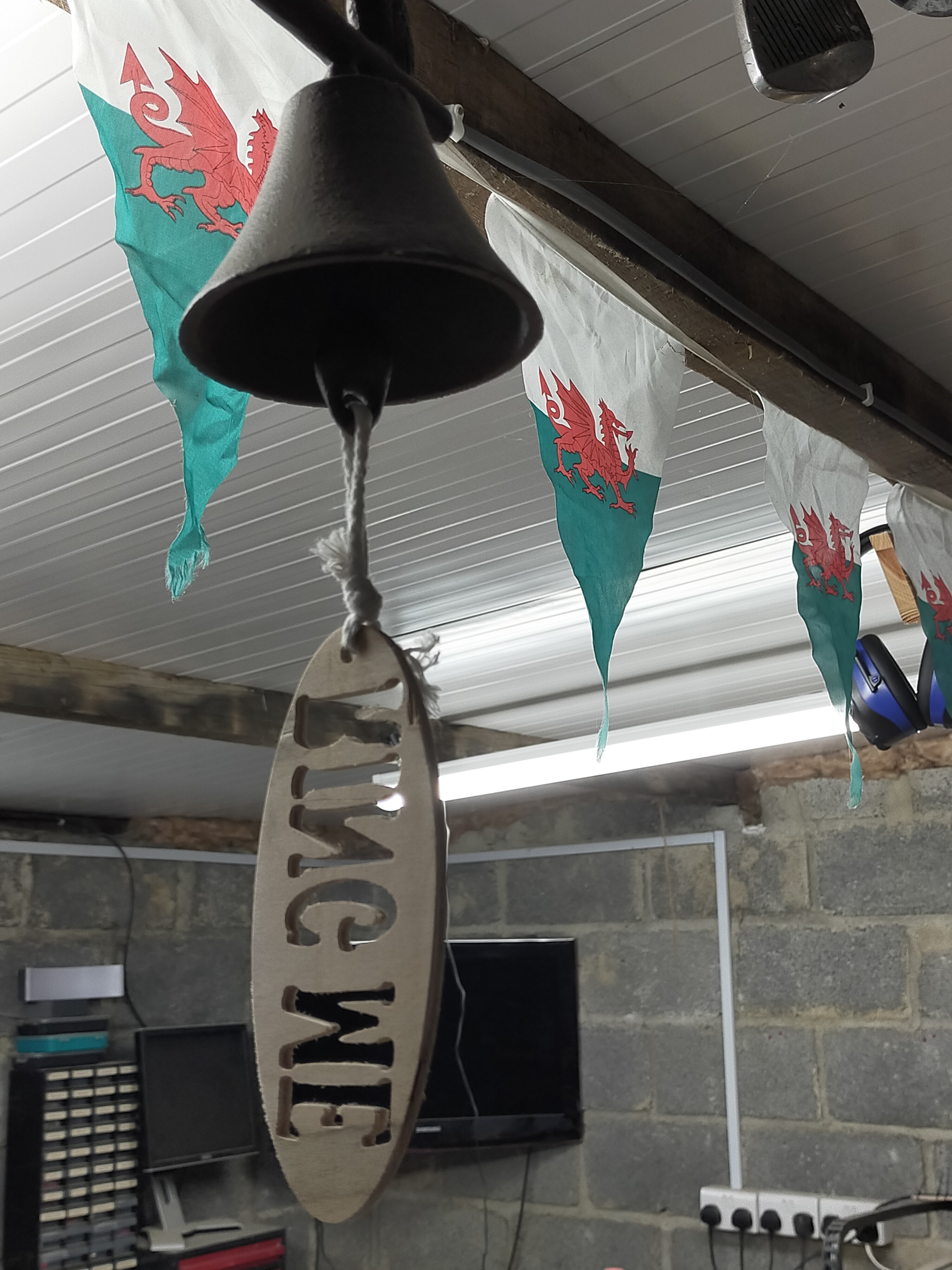
Forth - Bell safety!!

Design Concept - As posted in my contest 10 entry (shameless plug please vote for me Or actually Vote for one of the awesome entries our community submitted) but for those who do not like marketing :slight_smile:

i was frightened by my wife coming into the workshop while the machine was on and i had my Bluetooth ear defenders on listening to music), it was funny but also could have been dangerous as it really made me jump, and if i was doing something on the machine, this might have been a serious.

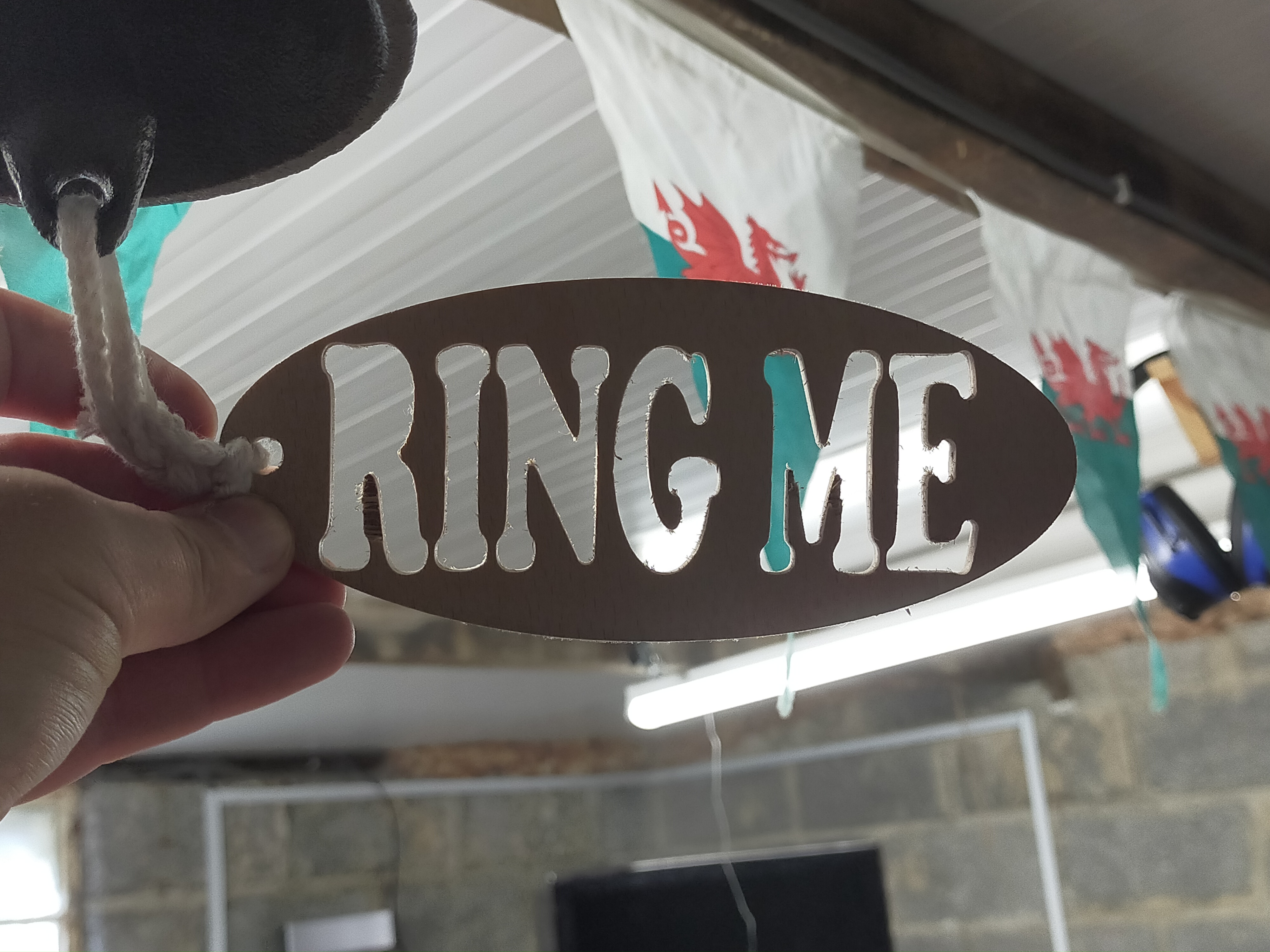
I installed a outside doorbell we had lying around on the ceiling as you come into the CNC room within the workshop, i felt it needed a Do not touch me type thing that obviously pople will notice and touch lol, created a nice little sign tag to go onto the bell string to prompt people to ring, am in the process of creating a sign for the door explaining the rules of entry when machine is on.

!

!

I found this interesting and challenging give it a go, you too can +1 level up your Critical Thinking.

Jon

16 Likes

Jon, it’s very inspiring seeing how you challenge yourself continuously to try/learn new things!
:+1:

2 Likes

Tonight’s 30 min or less tool wear - Pull up a chair and take a look

We all know in theory of tool wear and the need to if possible keep our DOC as large as possible, so the whole tool is used to cut and keep sharp and not just the tip / first 20%. That is why stubby mills are really good, no point in paying for and using a 30mm flute length mill if you only DOC on average 3mm.

I am guilty of this and tonight i wanted to see what this means in practice. To that end. a while back i bought the kids an old laboratory microscope off ebay, and we use it now and then to looks at things, so tonight i decided to examine an end mill i have been slotting with, The first rule if slot club is to admit you do it!

Here is the microscope :slight_smile:

This was ace fun and really interesting to say the least, and i will be buying a microscope i can connect to my USB / screen later :slight_smile: For science you understand!!.

The pics below are taken with the phone up against the aperture of the microscope

Now then to the eye there is nothing special about this little 3.175 / 2 flute up cut mill, other than i have been slotting 80% with it, but the last couple of cuts i noticed that i was getting funny streak lines on the floor of my cuts, and the side was was, well best way i can describe this is a sort of wave pattern.

So lets see if our eyes can see anything.

Nope nothing to see here!

!

Lets take a closer look

!

Can you see it there are two defects here -

First one is on the top flute spiral, follow it back, and you can see a semicircle inverted dent.

Second one is just below centre you can see what looks like a white dot / glare. You will see in a second that this is what i think is causing the bad floor finish.

OK spin the lens and in we go!

Notice the up cut striations spiralling upwards counter clockwise

Well, will you look at that. Now that is a nice chip for sure, but not the type we like. Lets see if i can get closer, in we go

!

Amazing, a clean slice right out of the bit and in the second picture you can actually see the slice, with the naked eye this looks fantastic.

!

!

This last one i simply could not get it to be in focus with my phone, but with the naked eye you can see a perfect wave on the edge that clearly matches up to my wood wall pattern,

!

The following high detail scan and CAD model will better explain what i mean!

Fascinating 30 mins, and something i am going to do more often before i blame my SO3 !!

Hope you enjoyed this little experiment

Jon

13 Likes

Ok so this is a funny one chrome spray paint on vcarve , goal here is to get this toolpath down under 30 mins Mission complete.

The paint is hard to photo but really cool / odd finish, parts look like metal see what you think

5 Likes

Maybe the “knothole” limits the metallic effect. :smiley:

4 Likes

Ahhh I see. What
happened here @CrookedWoodTex it is a simple mistake you meant to say rust spot lol😁

3 Likes

Seriously, I have milled a very nice looking gold bar that I managed to shellac and polish/sand enough to look fairly real … out of MDF.

I’d bet that silver would look much more realistic if you cut one of those intake manifolds (that @Vince.Fab makes) out of wood and used many (8 or more) coats of shellac with sanding each layer to make if really shiny silver.

5 Likes

So what did you do to the toolpaths to get it down to under 30min? What was the toolpath time before?
Inquiring minds want to know.

Pull up a chair :grin:

First increased the DOC I have started to realise I have been too soft on my machine, so that increased by 2 mm to 3 mm

Second revised feeds and speeds increasing by approx 50% from feed rate 1334 to 2344 this is as fast as I can go based on hardwood testing

Third, rather than running a finishing cut at different F&S, I ran a second with my doc ,5 mm deeper so does in one pass no air cuts

All those combined gets me sub 30 mins

2 Likes

Getting Son number three hooked. Mission accomplished!!

So a few 30 Mins here -

1st Get son interested into CNCing by complete a project for school
2nd - Real life example for my son on step over and a very large scale - best example ever!
3rd - Review of a fusion 360 Plugin (not affiliated in anyway) i just found it very useful so thought i would share my experience

OK here we go

1st Get son interested into CNCing by completing a project for school.

Simple one here needed to create something quick as he had - as we all do, left his work to the last nanosecond, so we worked up a plan, on creating a house that needed no glue - any material allowed. (cool challenge by the way to the Technical Teacher in the school)

So we decided, as i have been working with automating finger joints in Fusion i would give it a go with finger joint design house, with tight joint tolerance to require some hammer tapping to hold in place.

He sketched around for a while and we settled on this design. More on the finger joints to come.

Discussed and described why and what nesting is, and he set about working with maths (even though he refused to acknowledge it lol) to get the shapes nested and positioned. I think we can all agree that he understood the nesting lesson - hardly any wastage here.

Next we use a hammer and with a little liberal use of the “persuasion stick” it fit like a glove - and also the smile is x2 1)because he was 1/2 way to meeting the deadline 2)who does not like using the hammer !!

This Came out really well and i love the touches he did in Fusion to try and make the door and windows appear 3D, as if they are opening in, very proud of my young man and he had a fabulous day off the PS4, and is already working on another project, soon i will not be able to get on the SO3 lol!!

Well done Him! - Finished Article

!

2nd - Real life example for my son, describing step-over on a very large scale - best example ever!

So Whilst we are working and i was finishing off a job, i was asked what is step-over, i tried to explain using % of WOC etc and it just went Whoosh over his head… so i did this in our field i said :-

  • The lawn mower if the Bit
  • The gaps in the grass is the cut,
  • The green line (uncut grass, is the step-over)

Then i said to him after taking the pic - Stepover is defined as the the space between passes of a tool during an operation, and click he now has it locked in

3rd - Review of a fusion 360 Plugin (not affiliated in anyway) i just found it very useful so thought i would share my experience

So first off please C3D is this review breaks any post please let me know so i can remove as i would love to keep my thread, but this is not a sales pitch or a hard sell, just an honest review from a nobody :slight_smile:

Again i do not know this company / person, now that is out of the way onto the problem - solution - result

So the Problem - Faster way to create finger joints in Fusion 360 other than my current mathematical way (and was taking me ages but worked)

What i would do is create the design then using bodies i do the following:-

I would create the male part, and align it with the female, then using the “Combine + Cut Finction” would then get the female shape i needed.

Align

Combine + cut

So a little bit here - Blue shading = Target Body Red Shading is the Tool (or what you want to cut / join / etc) Importantly the tick in Keep Tools means that the Red Body will remain after i complete the operation, and as this is the side of the box i need to keep it, otherwise after the operation it deletes the body.

Once i complete this and then move the bodies i get my finger joint.

But the keen eyed of you will say hang on what about join tolerance, well this is the mad bit now, i need to give these dimension constraints, these then give the desired fit, takes ages but works.

The issue with this is, well nothing other than time, and to me as i work full time too, my time in design is precious, the longer it takes to do simple things (in my mind) is less time cutting = less profit and me still staying in my full time job :slight_smile:

The Solution Whilst on a fusion 360 course someone mentioned this plugin - mortise and tenon fusion360 addon so i did a trial and was sold, it takes seconds to do what took me ages.

So in order to do this you need to work slightly differently, first make your box.

then simply activate the add-on, it then asks for some parameters that quickly define your joints:-

Board and face is how you construct the joint, so for us in this review the board is on the X plane and the face is on the Y, once both selected it then take into account the other selections:

Depth is the depth of the join (i use parameters so here do “Mdepth”) if not using parameters just put you material depth here so i did 10mm

Length is the length of the fingers i want - here i have done 15mm

Number of Tennons = how many joint you would like

Offset 1 gives the offset the joints are computed on , no offect would result in joints being flush with top and bottom of the body face, we have done 15mm offset so our joints are offset from the top and bottom by 15mm

Centred = joints will be, erm centred in the body :slight_smile:

Fillet radius = turning then joints from square to having a fillet radius as defined by your mm entered (see later pic for fillet)

Length offset = joint tolerance either make the join larger or smaller, so with a .20mm offset set this would mean our length defined above 15mm would then be 14.80mm if that was a 1mm it would be 14mm (my testing has provided best results between .20 - .75 )

Thickness offset = same as above but the thickness would be reduced by the defined amount

with all that set you get a nice preview of your selections - as thus

Same inputs this time without offset 1 defined

with fillet radius defined at 5mm

so once accepted you get this

so i am very happy and impressed, now what used to take me an hour of tweaking etc takes seconds (honestly)

it costs around $30 USD or roughly £24 GBP - so is it worth it? - to me yes because i feel confident that the time it has saved me so far is easily in excess of it’s price tag.

The Result So you can see the house above and here is a Fusion view of said design

and a knitting needle box test for my wife : - (happy with the joints, but the lid slide, plywood splintered in hardwood think this would have been ok)

So there we go, hope you found this interesting, as always any questions / queries please lt me know, do my best to answer

Jon

12 Likes

Good job getting your kids interested in cnc!
Any amount of time you can get the kids away from the computers/consoles is great.
This coming from one that has wasted too much time on useless games.
Every creative soul saved from gaming benefits us all.

2 Likes

Jon, great to see kids doing something; anything. :smiley:

As far as your box joint’s fit, do you round the pins or square the sockets where the two meet?

1 Like

Depends on design but typically both are square and the softness of the wood allows the joint to be compressed, where that is not possible I keep the finger square and joint has small dog one / Mickey mouse ears if that makes sense. To allow flush fit

2 Likes

When you say “square”, do you mean you cut them with a teeny-tiny diameter bit?

2 Likes

OK so @CrookedWoodTex this is what i was trying to say.

Correct i use a 1/8th 3.175 mm or 1.5 mm flat end mill to get as close to 90 Degree cut as possible, in wood 90% of the time i find that this gets me close enough, but on the cases that i cant then i use dogbone technique as below

This was a test with 1.5mm end mill (no bone)

this was same cut but with dogbones enabled in the CAM Cut

That make it clearer? if not let me know happy to explain further if needed :slight_smile:

3 Likes

Great. That is what I expected, but didn’t see in the Fusion stuff. Thanks for the clarification.

Quick one today - refacing after three months “It is said that a person’s happiness can be measured by the lack of tram lines in the facing toolpath” - Jon

So taking this quote of mine, I am going to sleep a happy man

1"flat bit
Doc .25mm
Stepper 39.8%
Fr 3218

Shot and sweet for this update, hope you are all safe and well people

8 Likes

Those are very true words! What technique did you use to tram?

1 Like

One that dam near killed me lol, i use a dual dial edge pro tram and allot of coffee and shims, I tell you what I will do is another 30min write up for you if that would help?

Jon

3 Likes

That would be great. I’m always interested in other people’s processes. 30 minutes isn’t too bad; it took me way longer than that the last time I adjusted the tram.

3 Likes