Inspired by a request on the Shapeoko and Nomad Users Group (Unofficial) Facebook group.
How to create a grid for my 5 Pro 4x4?
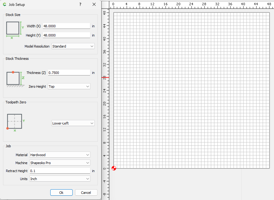
Job Setup ![]()
Your work envelope is 48.7 x 48.7. Let’s create a grid 48x48, and we’ll start 0.35" from the extreme lower left corner.
Set your Width & Height to 48, Thickness is not important here. Zero Height: Top. Toolpath Zero: Lower-Left. Retract Height: 0.1. Units: Inch
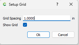
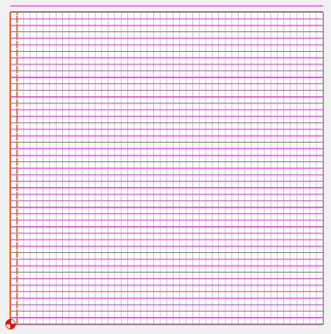
Grid ![]()
Set the grid to 1.0, and check “Show Grid”
Draw the grid
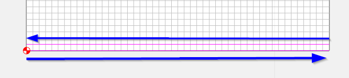
Create 2 Polylines ![]() , one from the lower left to the lower right corner. And one from the next grid line up (1") but draw this one from right to left. (You’ll see why in a bit)
, one from the lower left to the lower right corner. And one from the next grid line up (1") but draw this one from right to left. (You’ll see why in a bit)
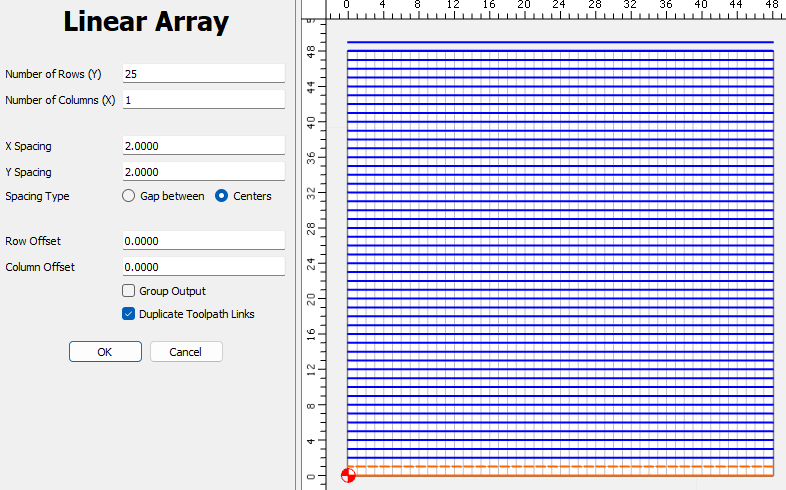
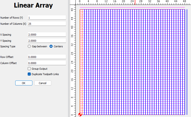
Select both lines (Hit Ctrl-A to Select All), then select the linear array tool ![]()
We’ll make 25 rows, 1 column, and set both X & Y spacing to 2"
Now repeat the process to draw 2 polylines on the left edge, and 1" in from the left edge.
Draw the left edge from top to bottom, and the next one from bottom to top.
Select them both and use the Linear array tool again. This time 1 Row, and 25 Columns.
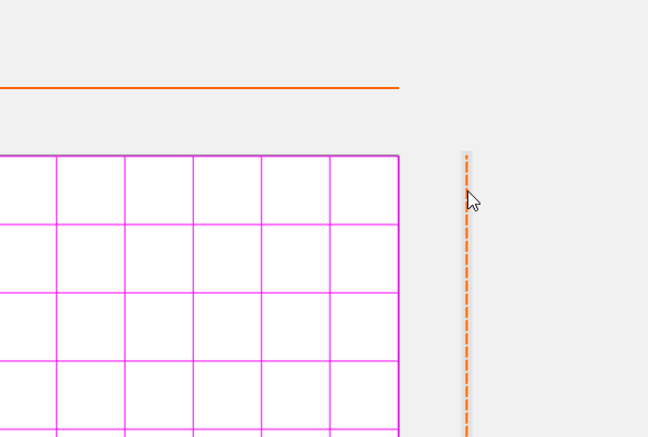
Now let’s get rid of the 2 extra lines. Select them both using the Shift key to select the 2nd line. Then hit the delete key.
Toolpath
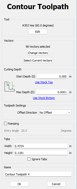
Now go to the Toolpath tab. Use a rectangle or Ctrl-A to select all of the vectors. And create a Contour toolpath. Select “Use Current Selection”.
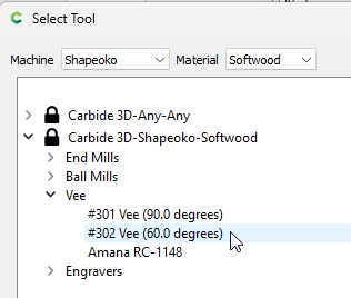
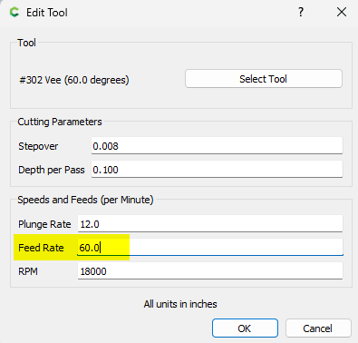
We’re going to select a Vee Bit tool. Select “Edit”, and then “Select Tool”. Set the “Machine” at the top to “Shapeoko” and the “Material” to “Soft Wood”. Select the #302 Vee (60.0 degrees) tool.
We’ll accept the default parameters. But let’s change the Feed Rate to 60
There should be 98 vectors selected. Leave Start Depth at 0.000, and change the Max Depth to 0.0001. If your post is set to 3 decimals for Inch, this will output a cutting Z of 0.000
Set the Offset Direction to “No Offset” to cut directly on our lines.
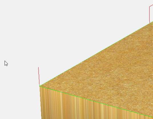
Hit “OK”, then in the Simulation panel set the material to MDF. Make sure all 3 checkboxes are checked, and “Show Simulation”. Rotate the part (Mouse button 1) so you can see the toolpath.
Zoom into the lower left corner. Notice the engage move has some green at the bottom. This is where the toolpath starts. Not always easy to see, but the final retract will be all red.
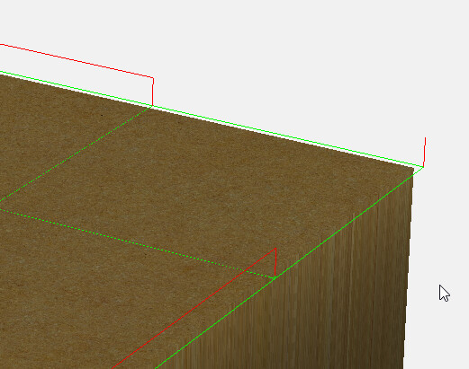
Also notice the Red Rapids are all short & jump directly to the next line to be cut.
This is why we alternated the direction of every other polyline. Had we just copied a single line with the array tool, the rapids would be all over the place.
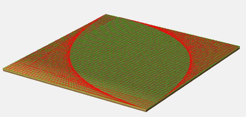
Pretty!! ![]() But will waste a lot of time.
But will waste a lot of time.
Save
Now save your toolpath. Select the “Save Toolpaths” button. Select “Save toolpaths to this file”
(If you have Pro, and want to use a G-Code file, you can select “Save as G-code”)
Send the file (Either the .c2d file, or the .nc file if you used G-Code) to the machine, after initilization move your machine to the extreme lower left. If you use the Quick Position, make sure you jog to the exreme -X & -Y until the machine stops. Set your X & Y zero, then jog 0.35" in both X & Y, and set your XY zero again. Touch off your tool to the top of the spoilboard. Set the Z zero, but instead of clicking the button, enter the depth of cut you want in the Z text box (0.010) and hit ENTER. Look at the digital readout to make sure Z says “0.010”. Now you’re ready to make your cut.