I own a Pro XL and I upgraded the bed with Saunders Machine Works fixture plates along with the SMW vise. I mostly cut aluminum. I know that this is a special case that doesn’t necessarily relate to what most people here are cutting, but I get the impression that this kind of setup is growing as more people are getting the HDM (and Pro?) to cut metal.
I find that I almost always end up cutting on 2 or more sides of a part and I need to be able to accurately establish a zero point by referencing off of features I cut on previous operations. For example, here are two parts I machined yesterday:
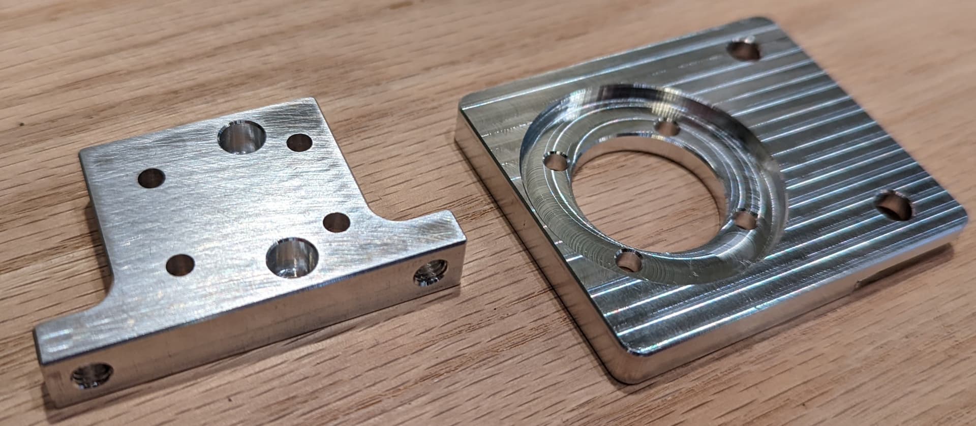

The part on the left has six 3.5mm through holes where 4 have a 6mm recessed hole on the top and 2 have a 6mm recessed hole on the bottom. The side of the left-hand part has M5 threaded holes in it.
The part on the right has a cutout on each side, 5.5mm holes and 3.5mm holes. Both parts have all the edges on the sides I cut chamfered and all the holes chamfered.
I’m sharing this rather long post to hopefully help others as they head down the same path of trial and error that I followed. Hey, I might even get lucky and someone will read this and tell me how I’m doing it wrong and give me an even better solution!
Initially,I tried various manual approaches and found that I couldn’t get the accuracy I wanted. Finally, I started playing around with making my own manual probe.
If you want to keep it really simple, you can create a great probe super-super easily by hooking up a battery to buzzer or a light and connecting the ground through the spindle nut (positive goes to buzzer, negative goes to spindle nut with a connection from the bed to the negative of the buzzer/light to complete the circuit when the end mill touches).
I made a couple of prototype probes along these lines and, while it worked, I wanted a better version. There are two things I didn’t like about this super-super simple approach:
- It runs (a tiny, “who cares? But it bugs me” amount of) current through the whole setup, and
- the buzzer is really loud and annoying and the light requires that you be looking at it to work so neither was very pleasant to use.
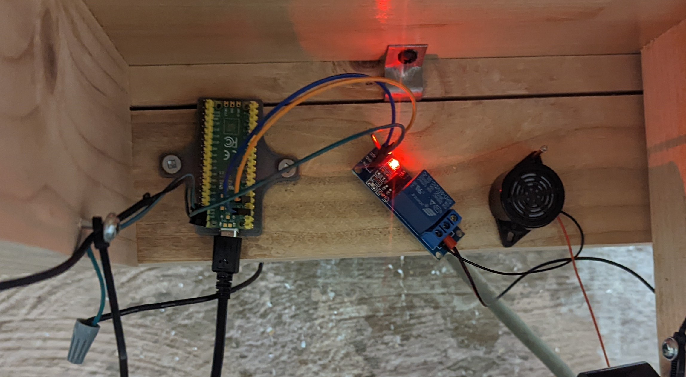
To make it more usable, I added in a Raspberry Pi Pico and a relay for the buzzer. Using the Pico lets me control the audible noise and make the probe a dry contact instead. Here’s a picture of the pico / relay / buzzer:
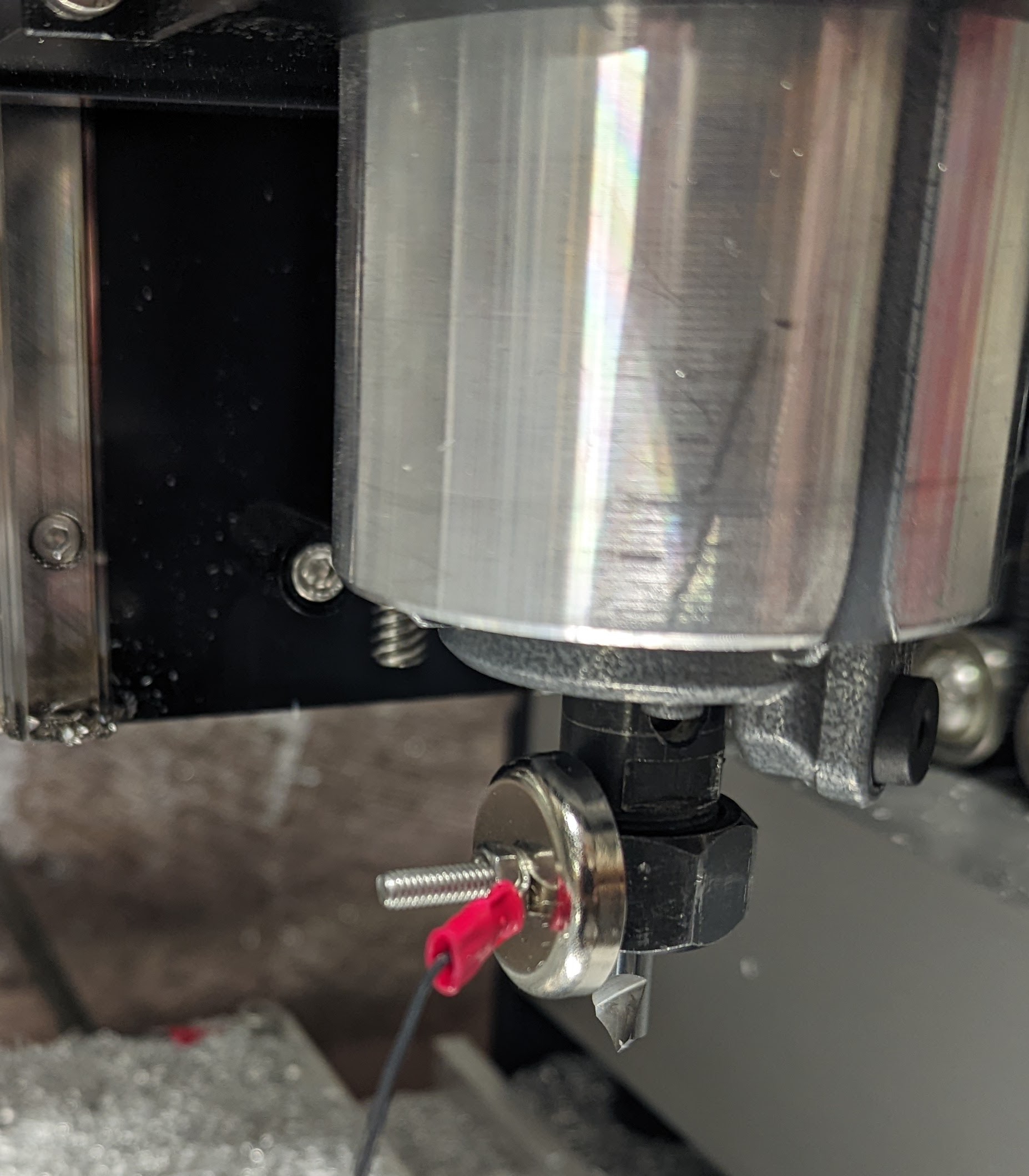
When I want to probe, I attach a magnet to the collet nut that is wired to an input on the Pico. The Pico’s ground is also connected to the fixture plate (you can just barely see the ground wire under the pile of aluminum chips):
When the input (spindle nut) is connected to ground, the Pico uses the buzzer to make 10 quick bleeps followed by slower bleeps after that. The 10 quick bleeps grab your attention and avoid accidentally jogging past the trigger point. I opted to have it to keep bleeping to remind me that I am still touching the stock and to keep that in mind when I start jogging again.
To establish a rough X/Y zero (e.g. off of unmachined stock), I just touch whatever end mill is loaded against the stock and set 0 to be offset by half the end mill diameter.
To establish a very accurate X/Y zero, I try to use the middle point between two probe points. Either the two inside edges of a hole or the two outer edges of a feature. As long as you are using the middle between two points, the probe diameter cancels out and you don’t have to worry as much about the precise size of your probe. For example, I often use the back side of a single flute 90 degree chamfer bit because that was the last mill I used on the previous operation. For very small holes, I have a tiny end-mill I use (0.5mm?) and or I also sometimes use a 0.25” gauge pin for really important zeroes.
Most of the time I am cutting with Z as the top of the SMW vise. To establish this, I put the gauge pin in the router and jog until I touch the fixture plate. I then set my location as -25.4mm which is the height of the built-in parallels on the vise.
If I need to set Z zero to the top of the part, I jog until it touches the top surface and simply set that as zero.
With this setup, I can get “perfect” repeatability. The step resolution of the Pro is 0.025mm and I can repeatedly probe the part and it will trigger on the same step each time. I can’t easily measure accuracy, but it’s accurate enough that I can flip the part and run a 0.2mm chamfer on a 3.5mm hole easily and accurately after flipping the part.
If you are using a different gcode sender, you can probably keep this same setup to allow manually probing and then simply connect the wire going to the magnet to the bitzero input pin on the control board. That would give you the option of automatically probing or manually probing depending on your needs.
Or you can probably lose the Pico, etc. entirely and just run the probe wire to the bitzero input, but I didn’t feel like trying that because I’m staying in carbide motion for now because I have a workflow I’m used to in it.