Hey there,
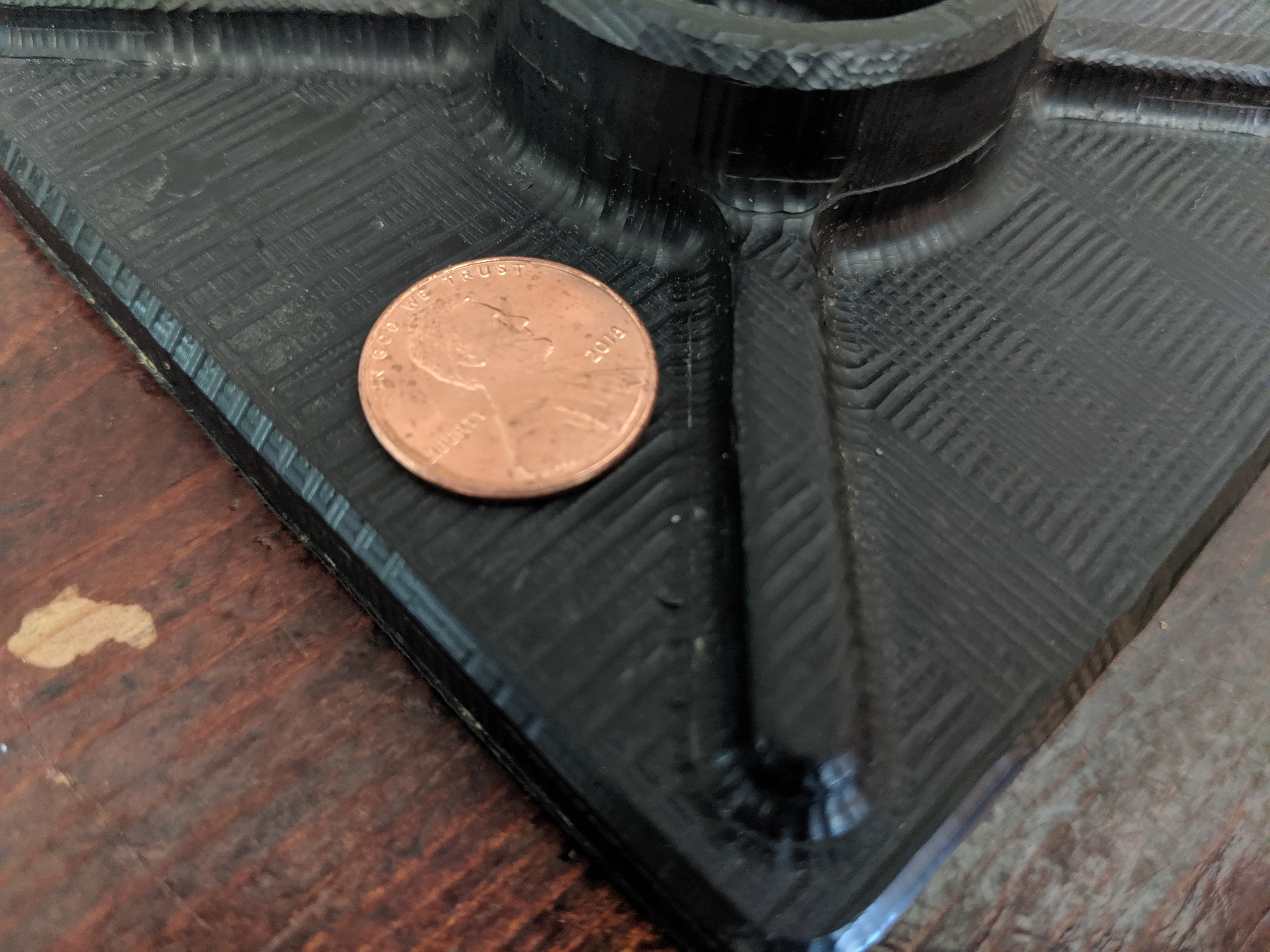
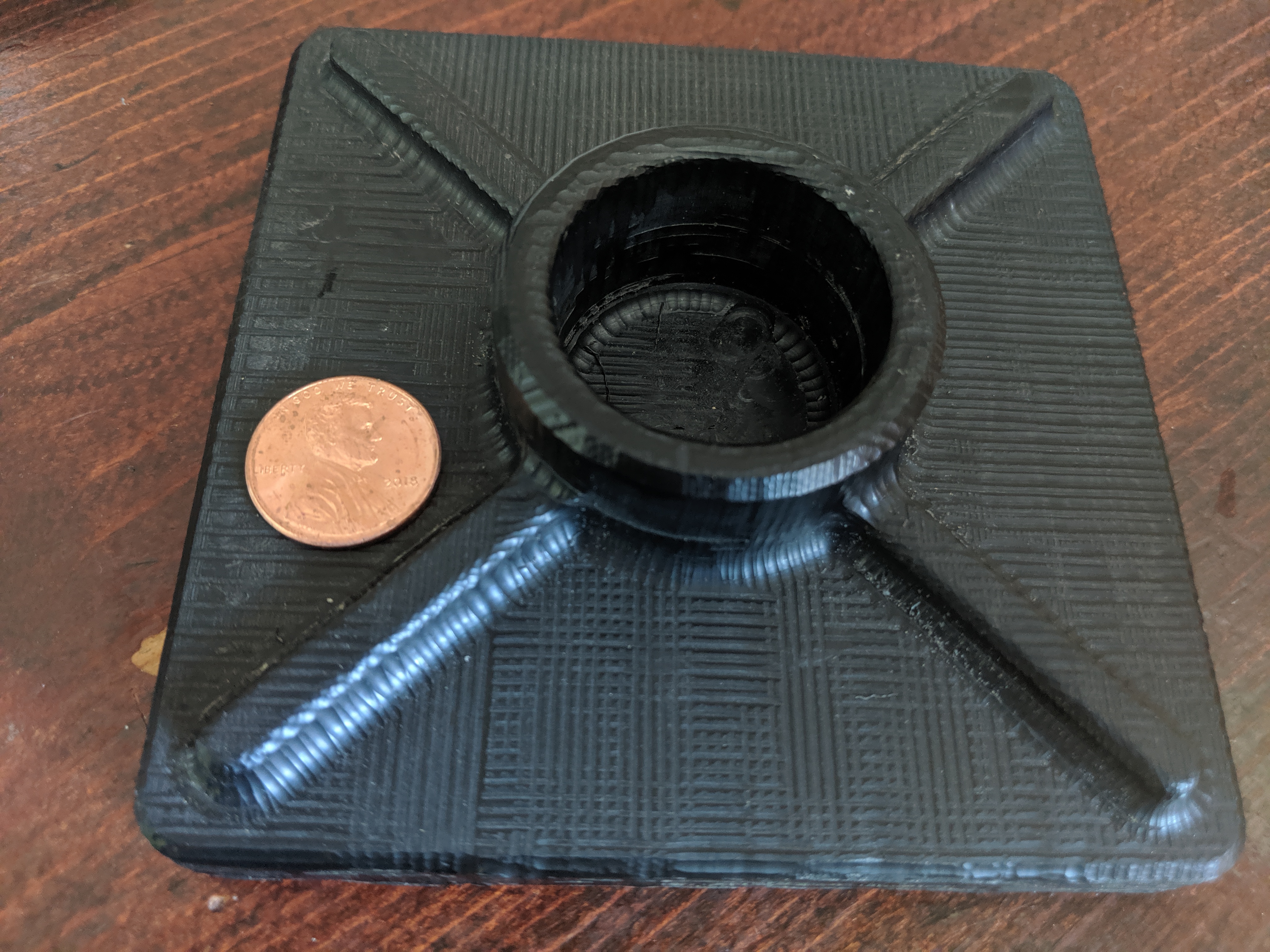
I finally had a need to carve out some more 3 dimensional parts and decided to give it a try using mesh cam and my S3. The material is ABS. I used 2 finish passes after roughing with a 1/8 ball. I can’t say I’m very impressed with my surface finish on this part and I’m not sure the cause. It seems as if I have various Z depth cuts happening as well. I wasn’t sure if my expectations are off, or if maybe I have slop in my components that is becoming apparent. Any thoughts?
2 Likes
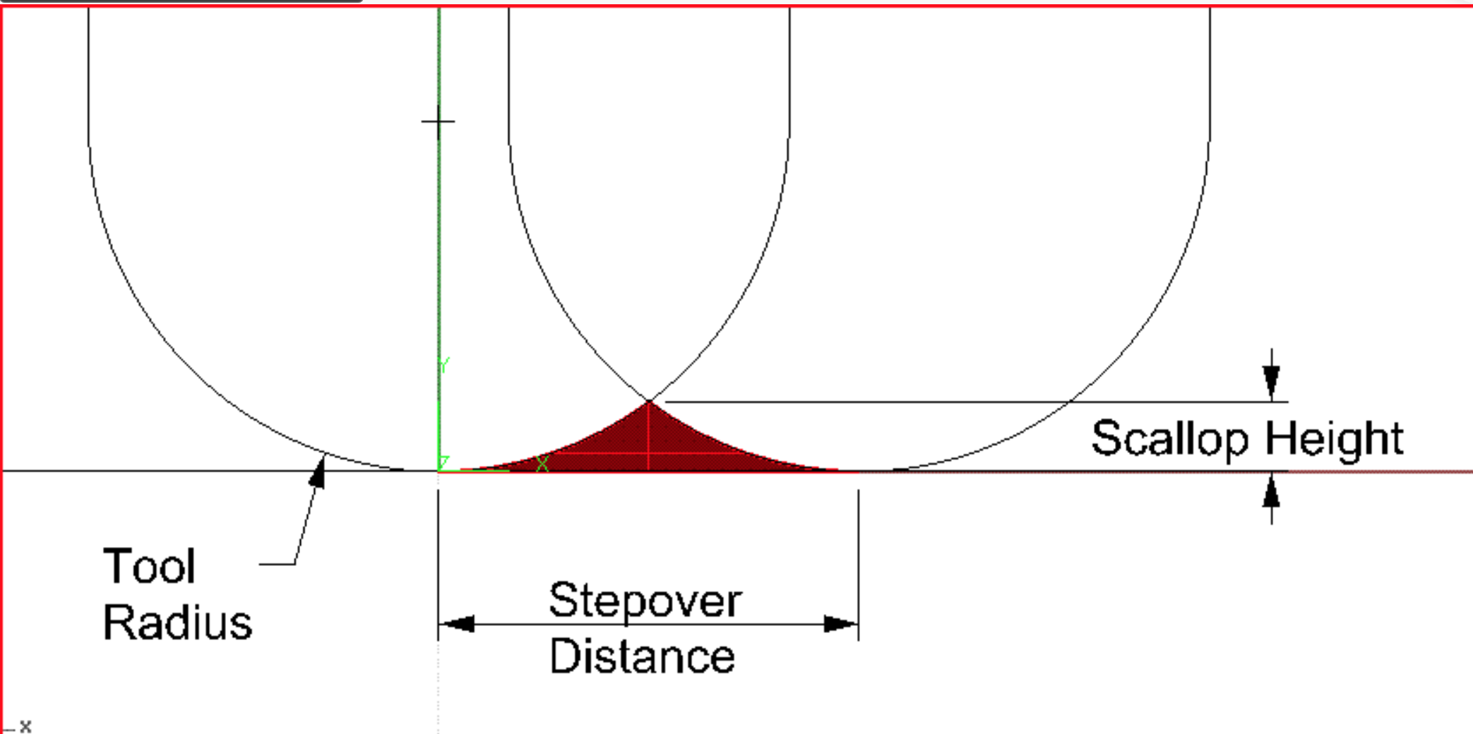
My thought are that you are not well versed on 3D cutting (sorry). Let’s talk about Ball End Mills. They should only be used in areas where you can’t use a Flat End Mill (e.g. Curved/angled and rounded surfaces). When finishing with a Ball End Mill you need to worry about the cusp (or scallop) height, and that is controlled by the size of the end mill, the nose radius and the step-over. I will use a step over as small as 0.001" to as large as 0.010" but doing so takes a LOT of time (which is why you try to only use the ball end mill in areas that you really need to. Additionally, there is a sacrifice for time and that is bad surface finish.
So my recommendation is to use a large flat end mill where ever you can, a small flat end mill is the other areas and finally, use the largest ball end mill to machine the other areas as needed.
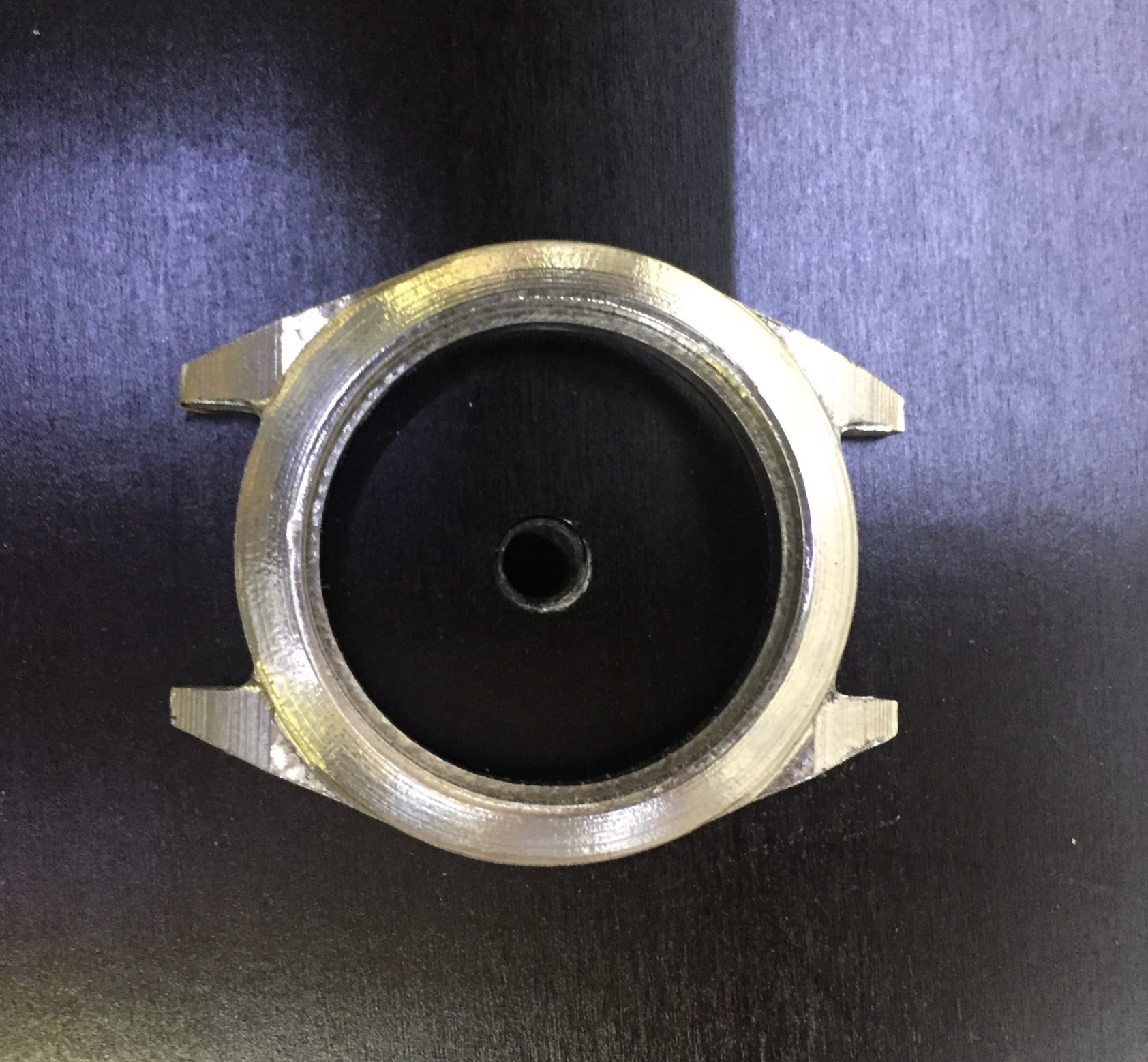
Here is an example of some stainless steel I cut on my Shapeoko usinf a 1/32 ball end mill with a 0.003 step-over (Before and after polishing.)
5 Likes
Thanks Rich,
So I certainly understand scalloping. I though I had mitigated that with a small step over. And agree that using a flat end mill would have been better in the larger flat areas. That said I didn’t see that I was getting very consistent and nice results in fillets and curved surfaces where a ball end makes since. Also I was concerned with what appeared to be inconsistent Z depths and some odd cut marks along the XY. I’ve seen examples of beautiful parts like yours so I know it’s possible. I just wasn’t sure if I had hardware slop or other issue to troubleshoot.
Before addressing the Z problems, how about correctly programming the part, and running it again.
Remember at the center of a Ball End Mill, Rad=0, so the SFM also equals = 0 so things don’t work well…and this could be 99% of your problem.
1 Like
with the 3D stuff in CCPro I first started out with “oh lets try the ball nose bit, that is what I got it for”… with similar mixed results.
but for one design I decided to just use my favorite small bit (a flat 2mm downcut) and it worked awesome. my design, like yours, had lots of flat and 90 degree angles and I did 2 passes at 90 degrees of eachother but square to the angles in the design… and the results were actually very good… better than ballnose
1 Like
Yah, I’ll try another pass at this and see how things look. Still getting the hang of the programming side of things. Thanks for the feedback.
Thanks for the comments fenrus. Lots more to try.
@borhaaa what software are you using to create your 3d toolpaths? Carbide Create, Fusion 360 and vectric software all play a little differently when trying to get a good 3d finish - though the principle is still the same.
If you upload your file maybe a few other members can show you how they would do the toolpaths? A lot of people here have been through the same situation.
On the mechanical side, I check all the simple stuff at the start of day that I use the machine - check belt tension, check eccentric nuts on v wheels are correctly tensioned, confirm no stepper pulleys are slipping, I also turn the machine on to lock the steppers, then grab the spindle and give it a solid push in every direction, including z+ and z- this will usually show up any issues.
At the end of each day or between jobs as required I give the v wheels and rails a clean with a toothbrush to keep them shiny
Another thing that may have a negative effect on your surface finish is tramming. Check that your spindle is perpendicular to your wasteboard in X and Y.
1 Like
Thanks Stuart,
I was using MeshCam to generate my tool paths. 1/4" endmill roughing, 1/4" ball for both finishing paths.
I’ll double check the Z and give it a shove. I realized I did have some aluminum shavings that appear to be ground into the V wheels from several previous runs. That can’t be helpful. I need to figure out a good way to keep that from happening.
here is the file
ryanfoot 7_19.STL (504.6 KB)
1 Like
thanks Luc,
It was level at one point but I’ll double check that too. Appreciate it.
Just to follow up. When locked I found quite a bit of wiggle on the router. Loose eccentric nuts. Dumb. Anyway time to give it another shot. Thanks again.
4 Likes
Good that you found something that could be the culprit… let us know how you go
There is plenty of documentation around, but I usually tighten my eccentric nuts until the point the V-wheel cannot be turned with my fingers. Also throw some threadlocker on them - will save you having to adjust them regularly
1 Like
This topic was automatically closed 30 days after the last reply. New replies are no longer allowed.