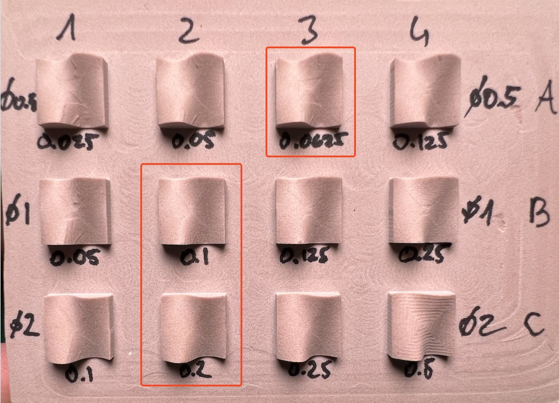
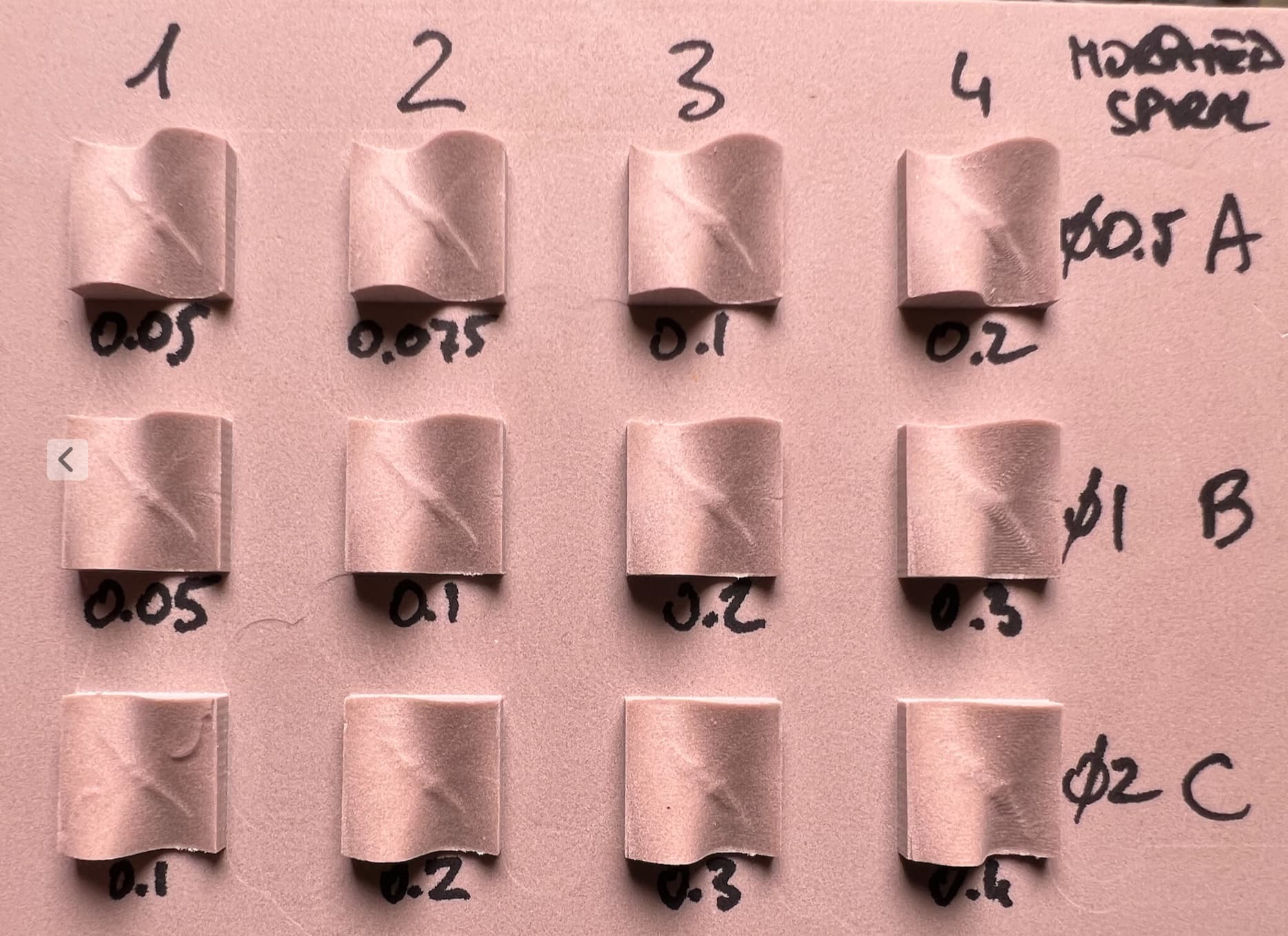
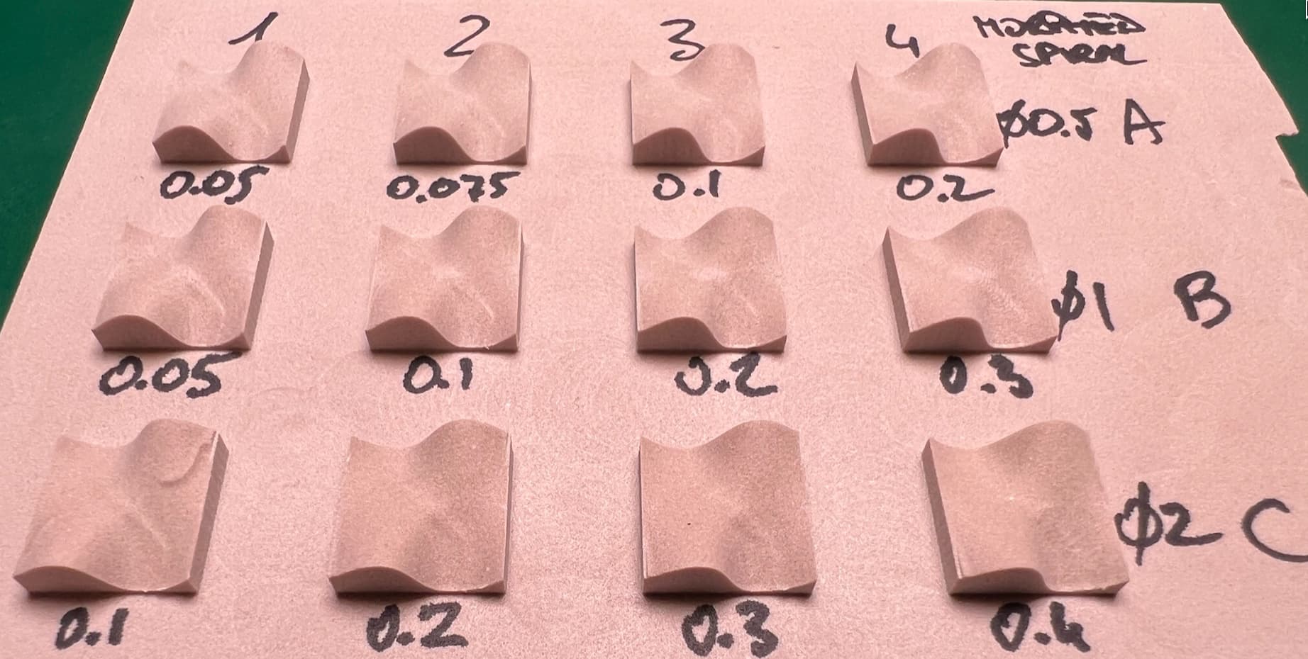
I wanted to know what are reasonable stepover values for various endmill sizes in a scallop toolpath, so I created a quick test piece. I did get my stepover values (marked in red on the first photo), but I was surprised to see artifacts on the surface. I do not understand what causes them, so I thought I’d ask for advice.
There are two kinds of artifacts:
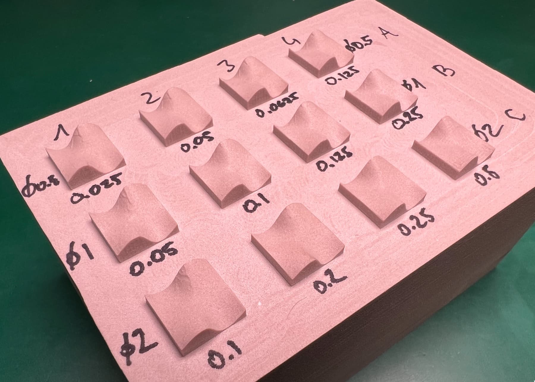
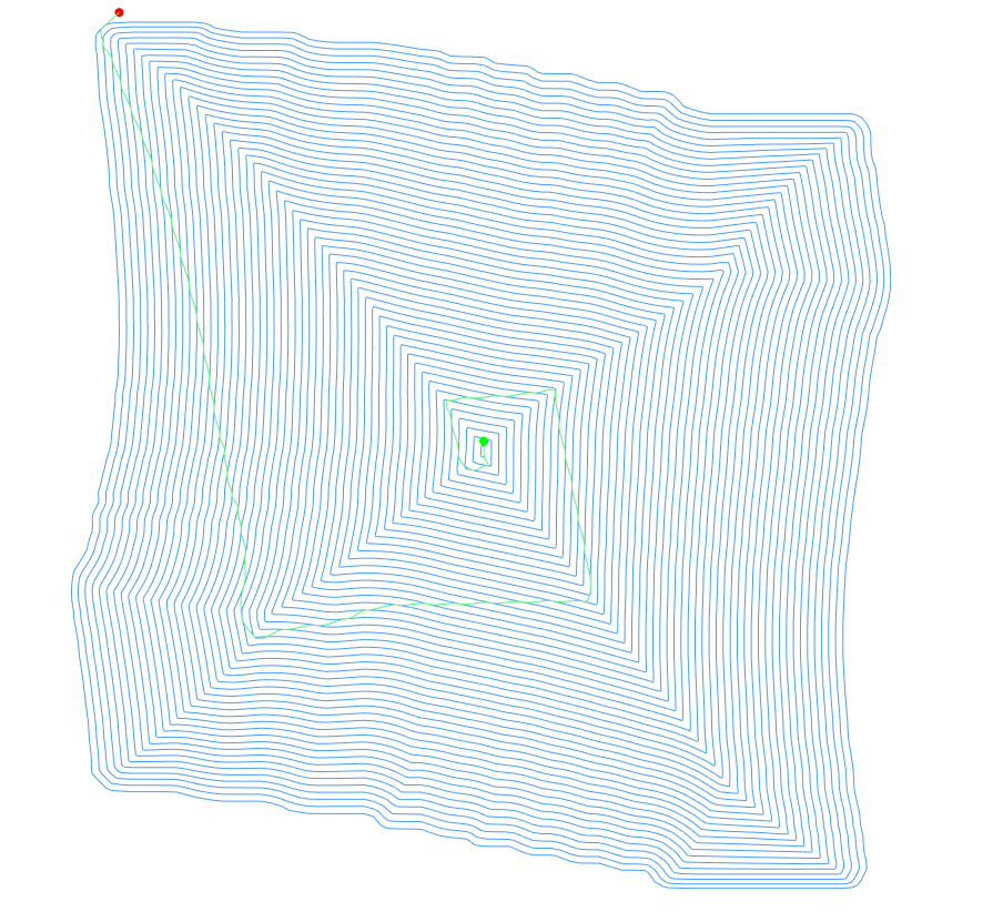
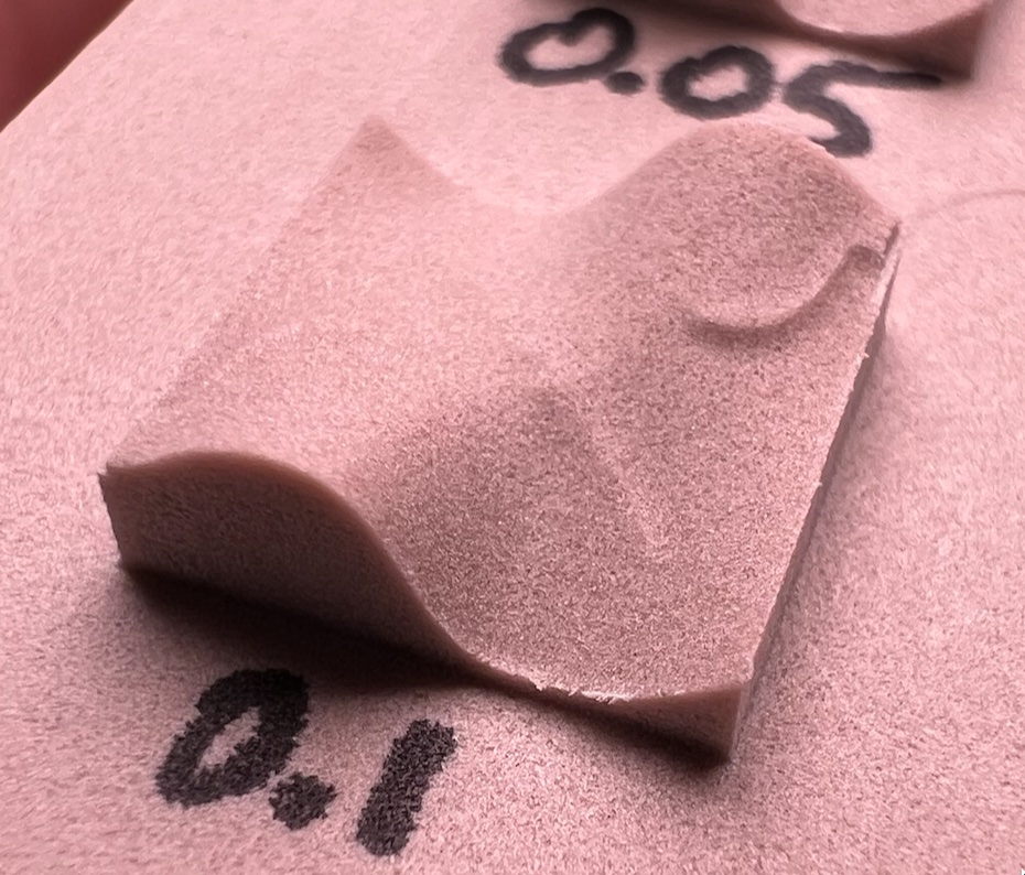
The hourglass shape seen when looking from the top (especially visible in A1 to A3 and B1).
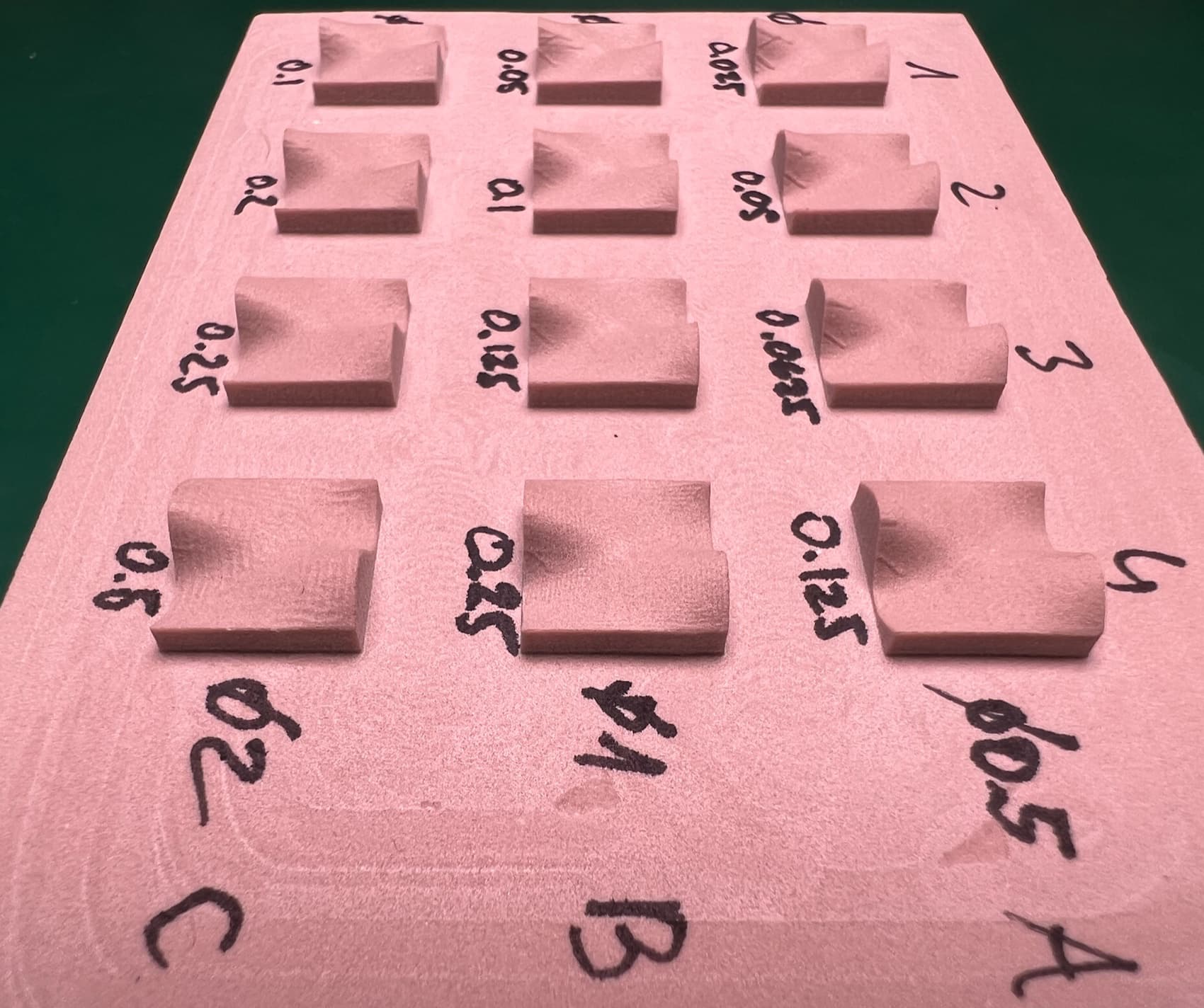
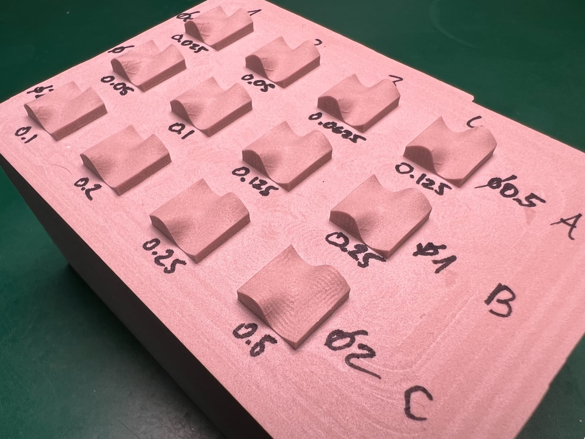
“Veins” on the steeper part of the slope, which are strangely not visible on every slope.
Jan,
I do not have Fusion 360 but it looks like you are using a constant step over value. Look for a setting that allows for you to step over based on scallop height. If Fusion 360 has this setting, set it to something like .0003".
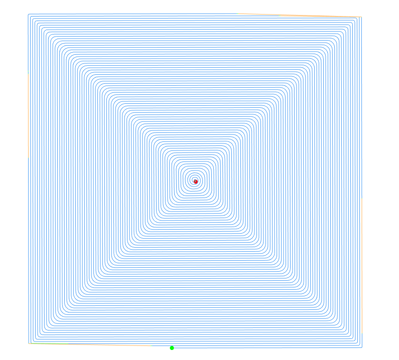
@jwr The hourglass artifact you’re seeing is due to the consistent 90deg turns in the toolpath. I would try a Morphed Spiral toolpath instead. Scallop operations sometimes end up with odd paths.
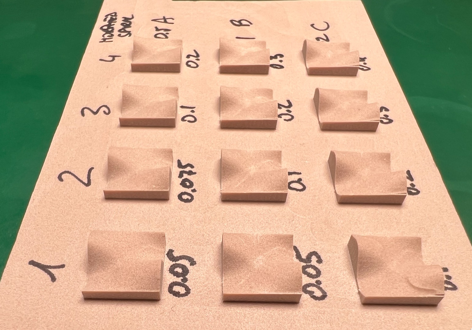
From straight above:
@neilferreri Thanks for the morphed spiral suggestion, that might indeed improve the finish, and I’ll try that.
As for the “veins”, I noticed that they occur only on descending slopes, never on ascending, which makes me suspect they have something to do with the mechanics of my Nomad 3’s Z axis. I did lubricate the rails and screws recently, though.
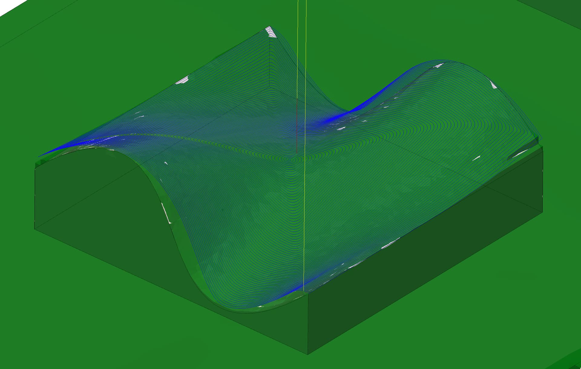
So. Did another experiment today, using only the morphed spiral toolpath (and slightly different stepover values to get a better feel for the usable range).
Turns out morphed spiral looks great on the computer screen, not so great when actually cutting. The results are actually worse than with scallop.
This is my go to finish pass. I can get smooth, functional results using two parallel passes at 90deg from each other.
I definitely think you’ll need two different finish operations on that part.
I’ll try that next — a combination of scallop + parallel and two parallel passes.
Just to explain, the problem is not theoretical: I’ve been milling keycaps, which have a gently curving top profile, and I got the hourglass on one, and a vein on another one.
To be more precise, I’ve been milling positive molds, which are then filled with RTV silicone to make negative molds which are used for polyurethane resin casting.
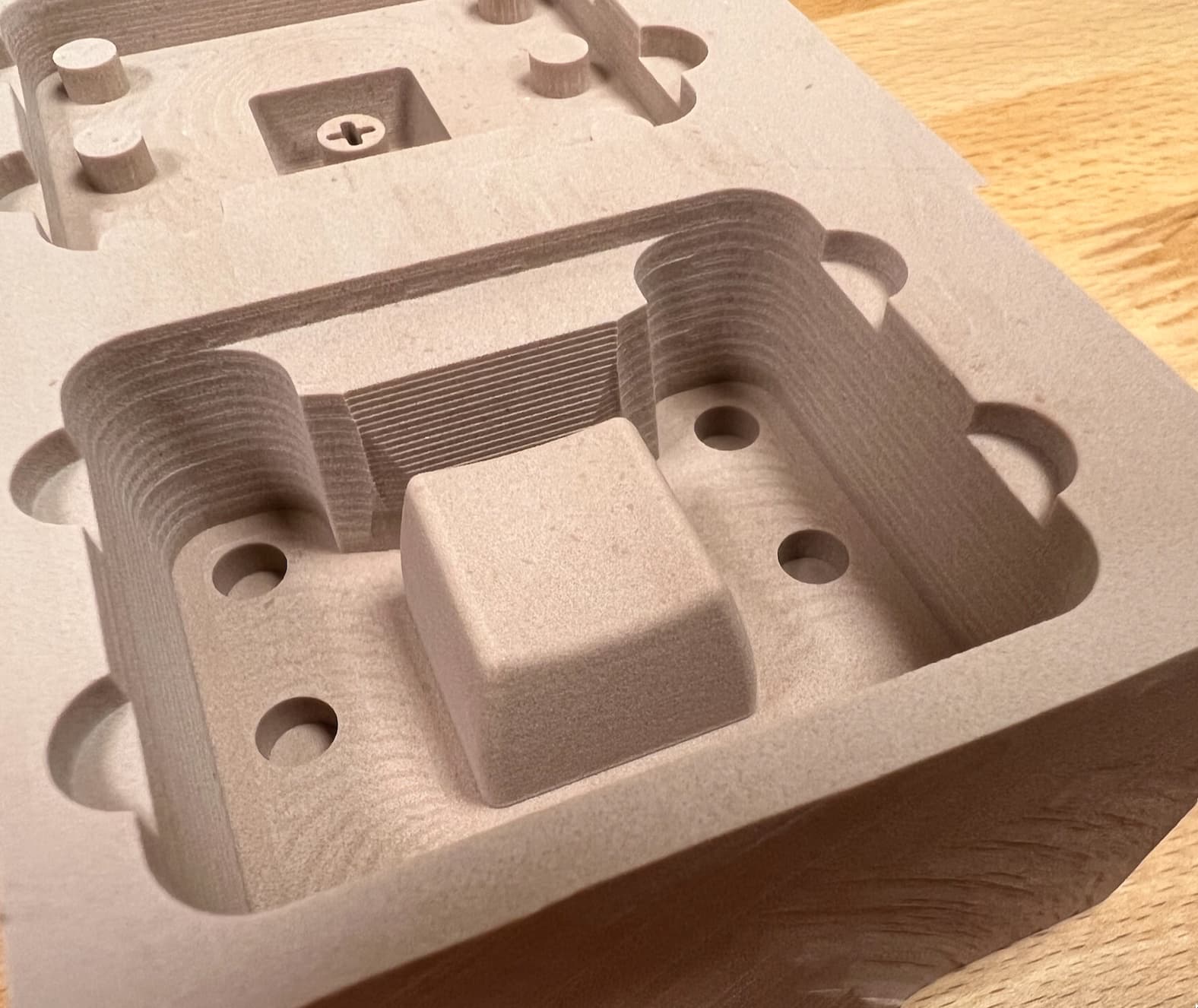
My conclusion, after testing various combinations of scallop, morphed spiral, and parallel passes, is that a combination of scallop and parallel is the way to go. Here is an example of what this produces (look at the top of the keycap):
This is with a 1mm endmill, 0.1mm stepover. The sides of the keycap require minor sanding, but the top is almost perfect.
I still don’t know where the “vein” artifacts come from, but I have my suspicions now, as I’ve just noticed that my Z motor sometimes moves slightly (reported to support and waiting for an answer).
One thing to note. When doing scalloped ball mill cuts, I try to use the largest ball mill that will fit into the part details. This allows a bigger stepover for a given scallop height, or using a much smaller scallop height without increasing the cut time to something unreasonable. The larger tools are also more rigid & stable so result in better finishes.
Yes, I had the same thought — but I need to figure out how to split the toolpath into two (perhaps by height), as there is a narrow valley behind the keycap where a 2mm endmill doesn’t fit. For the rest of this project, a 2mm or even 3mm ball endmill would work just fine (and likely better, as @Tod1d said!).
Outlines in sketches to use as your Machining Boundary, then play with the ‘tool on boundary / inside boundary’ options.
1a) Go to “contact point boundary” mode
1b) Additional offset to put a little air gap in for safety
Avoid / Touch Surfaces and select the areas to avoid