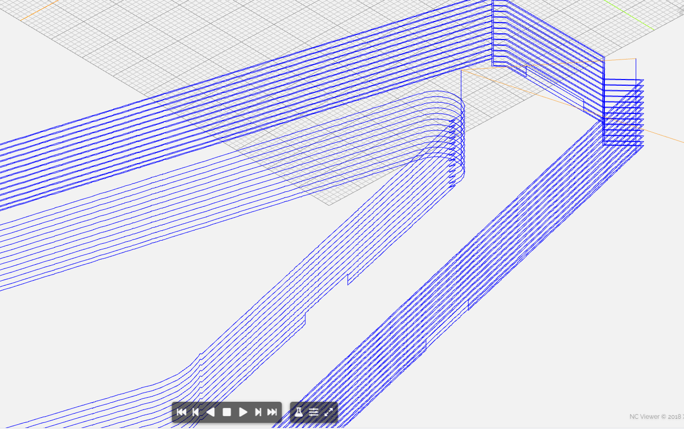
A simple push stick with contour tool paths and no offset to cut the inside and outside profiles.
I create 6 tabs and only the tabs on the inside profile are shown in the simulation using Carbide Create and Camotics.
I have not tried cutting it on the physical machine.
Why am I missing the tabs on the outside profile? Here are the c2d and nc files.
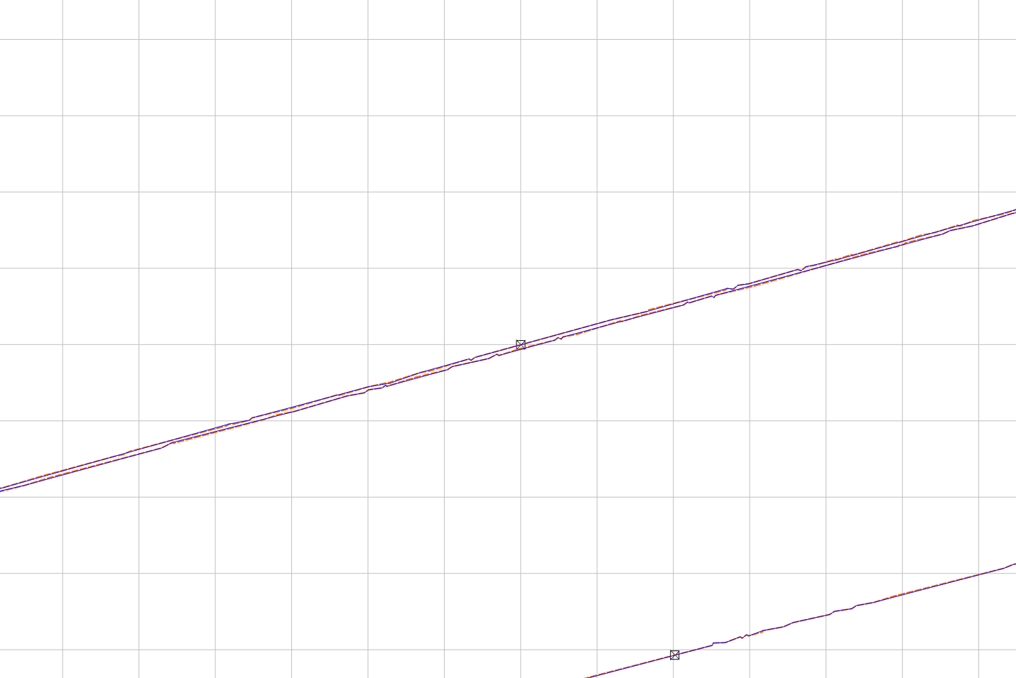
Thanks for the reminder to ZOOM in on the design. I used the bit map trace function to create the image from a scanned printout of the push stick. The bit map did something. A manual trace of the outline will probably take care of the ‘funky’ lines.
You should be able to tune the tracing settings (threshold) to avoid that, and clean-up the rest of the vector too.
Sorry for the “funky” language, sometimes I can’t quite remember what’s the right word for a given thing, so I use something I think is close enough to still be understood by you native speakers
I resorted to old technology. I traced over the printed document with an ink pen then re-scanned it. The open contour was closed and the tabs worked correctly.
Alternately, you could have drawn in a small rectangle over the gap and Boolean unioned which would have made the path into to separate paths and deleted the unneeded one.
As usual Will Adams solution was the simplest and most elegant.
Whether using my low tech (ink pen and scanner), node editing, Jeff’s trace or Will’s solution required first identifying the issue.
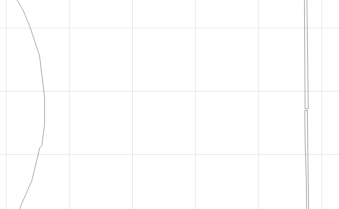
Carbide Create identifies open vectors by color but not open contours. That requires operator attentiveness. And this operator has now learned this lesson. There were indicators which I missed. Including noting the path Camotics displayed when running the simulation - it ran to the end of the line in one direction then completed the line in the other direction.
The thing is, this is a closed path — it’s just not topologically closing the area which is expected — I guess a check on this in Carbide Create would be to try to assign a pocket Toolpath — was it traced in Carbide Create? What did the preview there show?
“it’s just not topologically closing the area which is expected”
Concisely stated -
The design was traced in Carbide Create.
In hindsight the preview did show the problem. I just didn’t recognize it.
I created the contour tool path using various offsets.
When choosing no offset the preview showed correct because the gap between the ends was less than the diameter of the bit.
When choosing inside offset nothing was cut because the gap between the lines was less than the diameter of the bit.
When choosing outside offset the preview showed material being removed around the shape of the line. This should have been the red flag but I missed it.