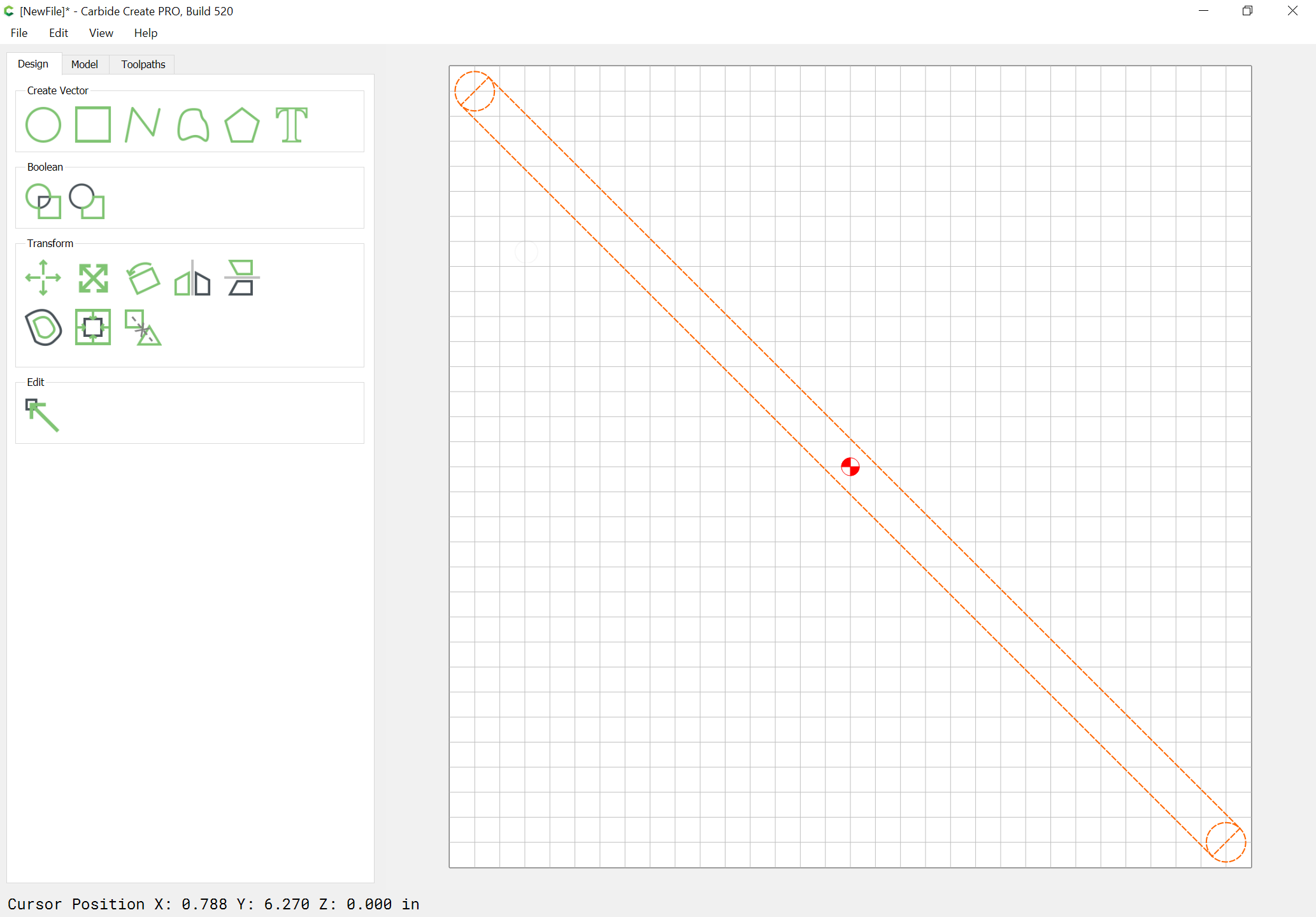
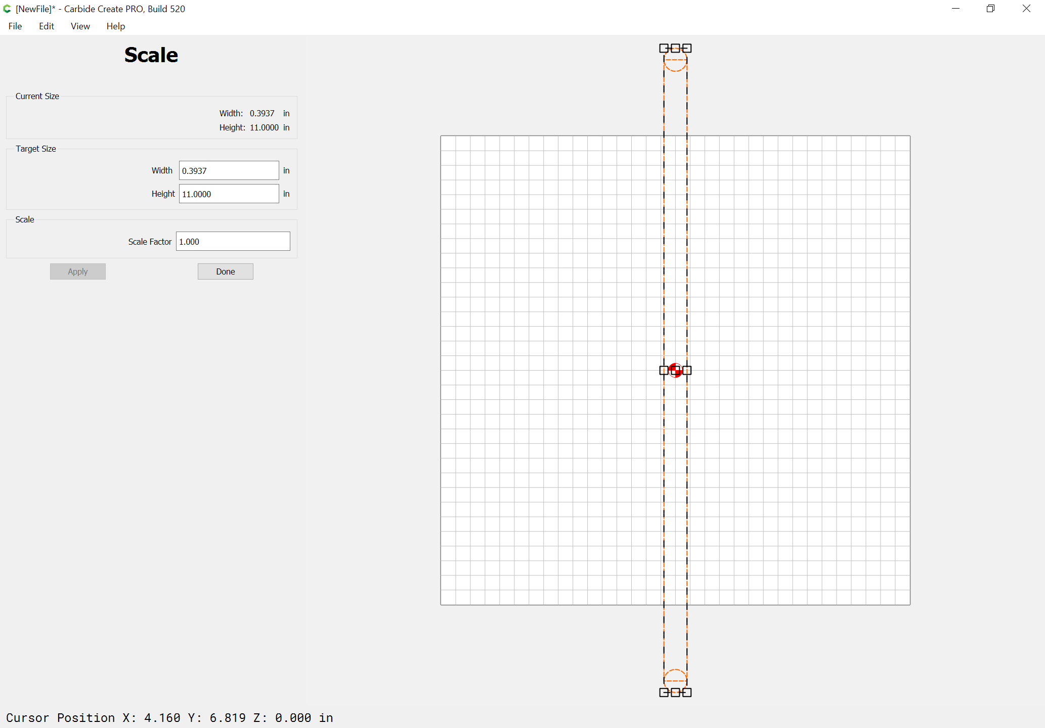
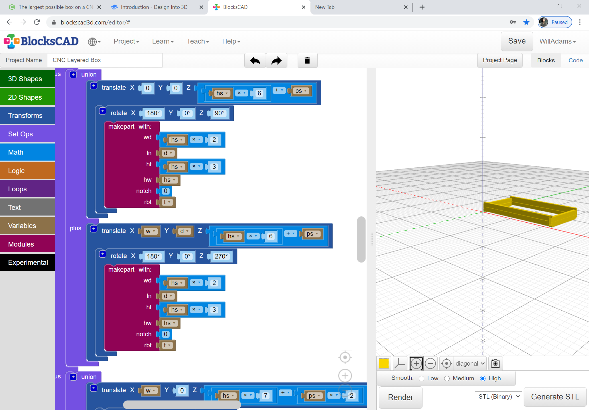
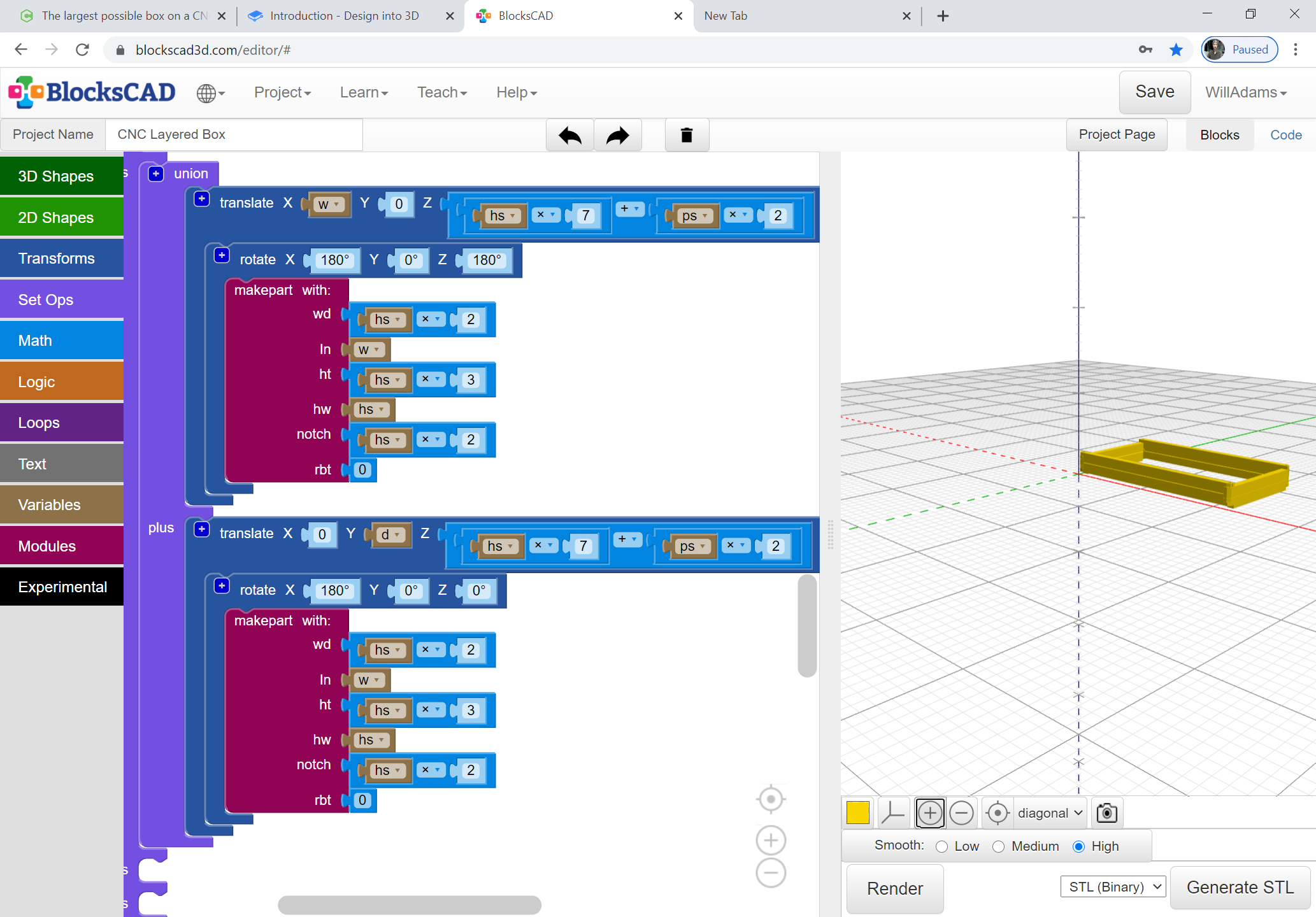
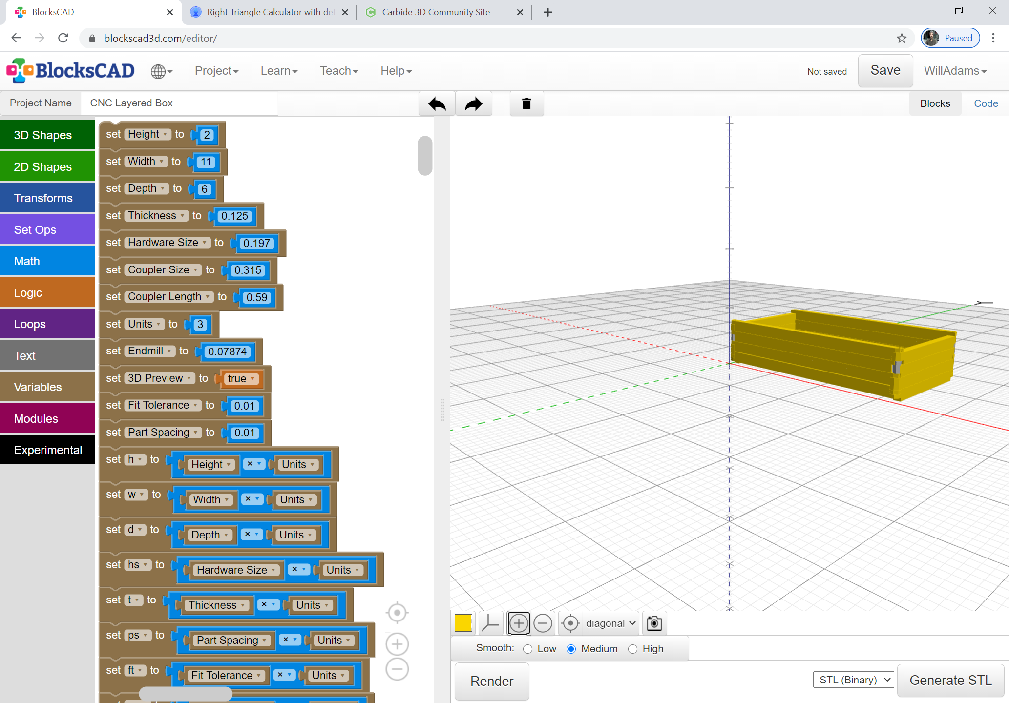
Ostensibly, a box on a CNC would be limited to the length of one or the other axis w/o resorting to tiling. It is possible to cut along a diagonal, so despite for example, a Nomad’s 8" x 8" bed, one can make a box which is 11" x 11":
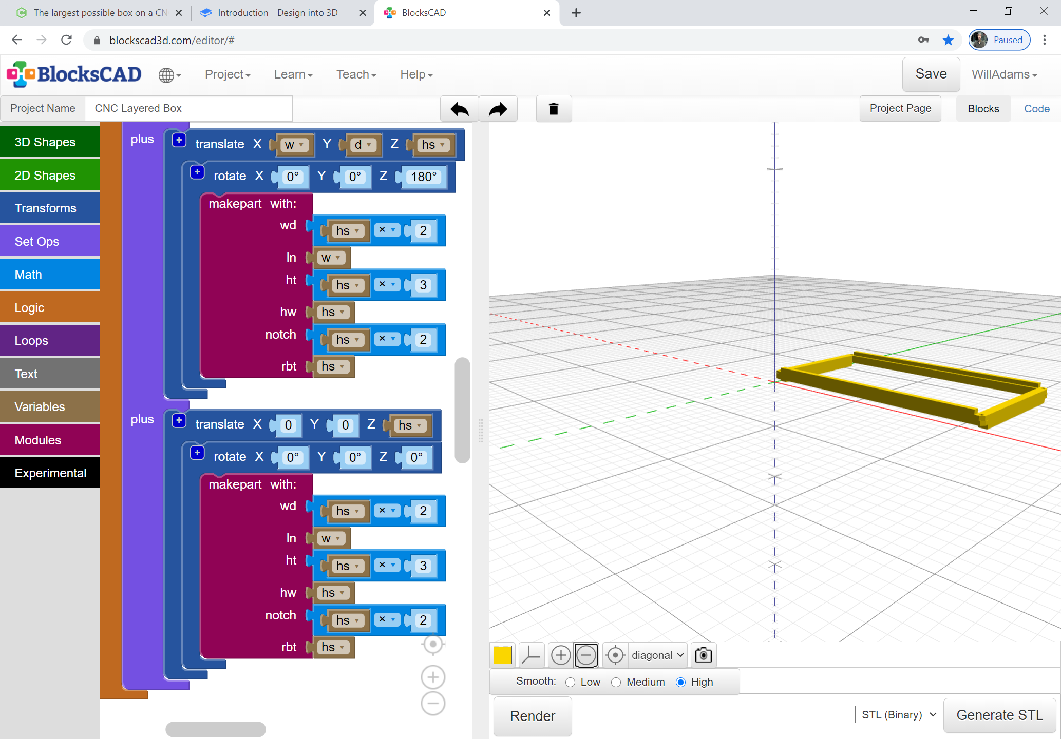
The parts of the box would be shaped so that each could be cut in a single setup, and assembled using a pair of low profile SHCSs and a coupling nut at each corner.
One thing to add and the box size should be determined by jogging to the extreme front left corner and setting X zero. Then jog to the extreme right and see your measurement and write it down. Then set Y zero and job to the extreme back right and write that number down. These are your maximum cutting box size. You could change your machine paramaters in the MDI interface to get slightly larger area but not much. The maximum amount of jog is set by configuration. If you jog to the back or front and power off the Shapeoko you can push the gantry further to the mechanical limit but setting that is dangerous because if you miscalculate the machine will hit its limit and lose zero by hitting the limit of the mechanics. You can come close but do not set the extreme maximum.
Will Adams posted these configuration settings a while back. These numbers are in MM.
To allow folks to confirm their Grbl configurations, here are the settings for:
Setting
Belt Drive Z-axis
Z-Plus (inc. Pro)
HDZ
$100
40
40
40
$101
40
40
40
$102
40
200
320
The Travel Dimensions for the various machine sizes and options are:
Machine size and Z-axis type
X
Y
Z
Shapeoko 3 Standard Belt Drive
420
430
100
Shapeoko 3 Standard Z-Plus
420
430
95
Shapeoko 3 Standard HDZ
420
430
140
Shapeoko XL Belt Drive
830
430
100
Shapeoko XL Z-Plus
830
430
95
Shapeoko XL HDZ
830
430
140
Shapeoko XXL Belt Drive
830
850
100
Shapeoko XXL Z-Plus
830
850
95
Shapeoko XXL HDZ
830
850
140
Shapeoko Pro XL
870
440
95
Shapeoko Pro XXL
870
850
95
You can go into the MDI interface and type “$$” and then go to the log and look at the specific settings for your machine. You can change the setting in the MDI by typing ( $130, $131, $132 – [X,Y,Z] Max travel, mm) /130=Number or /131=Number or /132=Number. Verify the settings by typing in the $$ again and check each 130, 131 and 132 setting. Then you can jog again to the front left corner and set zero and jog to the extreme right front corner and write that number. Then set Y Zero and jog to the extreme right back corner and record your setting. Then jog to extreme left rear corner. If you do not get a loss of zero by exceeding maximum mechanical limits you are good to go. If you do then decrease the numbers for the axis that is having problem. Just to caution this is dangerous in a way because the limits have been set for a reason. The X can be increased because in recent configuration settings c3d reduces the X for accommodate dust control that is wider than your Z carriage like with a Suckit and other dust shoes.
When you send the configuration from CM the parameters will be set back to default.
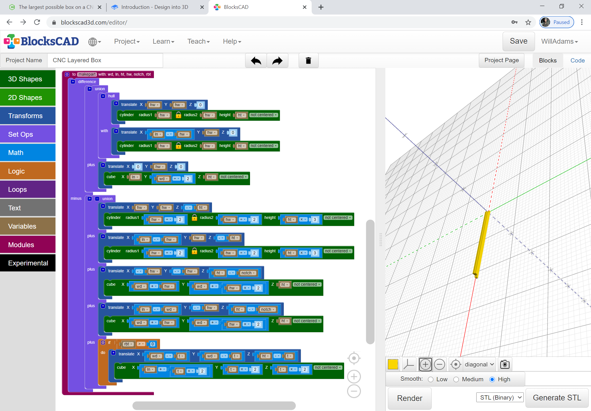
At the mid-point there will be a series of parts which will need the notch to be full height and hexagonal in shape so as to allow for the coupler, and adding a dowel for registration will likely be necessary to reinforce things.