For those that work in aluminum, thread milling would be heaven sent. That would mean a new cutter library catagory, and the ability to draw the tool cross section. If fusion can do it, so can carbide create. It would be like the holy grail of 2d cnc machining
This has been done before:
https://community.carbide3d.com/search?q=thread%20milling
perhaps it could be worked up as a “Quick Action”?
If you’ll provide an example of a tool and feeds and speeds for it and a hole diameter and thread specification I should be able to work up the G-code for that as a proof of concept.
1 Like
For the current project the thread is m6 sti (screw threaded insert or helicoil) the hole size is 6.23mm. The tool is a single form m6 threadmill.
The material is cast aluminum 19.05mm thick.
Do you think threadmilling can be done with the current carbide create pro ?
Hey Will…that link turns up: 50+ results for thread milling - was there one or two of those that you particularly think would shed light on how to do it?
No, Carbide Create Pro can’t do thread-milling — the 3D preview can’t show undercuts, and there isn’t a toolpath option for moving in an arc and down at the same time.
Link to a “Single Form M6 threadmill”?
My plan is to write the G-code by hand and preview it using a side project I’ve been working on — then it should be possible to use it by:
- probing the hole and the surface to establish zero (put the BitZero on the stock upside down to probe the hole, right-side up for the surface in a separate operation)
- loading the tool (it will be measured by the BitSetter)
- running the Quick Action (maybe the tool change will be included as part of that)
Perhaps if this works it could be added as a toolpath option in Carbide Create — I’m sure @robgrz could knock it out much faster than I, so long as we forgo the 3D preview as is currently done for Keyhole Toolpaths.
***This post has been editted i have added a photo showing a correct thread mill. ***
Thread milling is new to me, but all the examples ive seen the bit goes to center hole, plunges to depth then spiral cuts the thread moving up until it clears the hole.

Please provide a link to the tool which you are considering buying which includes all the details of the geometry, as well as your rough estimate on initial feeds and speeds to use and we’ll try to put this together this evening.
1 Like
M6X1.0 D4.85X20XD6X60X4T SINGLE PITCH THREAD MILL TiALN COATED For 60 Degrees
For machining internal threads.
SINGLE PITCH THREAD MILL
Processing pitch range
M61.0,M60.5,M6*0.75
N012-56UNS,NO12-48UNS,1/4-40UNS1/4-36UNS,1/4-32UNEF,1/4-28UNF,1/4-27UNS.1/4-24UNS.
Threaded cutter 4.85mm in diameter.
Machining length20mm.
Shank diameter 6mm.
High performance solid carbide.
WALTER 5 axis grinding.
High-end surface plating finish.
Suitable for carbon steel, stainless steel, cast iron, heat treated steel. Alloy steels.
Let me see if i can find the specs for m6 sti and feeds and speeds for a single form m6 thread mill in alum
I’ll be following this thread (heh…) closely.
I’ve already got a Saunders Machine Works threaded table but I wouldn’t mind making another ![]()
Thats exactly what im doing, making plates for smw vises. Ive got one started, 24 holes out of a zillion, hand tapping them. Thread milling would certainly speed things up
1 Like
An actual product page for that is:
which unfortunately doesn’t have a DXF of the tool profile.
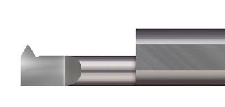
Going to McMaster-Carr for a similar tool:
we download the DXF and get:
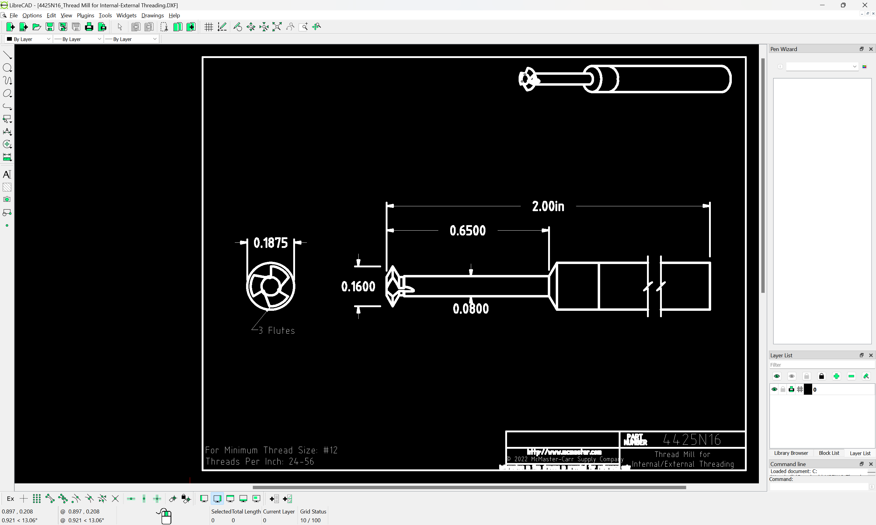
which is drawn up at 100% and seems the right size:
and gives a good idea of the geometry of such tooling and how to model it.
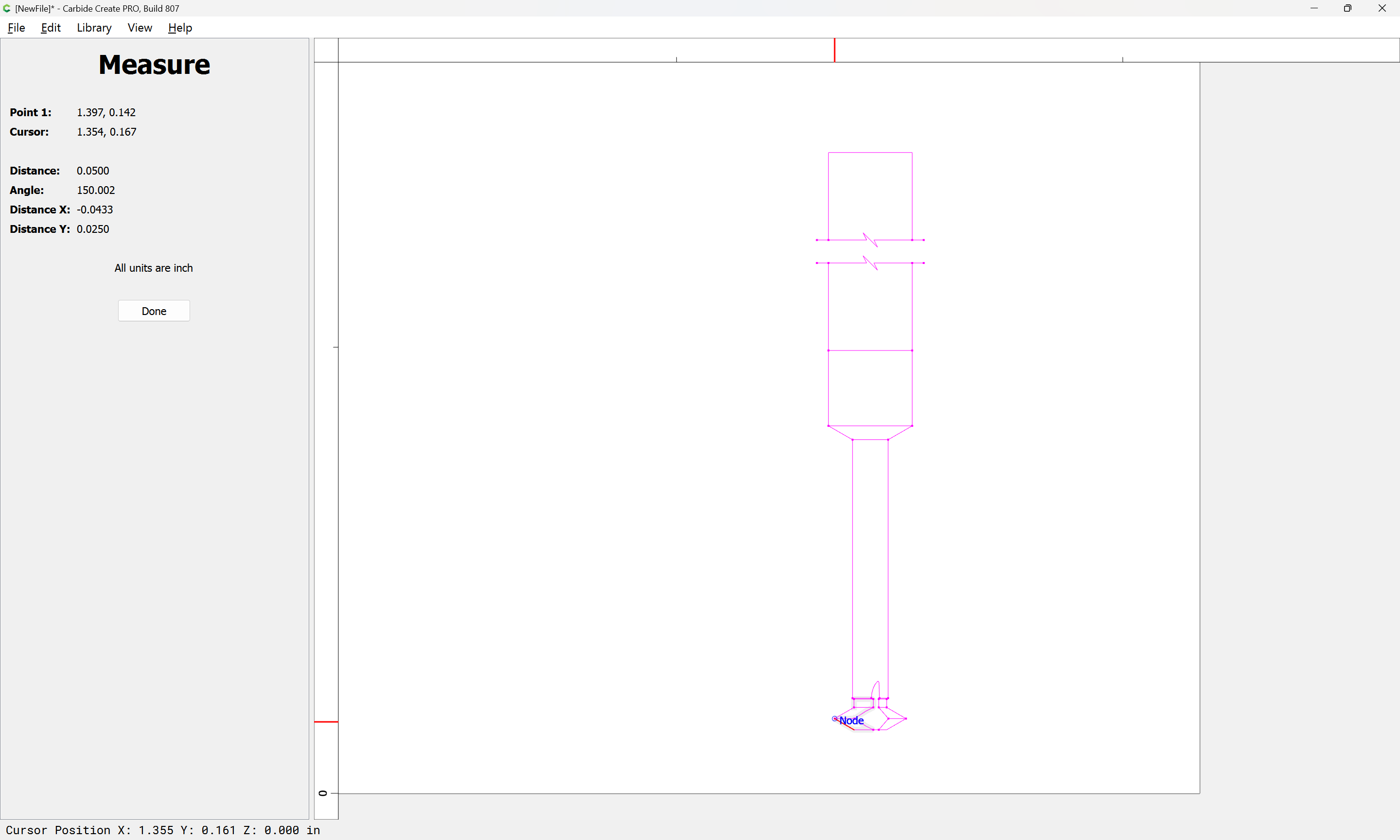
Working from the dimensions of the tool we model:
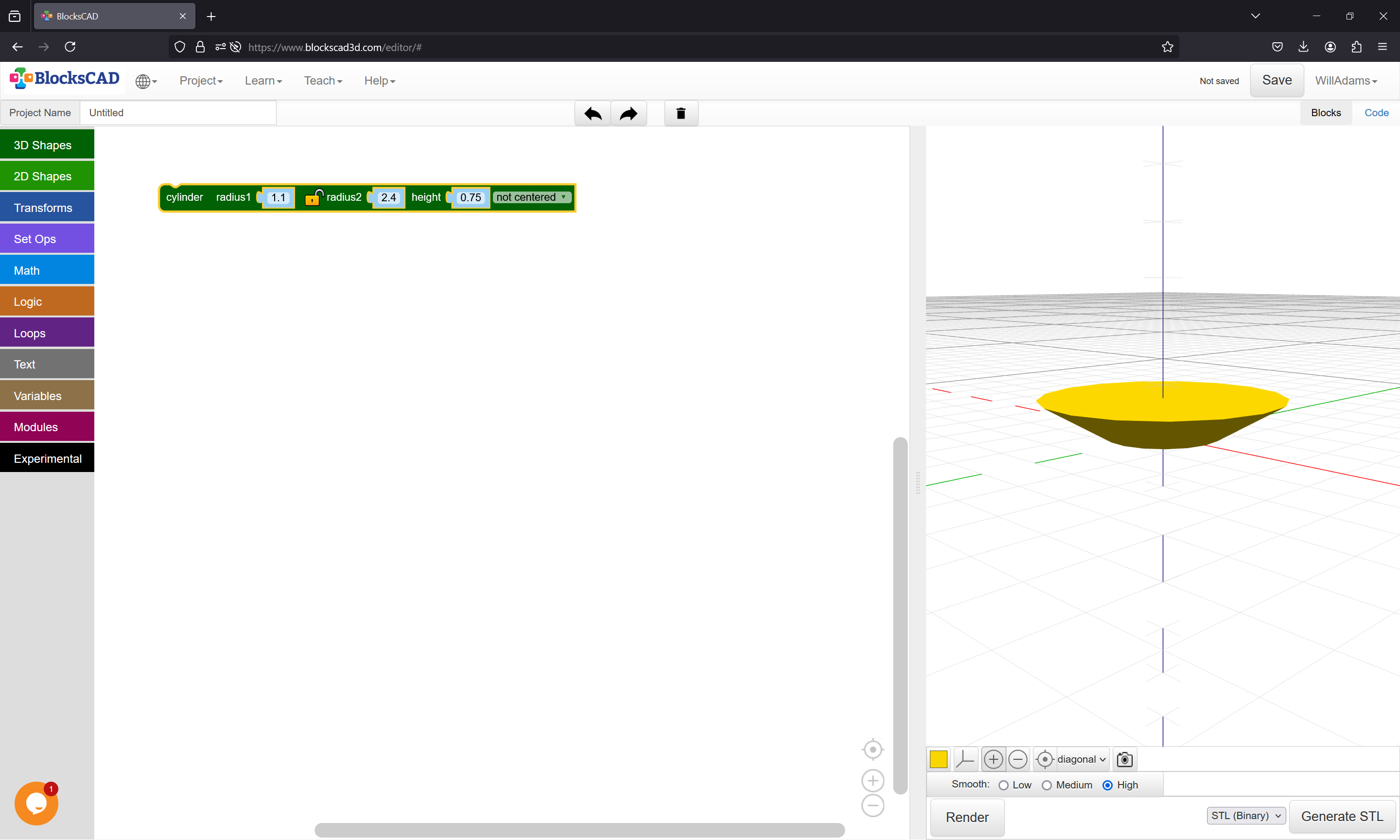
and:
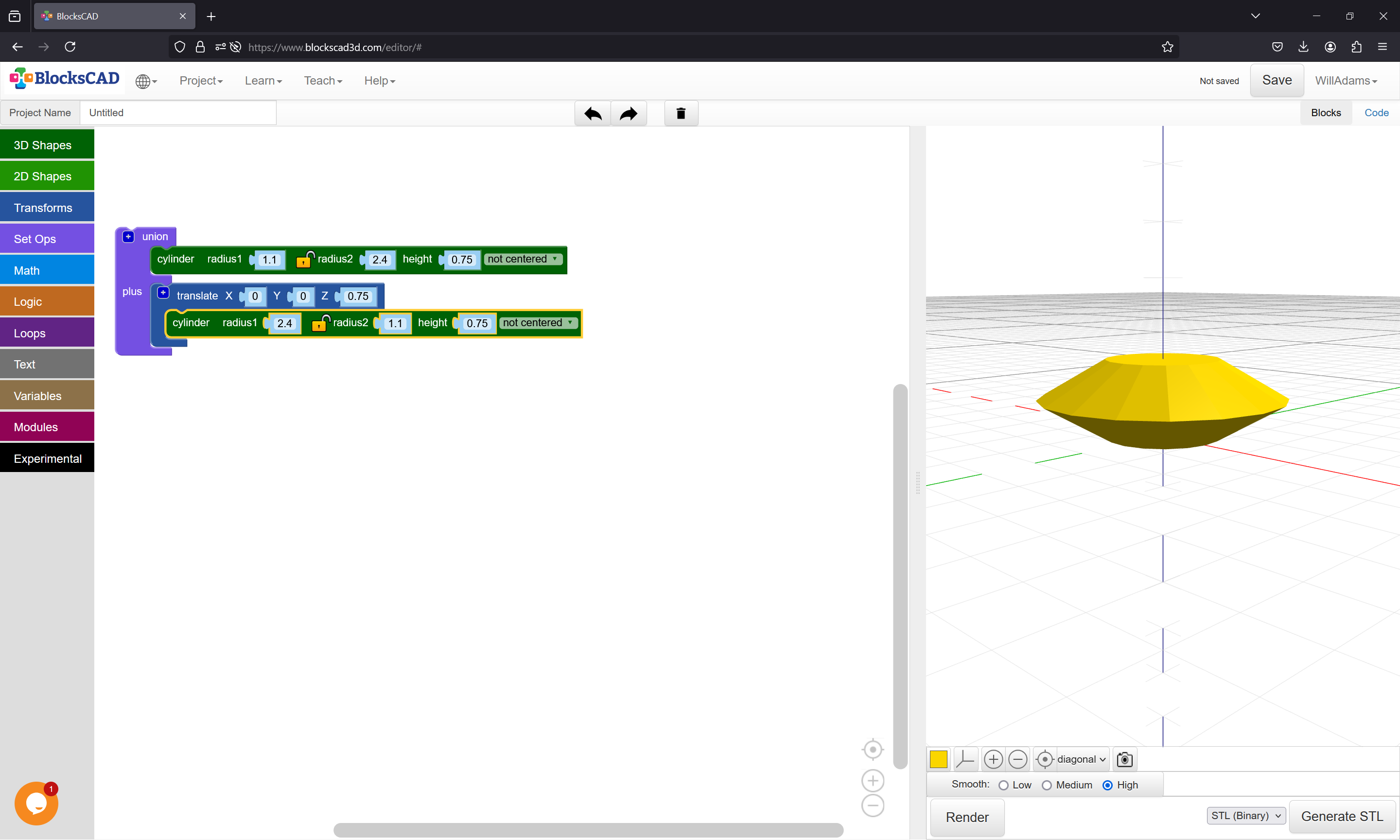
and add the shaft:
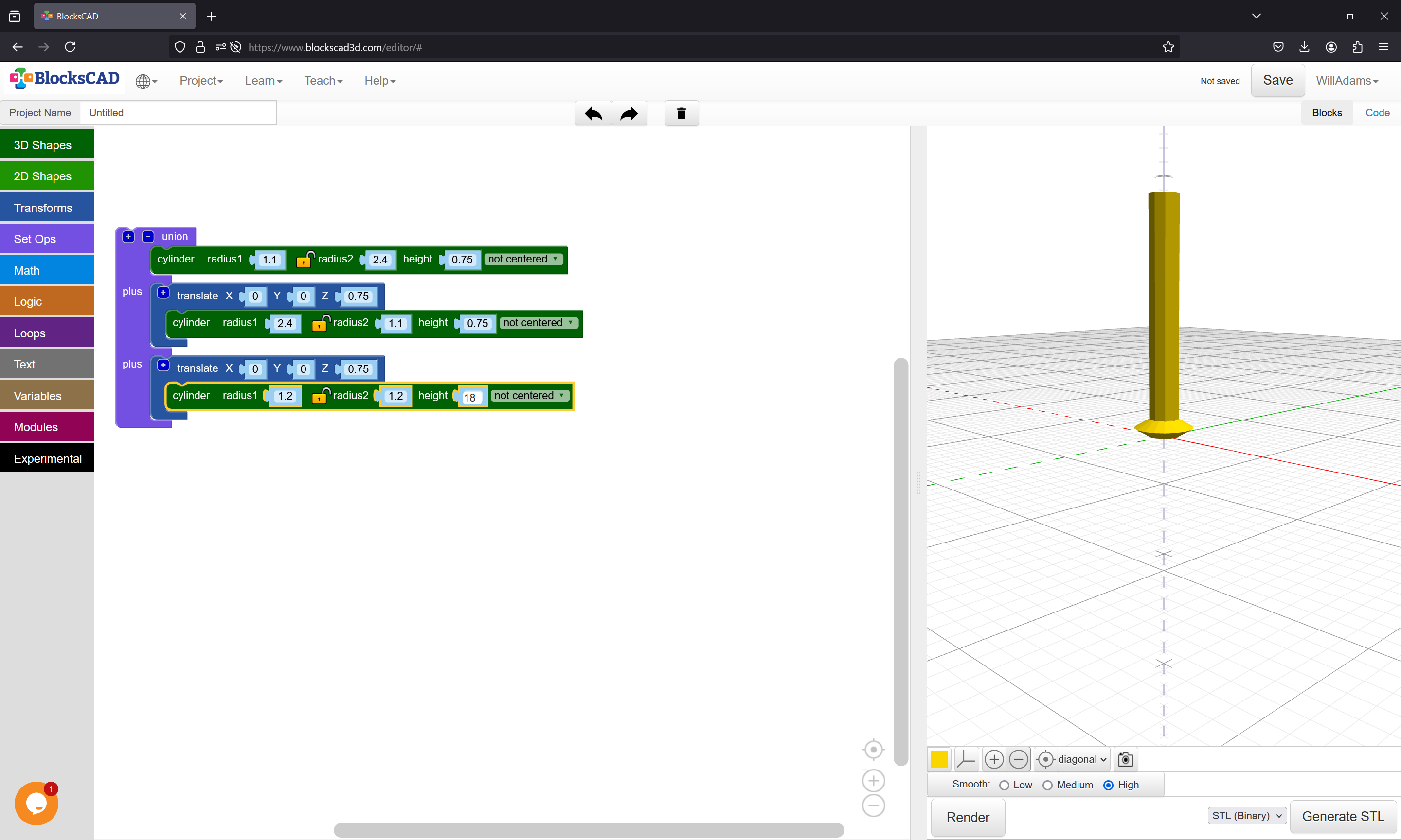
which gives us the code:
//!OpenSCAD

union(){
  cylinder(r1=1.1, r2=2.4, h=0.75, center=false);
  translate([0, 0, 0.75]){
    cylinder(r1=2.4, r2=1.1, h=0.75, center=false);
  }
  translate([0, 0, 0.75]){
    cylinder(r1=1.2, r2=1.2, h=18, center=false);
  }
}
which we then translate into Python and set up as a numbered tool in:
(Note that the above is a personal project, and has no tie to Carbide 3D beyond my using Carbide 3D tool #s where possible and noting that I work for Carbide 3D.)
1 Like
which is:
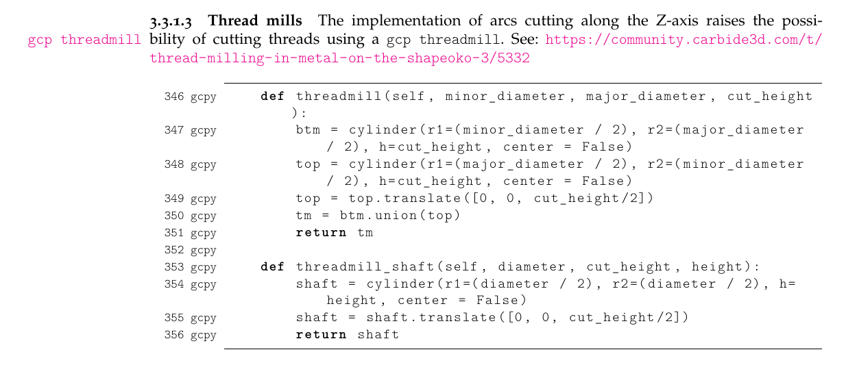
Then, the tool # is defined (we will use 648) and the code for the cut() command is modified to use the threadmill and threadmill_shaft commands.
    elif (self.currenttoolnumber() == 648):
        shaft = self.threadmill_shaft(2.4, 0.75, 18)
        shaftend = shaft
        shaftbegin = shaft.translate([self.xpos(), self.ypos(), self.zpos()])
        shaftpath = hull(shaftbegin, shaftend.translate([ex,ey,ez]))
        start = self.threadmill(2.4, 4.8, 0.75)
        end = start
        start = start.translate([self.xpos(), self.ypos(), self.zpos()])
        cutpath = hull(start, end.translate([ex,ey,ez]))
        toolpath = union(shaftpath, cutpath)
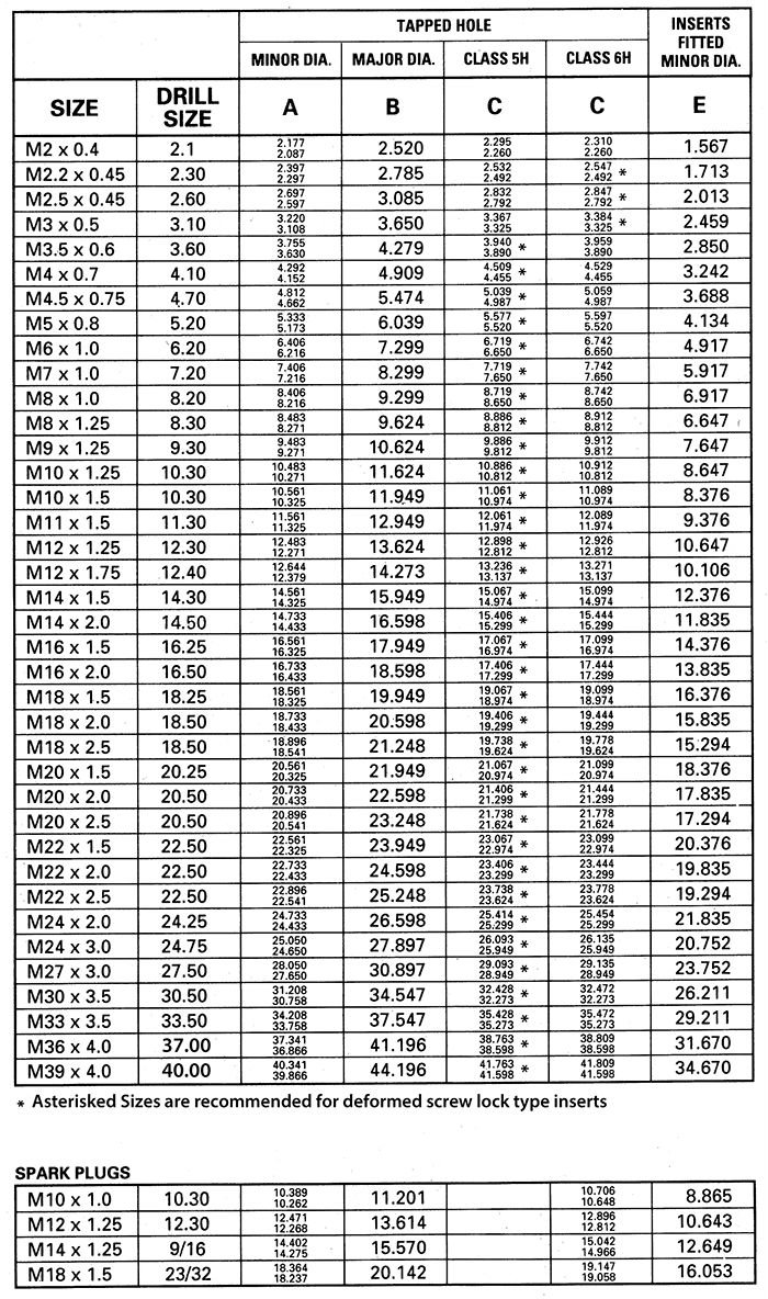
For M6x1mm the hole size is 5mm, so we start with the stock thickness of 19.05mm and put a hole through that at the center (we will directly model the hole, not create a toolpath for it).
First a huge thank you, that looks to me like it took some time and research. To this point ive only used tooling thats been part of a library. Ive done some modeling in solid works and C4D many years ago, but ive never seen a model represented as code. Ive got some studying to do before im able to understand everything you’ve shown. But now i have something to study and figure out how to do this on my own.
Again a huge thanks
The code as 3D model stuff is pretty specific to a program known as OpenSCAD:
though as shown above, I usually use:
https://www.blockscad3d.com/community/projects/1868708
It looks like the code worked:
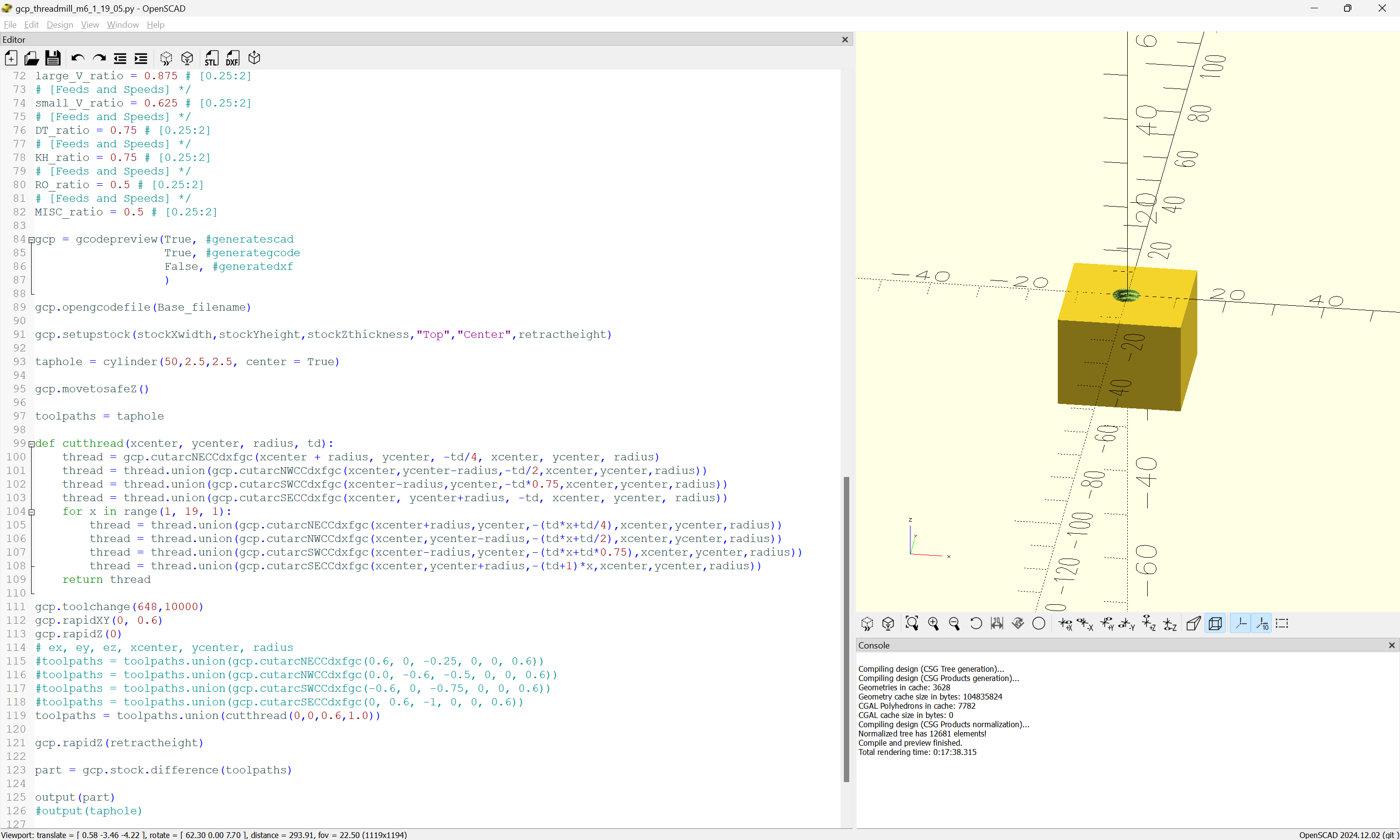
hang on while I pull out the G-code and test it.
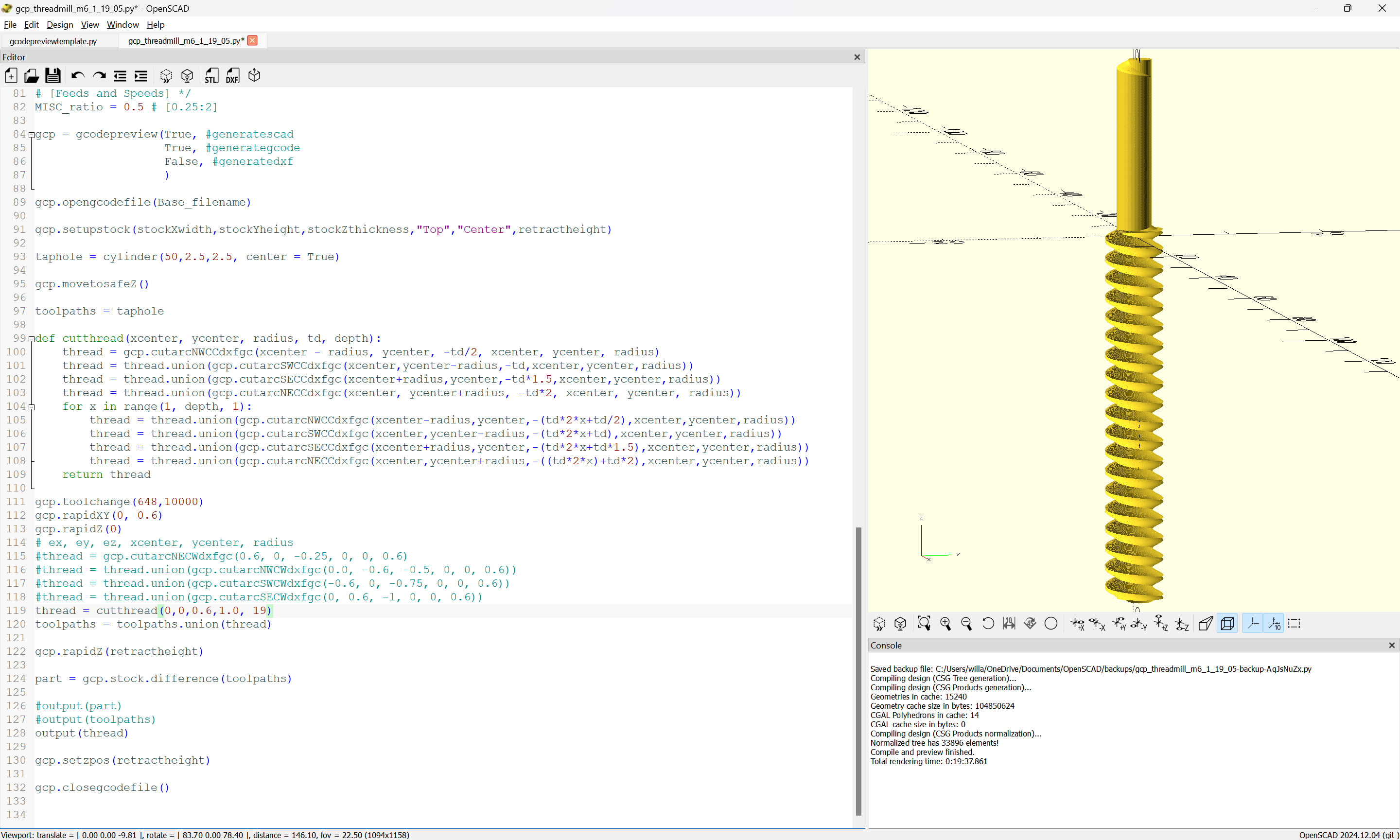
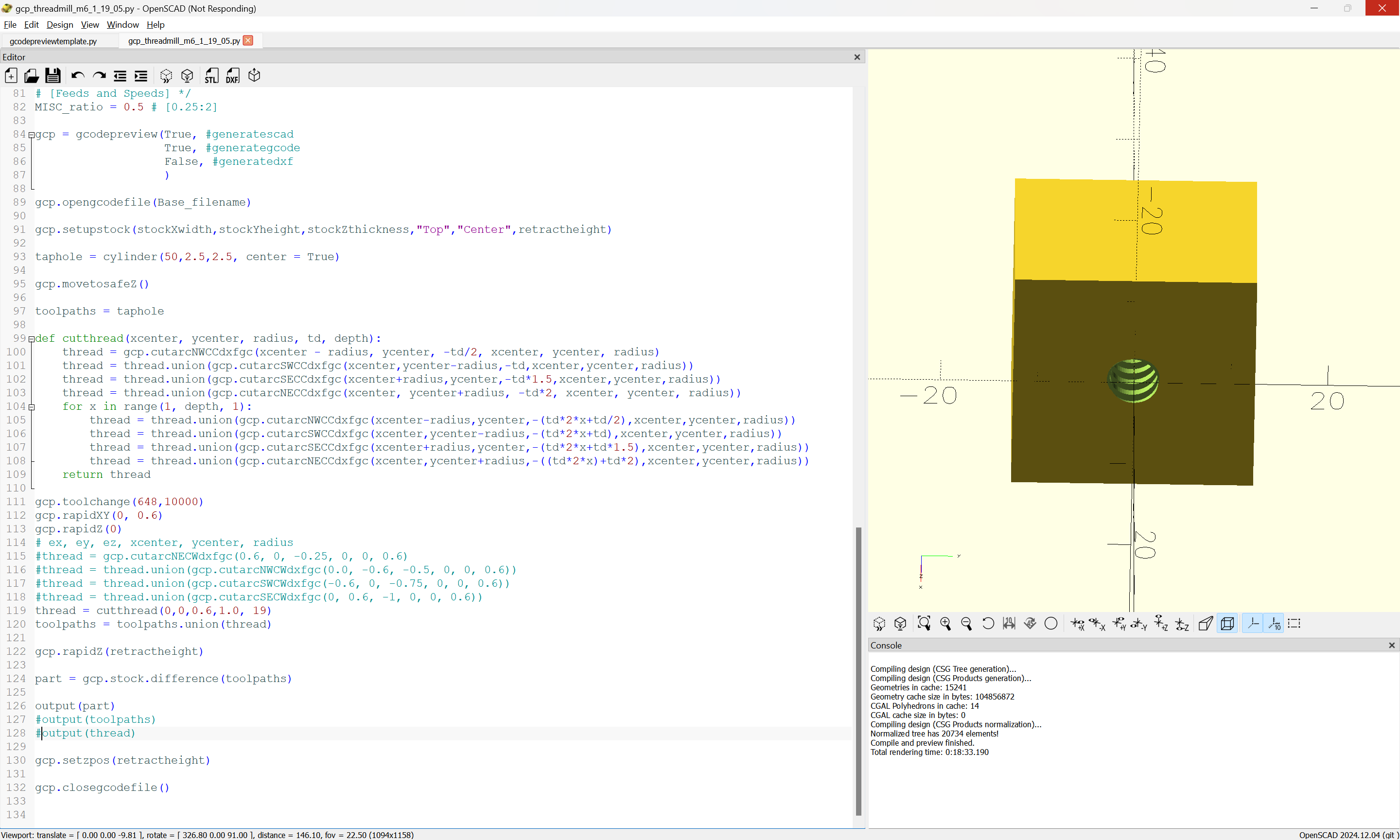
It looks as if it worked (once I fixed it):

(Design File: aexport)
(stockMin: -12.5, -12.5mm, -19.05mm)
(stockMax:12.5mm, 12.5mm, 0.00mm)
(STOCK/BLOCK, 25, 25, 19.05, 12.5, 12.5, 19.05)
G90
G21
(Move to safe Z to avoid workholding)
G53G0Z-5.000
(Toolpath)
M05
M6T648
M03S10000
G00 X0 Y0.6
G00 Z0
G02 X0.6 Y0 Z-0.25 R0.6
G02 X0 Y-0.6 Z-0.5 R0.6
G02 X-0.6 Y0 Z-0.75 R0.6
G02 X0 Y0.6 Z-1.0 R0.6
G02 X0.6 Y0 Z-1.25 R0.6
G02 X0 Y-0.6 Z-1.5 R0.6
G02 X-0.6 Y0 Z-1.75 R0.6
G02 X0 Y0.6 Z-2.0 R0.6
G02 X0.6 Y0 Z-2.25 R0.6
G02 X0 Y-0.6 Z-2.5 R0.6
G02 X-0.6 Y0 Z-2.75 R0.6
G02 X0 Y0.6 Z-3.0 R0.6
G02 X0.6 Y0 Z-3.25 R0.6
G02 X0 Y-0.6 Z-3.5 R0.6
G02 X-0.6 Y0 Z-3.75 R0.6
G02 X0 Y0.6 Z-4.0 R0.6
G02 X0.6 Y0 Z-4.25 R0.6
G02 X0 Y-0.6 Z-4.5 R0.6
G02 X-0.6 Y0 Z-4.75 R0.6
G02 X0 Y0.6 Z-5.0 R0.6
G02 X0.6 Y0 Z-5.25 R0.6
G02 X0 Y-0.6 Z-5.5 R0.6
G02 X-0.6 Y0 Z-5.75 R0.6
G02 X0 Y0.6 Z-6.0 R0.6
G02 X0.6 Y0 Z-6.25 R0.6
G02 X0 Y-0.6 Z-6.5 R0.6
G02 X-0.6 Y0 Z-6.75 R0.6
G02 X0 Y0.6 Z-7.0 R0.6
G02 X0.6 Y0 Z-7.25 R0.6
G02 X0 Y-0.6 Z-7.5 R0.6
G02 X-0.6 Y0 Z-7.75 R0.6
G02 X0 Y0.6 Z-8.0 R0.6
G02 X0.6 Y0 Z-8.25 R0.6
G02 X0 Y-0.6 Z-8.5 R0.6
G02 X-0.6 Y0 Z-8.75 R0.6
G02 X0 Y0.6 Z-9.0 R0.6
G02 X0.6 Y0 Z-9.25 R0.6
G02 X0 Y-0.6 Z-9.5 R0.6
G02 X-0.6 Y0 Z-9.75 R0.6
G02 X0 Y0.6 Z-10.0 R0.6
G02 X0.6 Y0 Z-10.25 R0.6
G02 X0 Y-0.6 Z-10.5 R0.6
G02 X-0.6 Y0 Z-10.75 R0.6
G02 X0 Y0.6 Z-11.0 R0.6
G02 X0.6 Y0 Z-11.25 R0.6
G02 X0 Y-0.6 Z-11.5 R0.6
G02 X-0.6 Y0 Z-11.75 R0.6
G02 X0 Y0.6 Z-12.0 R0.6
G02 X0.6 Y0 Z-12.25 R0.6
G02 X0 Y-0.6 Z-12.5 R0.6
G02 X-0.6 Y0 Z-12.75 R0.6
G02 X0 Y0.6 Z-13.0 R0.6
G02 X0.6 Y0 Z-13.25 R0.6
G02 X0 Y-0.6 Z-13.5 R0.6
G02 X-0.6 Y0 Z-13.75 R0.6
G02 X0 Y0.6 Z-14.0 R0.6
G02 X0.6 Y0 Z-14.25 R0.6
G02 X0 Y-0.6 Z-14.5 R0.6
G02 X-0.6 Y0 Z-14.75 R0.6
G02 X0 Y0.6 Z-15.0 R0.6
G02 X0.6 Y0 Z-15.25 R0.6
G02 X0 Y-0.6 Z-15.5 R0.6
G02 X-0.6 Y0 Z-15.75 R0.6
G02 X0 Y0.6 Z-16.0 R0.6
G02 X0.6 Y0 Z-16.25 R0.6
G02 X0 Y-0.6 Z-16.5 R0.6
G02 X-0.6 Y0 Z-16.75 R0.6
G02 X0 Y0.6 Z-17.0 R0.6
G02 X0.6 Y0 Z-17.25 R0.6
G02 X0 Y-0.6 Z-17.5 R0.6
G02 X-0.6 Y0 Z-17.75 R0.6
G02 X0 Y0.6 Z-18.0 R0.6
G02 X0.6 Y0 Z-18.25 R0.6
G02 X0 Y-0.6 Z-18.5 R0.6
G02 X-0.6 Y0 Z-18.75 R0.6
G00 Z9
Z12.700
M05
M02
I’ll see if I can get a preview in a 3rd party G-code previewing tool tomorrow — once the code is resolved it should be possible to put it in a Quick Action:
and then use it by:
- probing the stock using a BitZero to set Z
- probing a hole for XY
- changing the tool to a threadmill
- running the threadmill quick action
In the meanwhile, to experiment with it you could try putting the G-code in a .nc file and loading that into Carbide Motion to see what the preview looks like.
Except that the threads are left-hand.
Found a G-code generator:
which looks pretty good:

and adjusting the file to show the thread we get:
which looks to need further adjustment.
I beginning to think you are enjoying the challange. I should be able to work in fusion as a hobbyist again soon, im waiting on a replacement computer. Ive watched some videos and its no piece of cake to thread mill in fusion either. Im sure once i learn the process and get the hang of it, itll be just another thing.
Im here to learn, not just to have someone do for me what im not able at the moment, so a left hand m6 in 12.7mm stock is ok. The actual threads im cutting are for m6 helicoils going into 19.05mm stock. So ill have to model the actual tool and change the hole size to fit a m6 helicoil.
Im kinda dead in the water at the moment, waiting on end mills and the computer.
It was something I had been contemplating for the project for a while.
The CNC Cookbook folks have a page on G2/G3 arcs:
which includes a sample bit of code:
G01 G91 Z-0.6533 F100.
G01 G42 D08 X0.0235 Y-0.0939 F10.
G03 X0.0939 Y0.0939 Z0.0179 R0.0939
G03 X-0.1179 Y0.1179 Z0.0179 R0.1179
G03 X-0.1185 Y-0.1185 Z0.0179 R0.1185
G03 X0.1191 Y-0.1191 Z0.0179 R0.1191 F16.
G03 X0.1196 Y0.1196 Z0.0179 R0.1196
G03 X-0.1202 Y0.1202 Z0.0179 R0.1202 F26.
G03 X-0.1207 Y-0.1207 Z0.0179 R0.1207
G03 X0.1213 Y-0.1213 Z0.0179 R0.1213
G03 X0.1218 Y0.1218 Z0.0179 R0.1218
G03 X-0.0975 Y0.0975 Z0.0179 R0.0975
which if I understand it correctly moves to the center of the hole, plunges to the bottom, moves to the side to begin the cut, then spirals up — which makes sense for a flat-bottomed threaded hole since it allows chips to fall to the bottom.
That also points out that my code above will need a command to move to the center of the hole to lift out (or that it should be reversed to cut from the bottom up).
Let me know if you need to try out any code and how the visualization of the cut in Carbide Motion is.
This is all cool, but why not just bite the bullet and move to Fusion it’s a built in path that works flawlessly and we copy and paste the base paths to new programs all the time, I do m3 to m12 all the time in 6061
Because my liver couldn’t take the drinking I’d have to do to anesthetize myself against getting involved w/ Autodesk again.
2 Likes