Tiling for the first time ended in tragedy please help

Okay, i’ve officially given up on today. So any responses here will be greatly appreciated and tested tomorrow lol

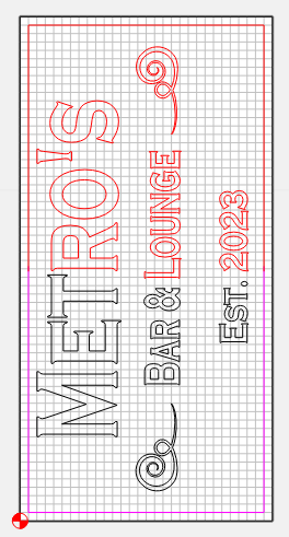
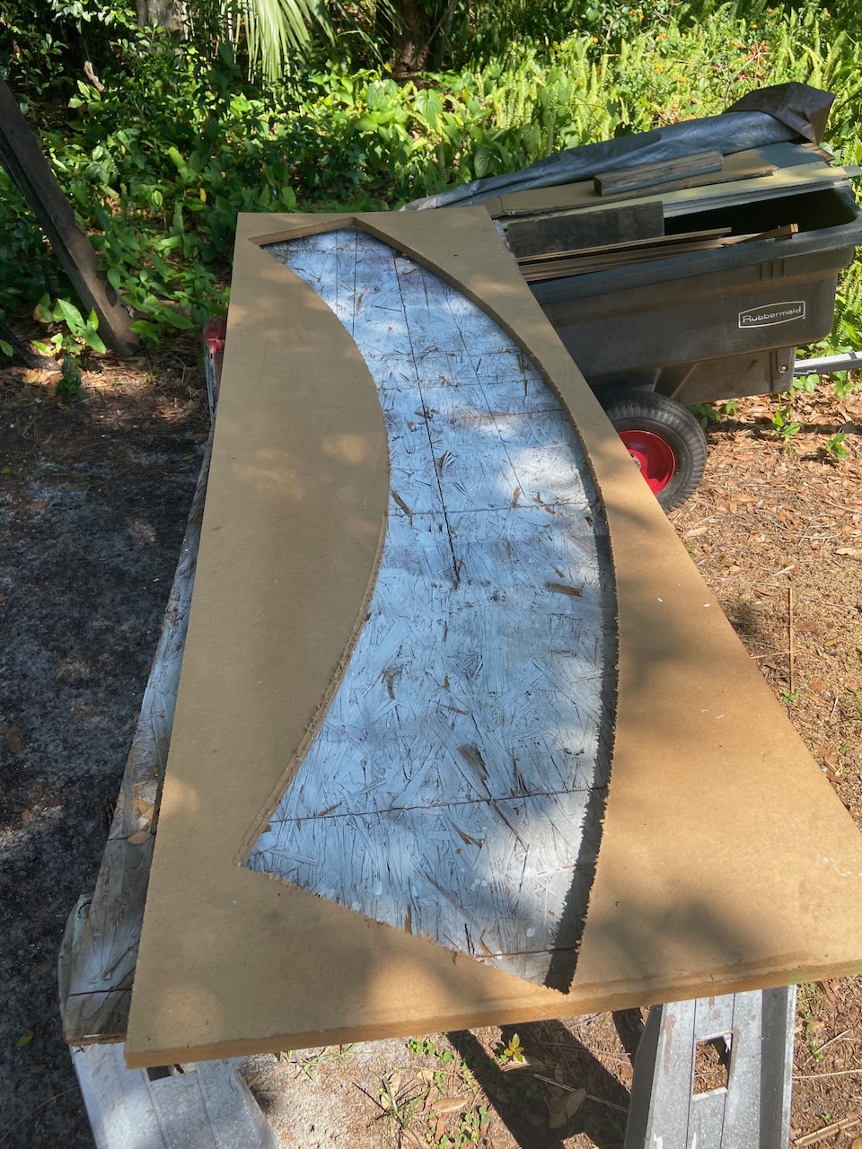
I’m gonna walk through the whole thing, my finish size for my sign is a 60" x 30"

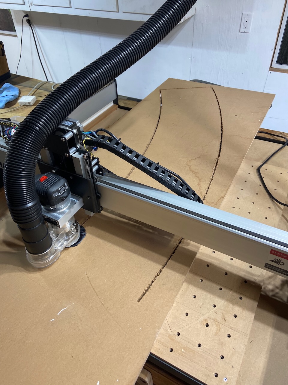
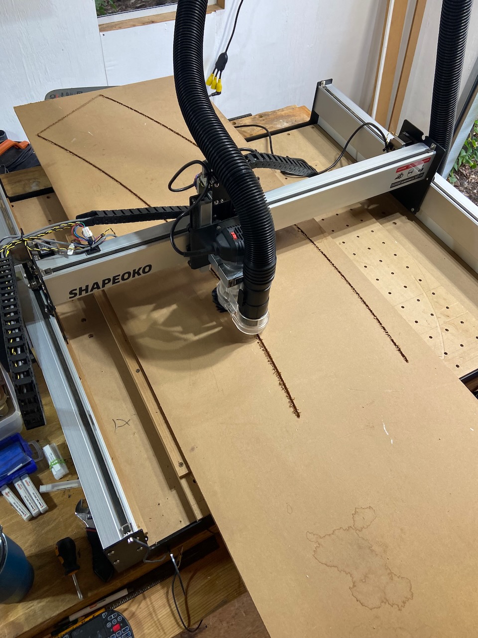
So I have my material pre-cut to 60x30, the X axis is a nonfactor since once i had it straight, i lined it with boards screwed into the bed

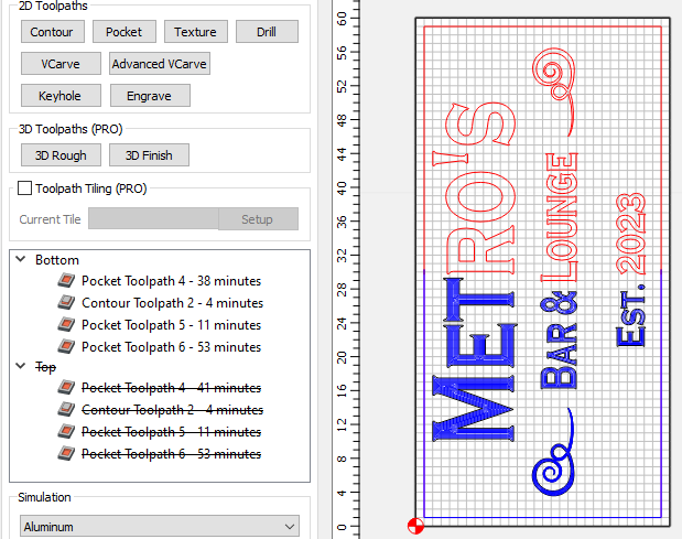
I have my file marked as 30" for height and 1" overlap

So i did my top cut first, at 30" down from the top of the material, and it worked well.

I began the 2nd part of the cut, the bottom, I had Motion home to previous X Y, and laid out my material to match that, right on the corner of my stock

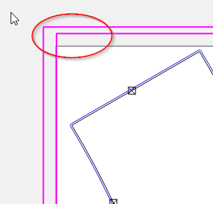
First thing it did was bump the Y in the back, i assumed at the time because it was trying to travel back 31" (30" height, + 1" overlap)

It bumped and i restarted everything to have the X and Y remain accurate

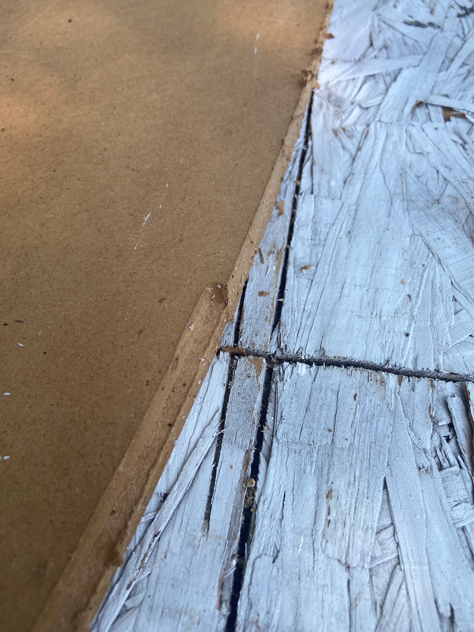
Assuming that it was travelling the inch, i started my Y 1" past my stock, in negative space. And it made a double line when it was supposed to recut the side of an R

What was i meant to do here? Because i’m just confused, if it was cutting the 2nd tile accurately, then why did it bump the back? If it needed the inch of travel, then why did it start a cut away from the area it was meant to start?

The Metro’s sign.c2d (488 KB)

I haven’t had a chance to try the new tiling feature yet but as I recall, move your work piece the distance you have specified in the Tile Height field. Do not add or subtract for tile overlap. You may want to experiment with a short tiling project on something like a 12 inch board with a design or text put in three tiles.

1 Like

You have your Tile Height in the Tile Setup set to 32". You’re moving your piece 30", so that’s what it should be set to. Ignore the overlap when setting things up. All the overlap does is cut a little extra on each tile to help try to blend the objects where the toolpath gets split into multiple paths.
There should be a 1/2" (1/4" overlap on each tile) strip through the objects on the split line that get cut twice, once with each tile.

Perhaps just a bad choice of words, but you should be measuring everything from the same point.
You’re setting your bottom tile up to the lower left corner (Your Zero for the bottom tile). So you should be measuring your 2nd Zero 30" up from the bottom left corner. If your stock is EXACTLY 60" this is theoretically the same. But it’s a good habit when you’rd doing multiple setups to measure everything from the same zero point (J-Corner).

It might help to understand what the Tiling feature is doing if you do a tile job without using it first.

Take a look at this file.
The Metro’s sign Tod.c2d (732 KB)

On the design tab I’ve separated the objects into 2 layers. You have to convert the text to curves to select individual letters. And cut the outer boundary into 2 pieces. I added a 1/4" overlap for the boundary.

image

Then on the toolpath tab, I separated the toolpaths into 2 groups, Top & Bottom.

image

Each group cuts whole objects, so there are no split lines other than the boundary, and since that is vertical edges, as long as you’re using your fence they should line up perfect.

So the only mystery left is how will you set your Y zero when you move the part.
You have 2 options. Leave the zero at the lower left corner of the job, and when you setup your Top half tell the machine you are starting at Y30. (Type in “30 [Enter]” instead of clicking “Zero Y”)
OR… Save Toolpaths for the Bottom as normal with the zero at the bottom left. Then change your setup to put Zero at Middle-Left and Save the Top toolpaths. Then you don’t have to move your Zero on the machine. Just move the part exactly 30".

So now if you’re a tiny bit off when you move the part. Instead of the misalignment showing up in the middle of a letter (R, L, 2), it shows up in between the letters, which you likely won’t notice.

5 Likes

Tod (with one d) is suggesting going back to manual tiling. I looked at your file, and then his, and his way is solid.

However, for whatever reason, I too would prefer to use the tiling “feature” in the software, rather than do it manually. At least for now to see if it works. I’m not opposed to going back to manual if it is more predictable. Also, there aren’t many overlaps in this project, as you can separate the cuts between letters. That’s rarely the case for my projects.

Mind you, I’ve tried a couple of tiling jobs, so I’m not an expert. I’m in the middle of three tile project (24" x 77") and having some issues as well. I will concur with Tod that you don’t need to factor in the overlap. I only used .5 in and it was fine. Also, from videos I’ve seen, you should measure from the top LEFT of your workpiece down to the exact tile dimension. In your case, 30" from the top left, although your 30"x60" makes it a moot point.

For me, I divided my job into three parts and settled on 26" to reduce the amount of waste. So I marked from the top left down to 26" and 52" and used those for reference points. This resulted in two good cuts, but the final (bottom) run was off by 5.5mm on the horizontal (Y) axis. That doesn’t make any sense to me, but I’ll need to see if it was just a glitch. I’m making a semi-rounded book case for my daughter, so I need three identical pieces. Attached is the file and pics of the process.

Has anyone else had any issues with the Y-axis shifting, presumably in the software, as my fence definitely did NOT move. ??
230509 Becca Bookcase.c2d (52 KB)


After I adjusted my Y-axis (which is how I knew it was 5.5mm) I managed to align the contours to an acceptable level.

The software is measuring from the BOTTOM LEFT.
Your stock is 77" (on the VERTICAL (Y) axis), and you set your tiles to 26"
3 x 26 = 78. If you measured your 2 top tiles from the top left corner, and your bottom tile from the bottom left corner, this would explain why they are not lining up.
You can see there is a 1" gap at the top of the 3rd tile

image

Your job is a perfect candidate for the tiling feature. A single long part aligned closely with the Y axis.
When you have a bunch of features, particularly with closer to horizontal (X) edges that cross the tile boundary or the overlap, it’s better to cut that whole feature in one tile if you can.

Tiling does 2 things: Any path that crosses from one tile to another (Including the overlap) gets split into 2 overlapping paths.
And the ZERO for each tile is translated by the “Tile Height”
Whatever you set your “Tile Height” to, that’s how far you should be moving the stock each time.

1 Like

Thanks for the explanation. What you’re saying makes sense. I could have sworn on the CC tiling video, Kevin said to measure it from the top of the workpiece. In any event, I’m still working on this bookcase so I’ll try it as you’ve recommended.

Thanks, again!

Kevin did, indeed mention measuring from the top. Right after saying that the Zero would stay in the same place (Lower Left Corner). He also said being an 1/8" off is OK. ???
You could do it this way. (I wouldn’t, & won’t). The critical thing is that you move the stock the same distance as the Tile Height in CC. If you measure the top tile from the top, you should also measure the bottom tile FROM THE TOP!!!
In his video, he obviously uses a guide mark for moving the stock at a different point than his zero.
This is OK, and truly arbitrary, as long as he’s moving it exactly (or close) to the Tile Height.
He started with the top tile, so when he’s moving his sheet he is standing behind the machine, so maybe it makes sense that he put his mark on that end.

2 Likes

My error was in the CC file with the 77" vs 78" workpiece. That’s good to know, as I can attribute it to my own error and not the software.

As you said, the golden rule is “The critical thing is that you move the stock the same distance as the Tile Height in CC”.

thanks!

1 Like

This topic was automatically closed after 30 days. New replies are no longer allowed.