hello all, I am a brand new CNCer so bear with my likely basic questions please. I am cutting some marquee letters and a few of them oar bigger than my 2’ capacity on my 5 pro i just got. I watched the video on tiling but sometimes I feel Kevin goes through things so fast that I struggle to understand them. he suggests making guide rails for the x axis which I want to do. he states he used his 1/4" mil do face the guide blocks, how do I do this? do i set something up in CC for a tool path, and if I do what would that look like. Or do I do it manually with jog controls, if I do that how do I turn on my spindle? (i have the VFD spindle). once that is done do you guys have suggestions for easy tiling alignment? TIA
I think you mean the Y axis (the left side)?
I also think they turned off the ability to manual mill with jog. You would have to make a program. Or type in the commands in the command line. M3S10000 turns on the spindle at 10000 RPM.
G0 X0.125 Y0.0 rapid moves to your start point
G1 Z0.0 F20 Moves Z down to zero. (set your Z zero at the table)
G1 Y24.0 F60 Moves the tool along Y to the upper extent of motion (I’m assuming 24")
G0 Z3.0 rapid move Z up away from the table
M5 turn off the spindle.
But it would be as simple as creating a vertical line and using a contour path to mill the right edge of the line. Then just setting your X zero so it takes a thin pass along your fence. i.e. set your X zero just a hair to the left of the edge of your fence.
The simple & most basic key to tiling, using the tiling feature in CC, is the tile height must be the exact distance you move the part to machine the 2nd tile. Whether you mark the edge of your part and mark the fence, or use dowels or some other method of indexing the part. A lot of this will depend on what you’re cutting, whether you can keep a straight flat edge on the left side to move along your fence.
1 Like
Thanks, that’s very helpful
Good morning, or afternoon depending on where you are. I tried what you recommended and it did not work out, I’ll tell you what I did and maybe you can figure out where I went wrong. I drew a straight line on the very edge with my origin in cc. I assigned a 1/4” end mill contour path on the inside. When I ran the machine it was cutting at different paths when coming forward and backward, they were about a 16th difference, any ideas? I think I am overthinking this, but in cc my “material” is to the left of my origin whereas in the real world my fence is to the right of the origin, so when I zeroed I was maybe 1/64th from the right edge of the fence, is that the correct place to zero? Thanks for your help, this is all very new to me and hurts the brain sometimes!
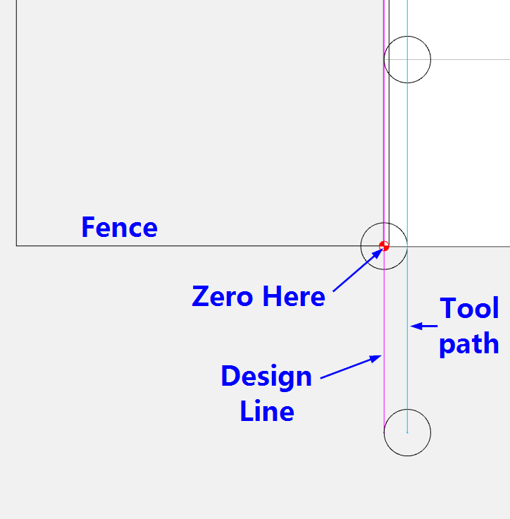
OK, so when you program it, you want a line going up the left edge right on the zero point.
set your depth to the height of your fence, and the depth per pass on the tool to something larger than that depth. (I just set it to 1.0). You’re going to take a really thin cut only on one edge of the fence, so a full depth cut should be OK. It should make one cut. That’s it. No going up & back. You may need to switch inside/left to outside/right. It’s an open vector, so it doesn’t know which side is left or right, and there is no inside/outside. I usually make my line a little bit longer so it starts off the material.
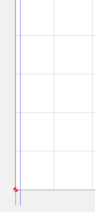
Then when you attach your fence, set the zero about 1/64" from the right edge of the fence. Line up the center of the tool, not the edge of the tool. So the tool will actually move to X0.125, and then straight up Y.
2 Likes
that worked, I really appreciate it!
1 Like
This topic was automatically closed 30 days after the last reply. New replies are no longer allowed.