Tiling this .c2d on shapeoko xxl help please!

Back again. 47.7" long with no clue where to begin on this thing. Not even sure if I’m on the right path to success here. MYTRYSAK.c2d (108.6 KB)

Of course you are, but sometimes the road to success is long and windy :slight_smile:

I assume you have already seen this great post from @WillAdams about the approach.

Disclaimer: I have the smaller SO3, with no access to three of its four sides, so I could never try tiling myself. Take everything I say with a grain of salt and suspicion. I’m replying because I may well learn a thing or two myself, as we collectively walk you through creating the correct CC design to do what you want.

I understand you want to cut this on a XXL, the first thing to decide is whether you will tile by sliding the large 48" long stock from the side of the machine, or from the back/front. Because then you need to align things in CC accordingly.

You current design looks like this:

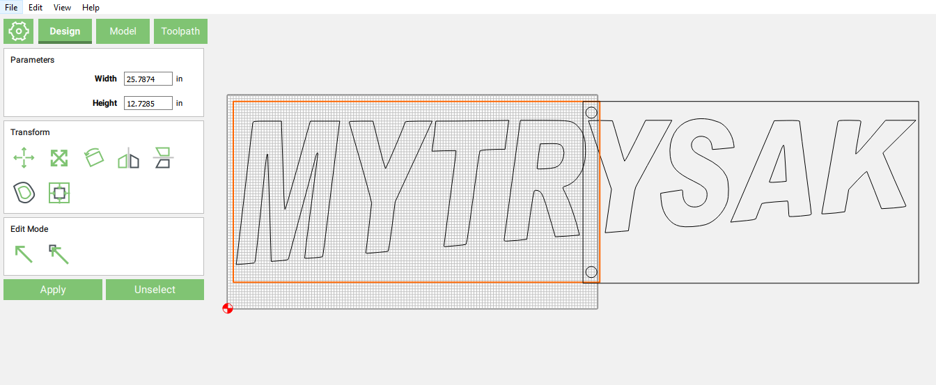
  • It’s setup to tile in the left/right direction, is that your intent ?
  • The M looks very close to the left edge of the stock, is this intentional ?
  • the circles are 0.3937" in radius, does that match the size of the dowels/registrations pins you will be using to align the stock ?
  • you will need (at least) two more circles, on the left of the first panel
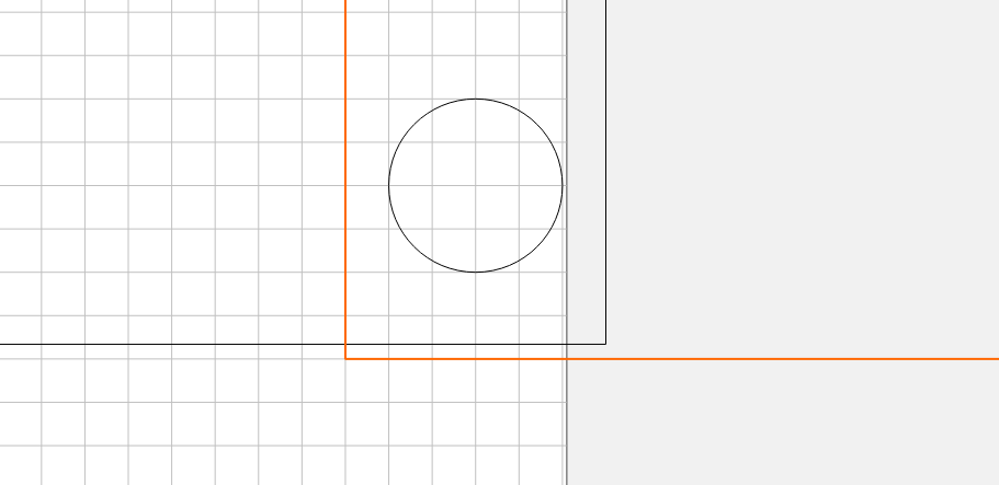
  • those circles seem to be too close to the top of the second Y (they may get cut when you do the letter cutout)
  • the dimensions of the two panels do not quite match, the right one has a different height, so they do not align at the junction:

3 Likes

Joe, along with Julien’s comments, your lettering seems to be sized and placed so that you are utilizing as much of the board that you possibly can. Perhaps you are limited in the size of board you have available?

This is probably not quite the right approach. You’ll want to leave enough room around what you are carving so you have room for the registration dowels and clamps.

Your lettering may have to be reduced and/or moved.

2 Likes

Yes, left to right is correct. The placement of the M is because I resized it to almost the exact size I need. Other than that there was no rhyme or reason. The circles are a confusing step to me. How do I calculate where they go correctly? Do I cut them before I start the letters? I did see that the 2 panels were different but I wanted to get something up to show everybody to see if I’m even close to success because I’m on a time crunch with this. I did see that post from @WillAdams, it’s very informative but it’s still beyond my skill limit.

Ok. Not limited on board size just thought I would try to conserve since lumber is almost as good as gold today. The registration dowels are confusing. I don’t understand that completely. Not sure why I can’t just clamp it down, zero the machine to the bottom left, run the first few, mark a line at the zero point and 2 straight lines on my table, then just slide it down and revert and finish the cut. I know there are problems there but I’m stuck on figuring out what they are. Maybe I’m making this more difficult than it needs to be by overthinking?

@RunawayTrain,

You can think of it this way: you need
a) at design time, a way to accurately “slice” your design in Carbide Create into individual tiles, an create separate toolpaths for each one
b) at run time, a way to slide the long stock by a precise amount, matching the width of the slices you defined in CC, and ensuring proper alignement during that shift.

Starting with b):

  • you could indeed try and draw a line across the stock corresponding to where the first tile ends and where the second tile begins, and slide the stock until that line aligns with where the previous zero was. But there are two problems : 1) how/where would you draw that line ? If you measure a distance with a tape, depending on how well your machine is calibrated, the actual cut may not end right there. 2) how do you precisely slide and reposition the stock based on that line ? Eyeballing is error-prone, and the sum of errors of 1) and 2) will probably be lead to a visible shift/offset between tile. Even a 1mm error would show on the piece
  • so it is “just” more precise and convenient to add relocation pins in your design:
    • you could put them anywhere, as long as in each tile they are in the same position versus where the parts to be cut are. The idea is that since you add them in the design, and tell the machine to drill those holes, no matter what inaccurracies the machine may have, at least it will give you a repeatable positioning.
  • they are convenient because when you will slide the stock, no need for any eyeballing or manual alignment, you just slide the stock so that the NEXT set of holes falls on the dowels, it takes a second, and you are guaranteed to have a precise position.

So considering this, for a) you just need to use some geometry in CC to align your tiles and their positioning holes, with respect to the part you want to cut (and vice versa). Drawing the overlaid tiles as in Will’s tutorial is one way, but if this is clearer for you check out the video in the wiki about this guy who does it differently (in another software, but the idea applies): he just draws lines across the design at precise offsets, then cuts off the extra parts above/below those lines :

The important thing is to find a way to be able to shift the “slices” of your design back against the origin defined for the toolpath (lower left corner, most likely)

Hopefully I did not confuse the matter further for you.

2 Likes

Your plan will work. As @Julien says, you’ll have to be precise. For your design, I’m guessing you don’t need sub mm precision.
Try it on a smaller scrap first.
Are you feeding the stock along the X axis, under the rails?

2 Likes

I’m a noob, hence all the questions. A buddy is getting married and his soon to be wife wants a 47.7” long name cut out but I have no idea where to begin. The wiki on tiling is using terms that are way beyond my skill limits and I’m not experienced enough to spend the kind of money I’d have to spend on the vcarve software. I tried the vcarve trial but it doesn’t allow tiling. Any help designing a gcode for this project on carbide create would be appreciated. Happy wife happy life, and I don’t want to be the best man who disappoints the bride. Help!?

Please design this at full size and post it here and we’ll do our best to walk through this with you.

You may find the glossary helps with terminology: https://wiki.shapeoko.com/index.php/Glossary

and I wrote a bit about the basics of using Carbide Create at:

https://willadams.gitbook.io/design-into-3d/2d-drawing

If you’ll let us know what you’re having trouble with, we’ll do our best to work through this with you.

2 Likes

Thanks for guiding me to that write up too! That is incredible and I will definitely be using that as a reference point from now on!

Sure! Just draw a pair of overlapping rectangles which are smaller than the working area of the machine which encompass full letters and draw in holes to register/index them as two cuts.

If you continue to have difficulties post the .c2d file

Ok. This is what I came up with. Is this correct? How do I get it to go between the letters but not cut them off individually? And what do I do with those circles I made? This is the backer for each individual letter that I need to cut…MYTRYSAK.c2d (108.6 KB)

I’m not exactly sure what you are looking for. Do you want a flat plate that outlines all of the letters?

This was made with a polyline using the nodes for the outside corners of the M and K as well as the top and bottom of the S (which is a bit larger than the slope between the other letters). What you see here is an offset path outside by 0.1". There a many different options depending on the look you want to achieve. I haven’t done any tiling my machine is against the wall in the back so pass thru isn’t an option in my current space.

No. What I need is a complete backer for the letters that I will cutout individually. But I need it to cutout the center of the “A” and “R” and to go around each letter but keep it complete.

Alright, perhaps this will help. I have toolpaths saved in the file as well. file-1 is the first part and contains the wasteboard operation to cut the holes into and the first tile operation. So you’d run the first tool path on that file on your wasteboard zeroed to the front left corner of the shapeoko. The only zero you’d need to change is after this toolpath, setting a new z height.for the cutout material.
Not sure how large the stock is (or what material is) that you are cutting the backer sign out of but you can plug those values in. Put the stock on the wasteboard hopefully positioned close to where you put the pocket holes into your wasteboard. I find it easier to buy bigger stock than I need and cut out the object from that bigger stock. filename-1 toolpath group 2 should have everything you need to pocket the letters, and also cut out the backer sign.
filename-2 should have holes near where the y will be. Use a 1/4 in dowel to position those holes near the back of the machine into the holes you made in the wasteboard, then run the operations in the part 2 group. That should be it for the backer board. The letters can be cut out individually from the machine. Though I recommend making them just slightly smaller, because getting exact size letters to fit in exact size holes is…challenging.
Hopefully this is clear enough to get you going. One thing you will have to watch for is the stock wasteboard sits lower than the steel frame on the shapeoko. I recommend making a riser out of MDF to get your part to sit above the steel frame. Also highly recommend blue tape and super glue method of work holding.

Then you’d hopefully have something that’s 1/4 inch around, like a dowel that you can put

If you haven’t yet I highly recommend checking out Carbide3d and Winston Moy’s youtube videos. Winston has an older getting started playlist here:

And a newer one on the carbide 3d channel:

Workholding video that can also be helpful:

It also might be helpful to just run the letters first to get to know the machine.

MYTRYSAK-2.c2d (123.8 KB) MYTRYSAK-1.c2d (131.0 KB)

2 Likes

To keep it complete there needs to be material connecting the letters. What does this look like? Do you want to have a rectangle across the bottom they all sit on or a more cartoony bubbles around the letters that blend together? Perhaps a sketch would help us visualize what you desire.

Are there two threads for this same project?!

This is what I need to do. This is the backer to which I will glue slightly smaller cutout letters to.MYTRYSAK-00.c2d (1.3 MB)

This is what I need. This is the backer board to which I will glue cut out letters to. MYTRYSAK-00.c2d (1.3 MB)