Usual preface, I’m with PreciseBits so while I try to only post general information take everything I say with the understanding that I have a bias.
The “infinitely sharp” tool thing is a pet peeve of mine both in software and tooling. It’s literally impossible to make a tool with a “infinitely sharp” tip as even if the material and grinding wheels could somehow allow for it infinitely sharp is infinitely weak and that tip would last until a slight breeze hit it.
That aside…This gets into a whole bunch of complicated stuff related to how tools are defined and ground. As Liam said your best option is to define a tool with the features of the tool. So these would most likely be best defined as tapered ball-nose cutters with their half not included angles.
However, if you are defining them as a flat tipped engraving or tapered tool the simple version is subtract the width increase of the taper for the radius of the cutter. So in these cases:
#501
Depth to width ratio: 1:11547
So 0.005" * 1.11547 gives us ~0.00577". Which we would subtract from the 0.010" giving us a projected flat diameter at the tip of the ball of 0.00423".
#502
Depth to width ratio: 1:0.7279
So 0.0025 * 0.7279 gives us ~ 0.00182". Subtracting the 0.005" now gives us 0.00318" for the projected flat tip.
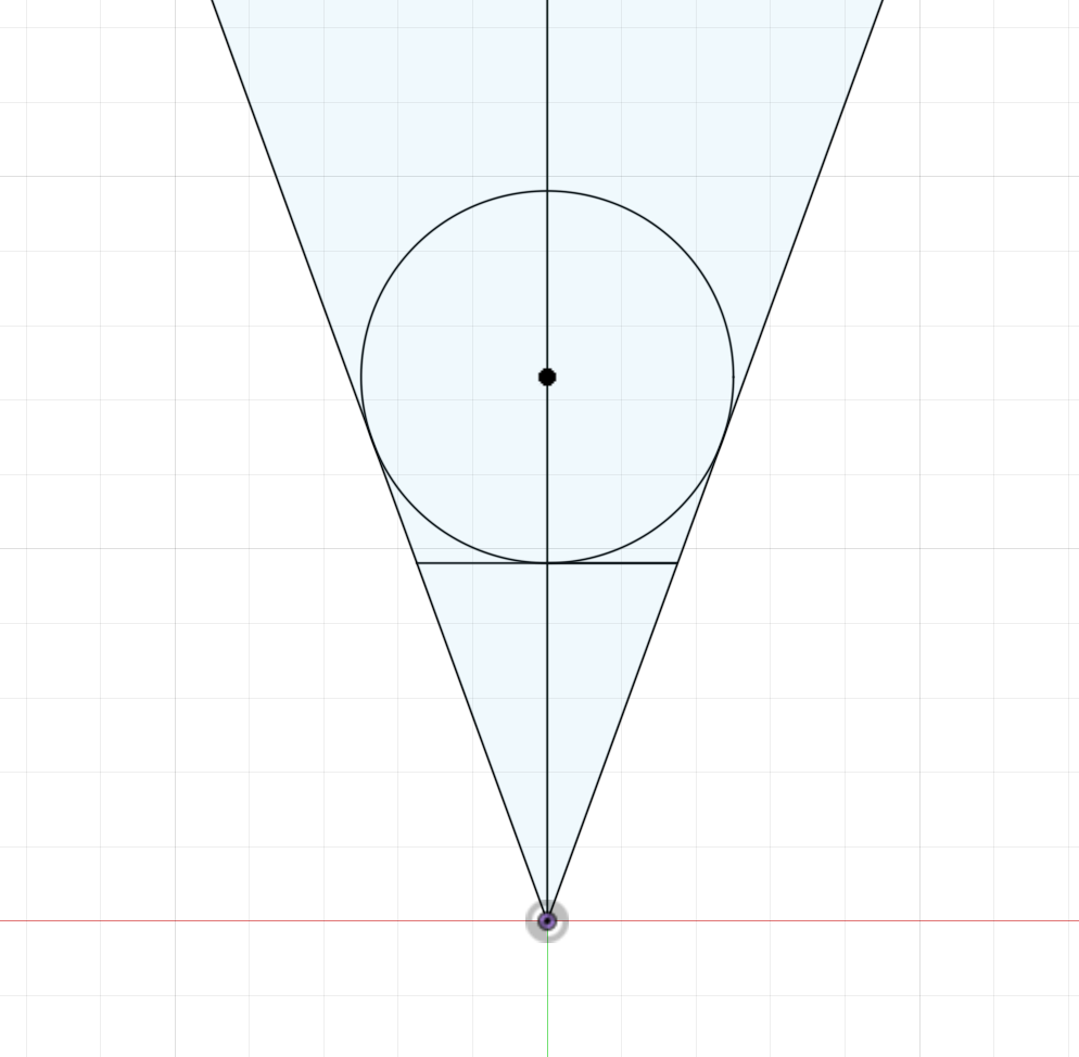
Those should work correctly for most software to most accuracy needs (depending on geometry, see below). However, as your drawing shows the actual meeting point of the ball is not at the radius. These can be calculated for but everyone does different things so you need to know the exact length of cut and exact diameter at that length of cut.
Edit. Forgot to subtract the lost distance from tipping the cone (I blame a lack of coffee)
As an example if I grind a presumed perfect cone at a 60° included angle, grind flutes with a 0.1078" cutting length to the edge of a 1/8" blank (60° from 0.1245" to “infinitely sharp”) , then add a 0.010" ball creating a new cutting length of ~0.1028". It will change the taper of the tool to ~60.7° instead of 60°, the diameter at the tangent will be 0.00863", and the diameter at the 0.005" from the tip will be 0.01159".
If we use the above we get a ratio of 1:1734 which works out to a projected flat tip diameter of 0.00413" if using the 0.0100 diameter or 0.00572" if using the true 0.01159".
End edit… Definitely not enough coffee today.
Alternatively, we could instead grind a tool that is 60° included angle finished which would be a cutting length of ~0.10416". This would result in a diameter at tangent of 0.00866 and 0.01155" 0.005" from the tip.
There’s a few other ways to do it too but these 2 are common. There’s also the issue of how CAM handles things.
I hope at least the first half of this is useful… Doubt the second half is. Let me know if there’s something I can help with.