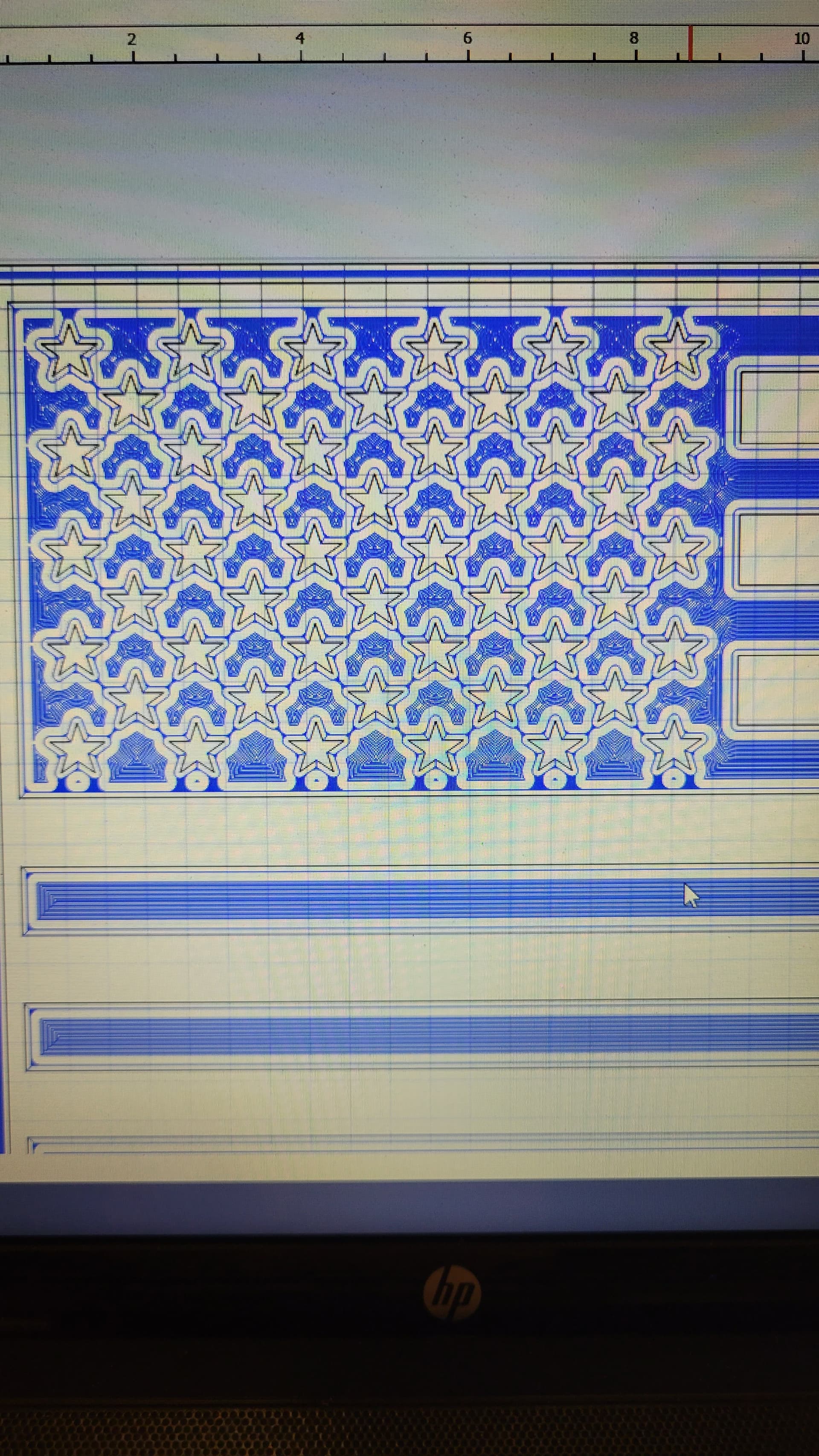
How accurate is the simulation vs the actual tool paths? I’ve been messing around with flags recently and had this come up. The blue toolpath shows some ares in the union that won’t be cut. However, the simulation shows they will.
I’ve seen this in past projects with lettering inlays as well. I took a gamble and did that carve, based on the simulation. Turns out, I should have “listened” to the actual toolpath because parts were not cut.
I haven’t run this one yet, because I don’t want to waste 4 hours and the lumber if it doesn’t carve like the simulation shows. Let me see if i can find the lettering one that didn’t work and post those pics.
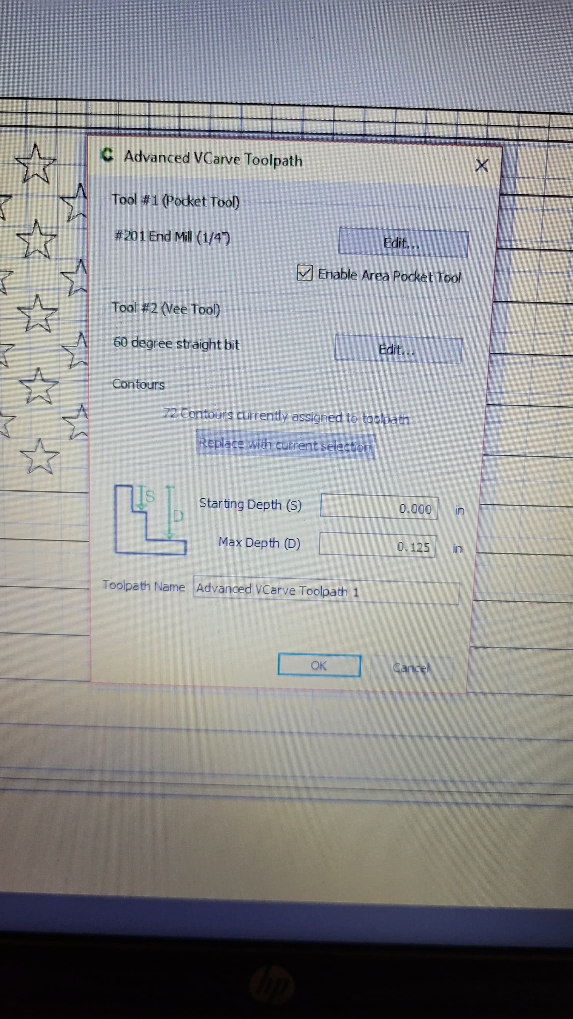
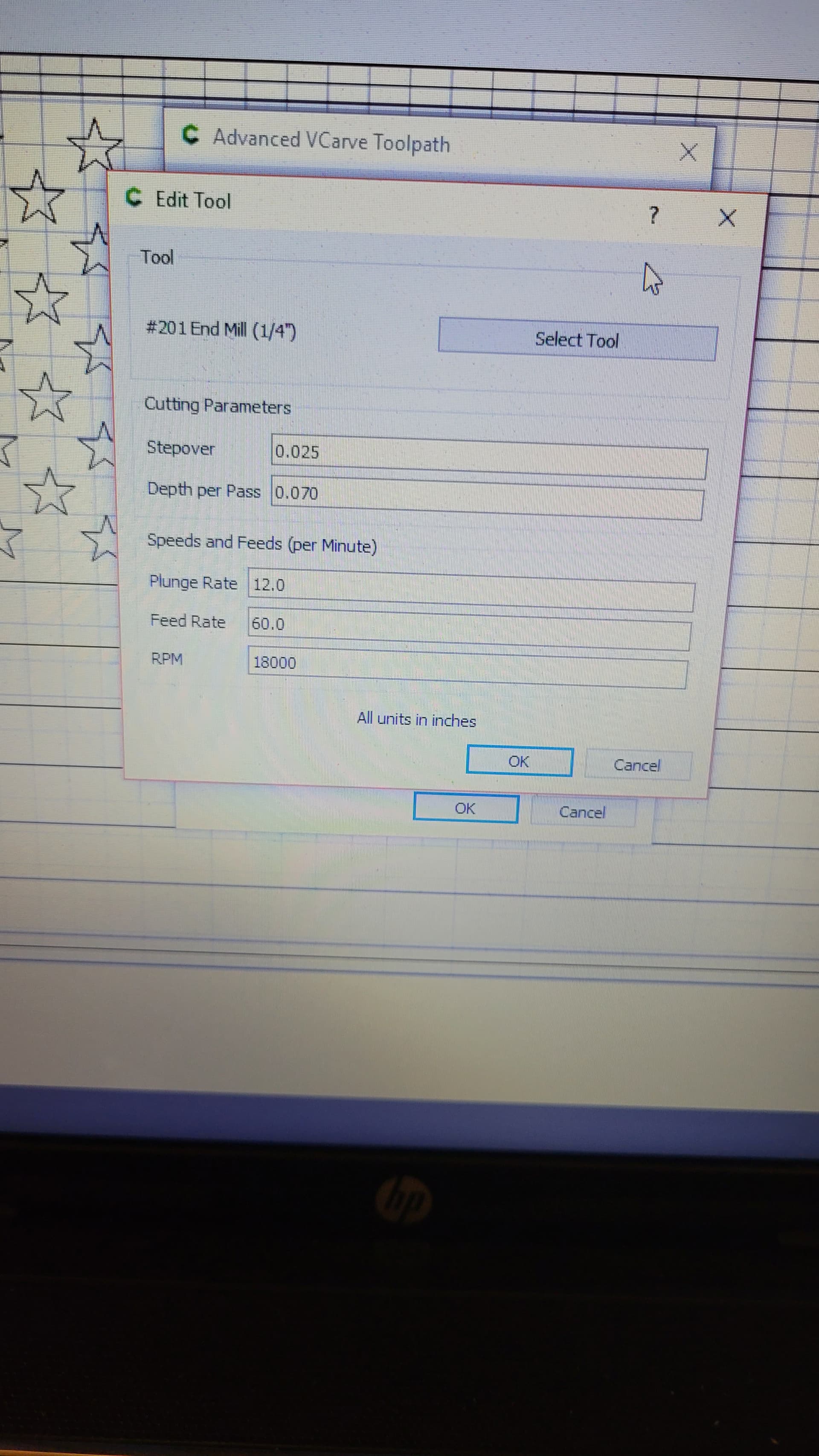
In an attempt to figure it out, I set the pocket tool to a .125" end mill and it for sure shows the toolpath getting everything. However, the simulation is exactly the same with the .125" and the .25".
I suppose maybe I am just mis-interpreting the blue toolpath?? To me, it seems based on the photo I posted that there are some areas around the stars and below the bottom row of stars that aren’t going to get carved. I get some of the same areas in another portion of the flag as well.
A ¼" endmill is larger than a ⅛" endmill. The toolpath shows the path that the center of the endmill follows. The ¼" tool is cutting further from that center path.
I understand the difference in diameter and the center of the toolpath. I’ve carved this same flag, but 32x17 with the same .25" endmill as the pocket and the toolpatch showed blue all the way to the edge of every vector line. Larger dimensions means larger spacing between vectors obviously, but why would they show different toolpaths but the same 3d simulation?
I’d find that 32x17 file, open it again, and have a closer look at the toolpath. The blue line should be 0.125" from the vector. It will appear closer for a bigger project because you’ll be shrinking the image to fit the screen, but should be exactly the same physical measurement.
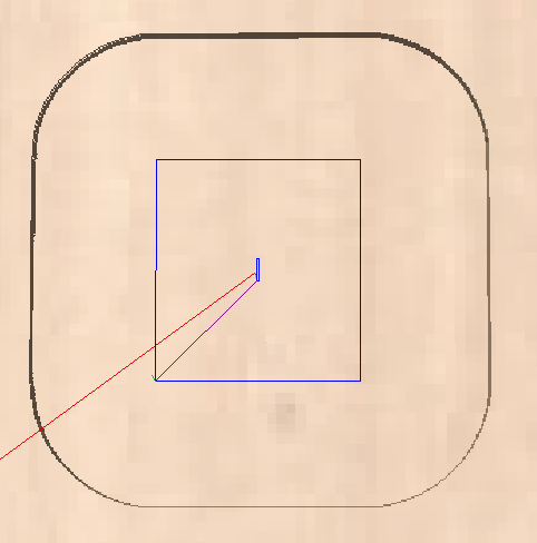
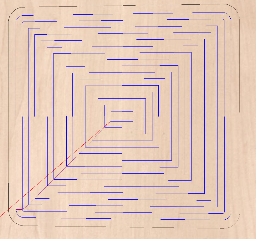
Here’s an exaggerated example. Both use exactly the same endmill but one toolpath appears to be much farther from the edge of the shape due to the difference in the size of the pockets.
And the same example applies to the same size square cut with 2 different tools. The smaller tool will have more passes. Yet they both remove the same material. The corners are different, but you are v-carving so the corners are getting cleaned out.