On my 3 week or so with CNC, so this is likely something very easy and hopefully I explain correctly what I’m trying to do.
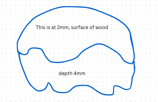
What is the proper way to pocket the following (very crude) image such that the top is 2mm down from the surface and the bottom portion is 4mm down from the top/surface?
Basically, in the middle we have a very irregular line but this was done from an import/trace (let’s say). Given that the toolpath is associated with a vector you would have to ensure there is a vector for the top and one for the bottom sections of the image. However, due to the irregularity of the line in the middle, it’s difficult to get them the same and align perfectly.
Perfect world, they could share one line and you could say pocket 2mm above and 4mm below, but clearly that’s not possible.
No doubt this is just lack of knowledge/current capabilities, so wondering how this should be done (correctly).
Not sure if I’m making sense here, so applogies for any confusion.
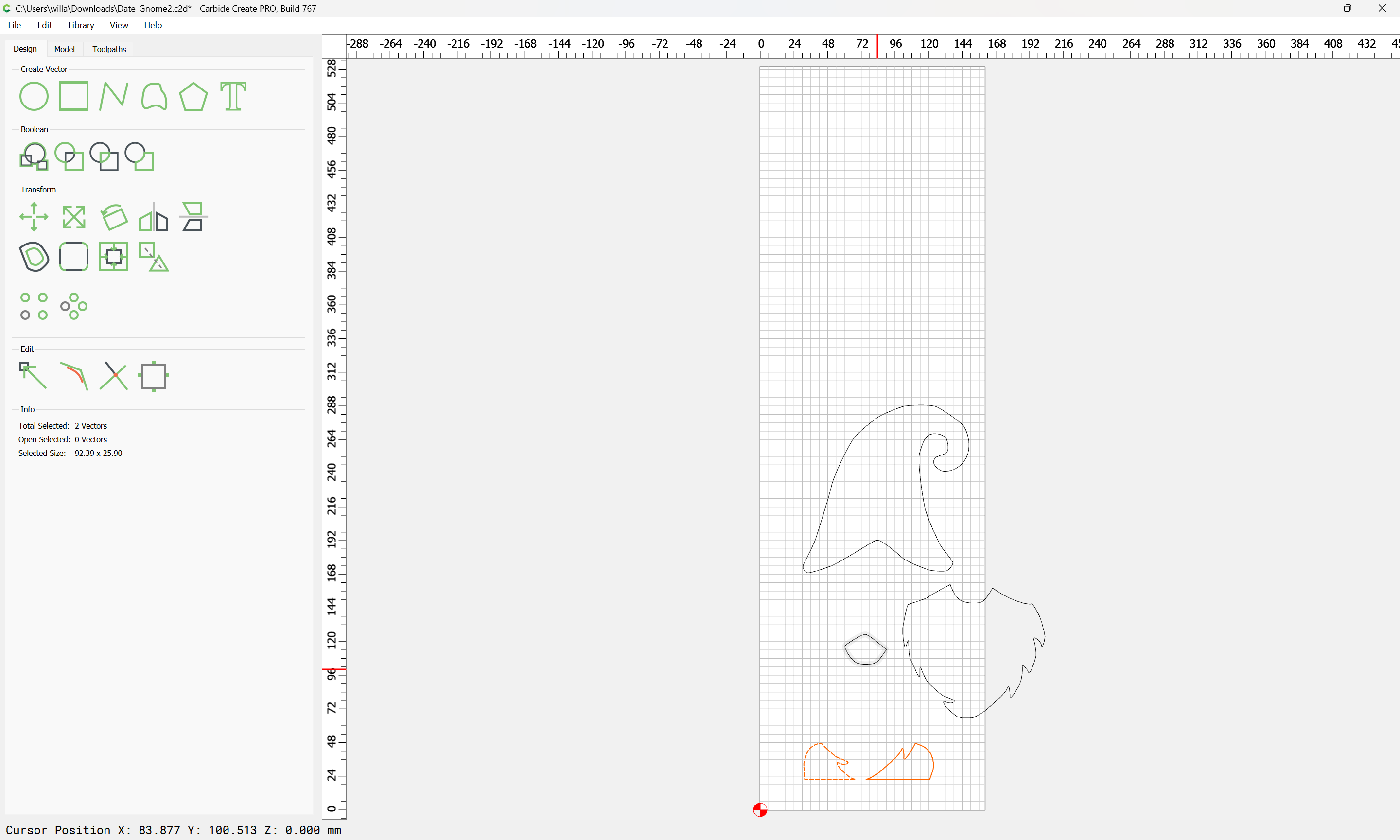
Here is a down-and-dirty attempt. Took your image from the post. Converted it to .JPG, Trace in CC, Ungroup, Moved bottom image up to almost mate, Added Tool Paths for each section, and then cut out the outside line with a pocket. I use Blue Tape and CA glue so I don’t use tabs.
Like I said this is down and dirty. If you want the lines to mate better, use Node Editor
Thank you! Here is a c2d I’ve been playing around with. The goal is to have the hat be 1mm down, the beard at 2mm down and feet at 2.5mm down, for example.
Ok, Here is your file. Used 3.175mm .125 bit to cut it with to better fit into the corners. You have probably already done this while I was playing with it.
You will note I changed the stepover smaller to have a slightly better bottom finish Date_Gnome2.c2d (348 KB)
Have fun with this. Have more questions, we will walk you through it. This is my free one for you Heck it is all free.
I will note that one can (potentially) achieve a more efficient toolpath setup if rather than having 4 discrete regions (one for each separate depth, w/ the two feet here being described as one region):
one has 4 regions which overlap, one for each (cumulative) cut depth — assuming of course that you don’t need to cut each region sequentially for an epoxy pour or painting.