Hi is there any way to edit a toolpath sensitivity when creating toolpaths?
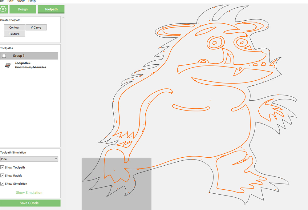
For example if I create a cartoon dog and the toolpath goeas around the outside of it but the same toolpath may also pickup the eyes, so if I want to not include the eyes from the tool path how do I do that please?
thanks.
You have to ungroup the different parts of your drawing and select only the ones you want to include in your toolpath.
3 Likes
Many thanks Luc.
I tried that but then it shows a striked out line on the left for the toolpath.
I had a fiddle around using shift and found I could select different things in the image to create different toolpaths but to be fair Im not sure if this is correct or not and if Im just winging it and being lucky.
The attached image is just large to begin with because I dont know how to zoom in as IM on a laptop and dont have a scrowl wheel so I resize once ive edited the toolpaths to fit the bed.
Many thanks.
1 Like
Yes using the shift to select several vectors is the way to go, you can group those that you want to keep together so you don’t have to manually select them every time you want to modify something. Looking at this drawing, you may want to clean up your vectors and the dots everywhere. You should get yourself a USB two button mouse with a wheel to work, they cost less than $20 and it is required for accessing functions most CAD software.
1 Like
Thanks Luc, yeah I’m going to get a mouse you’re right I need one, I’m just getting to know things now so starting to add extra accessories I need.
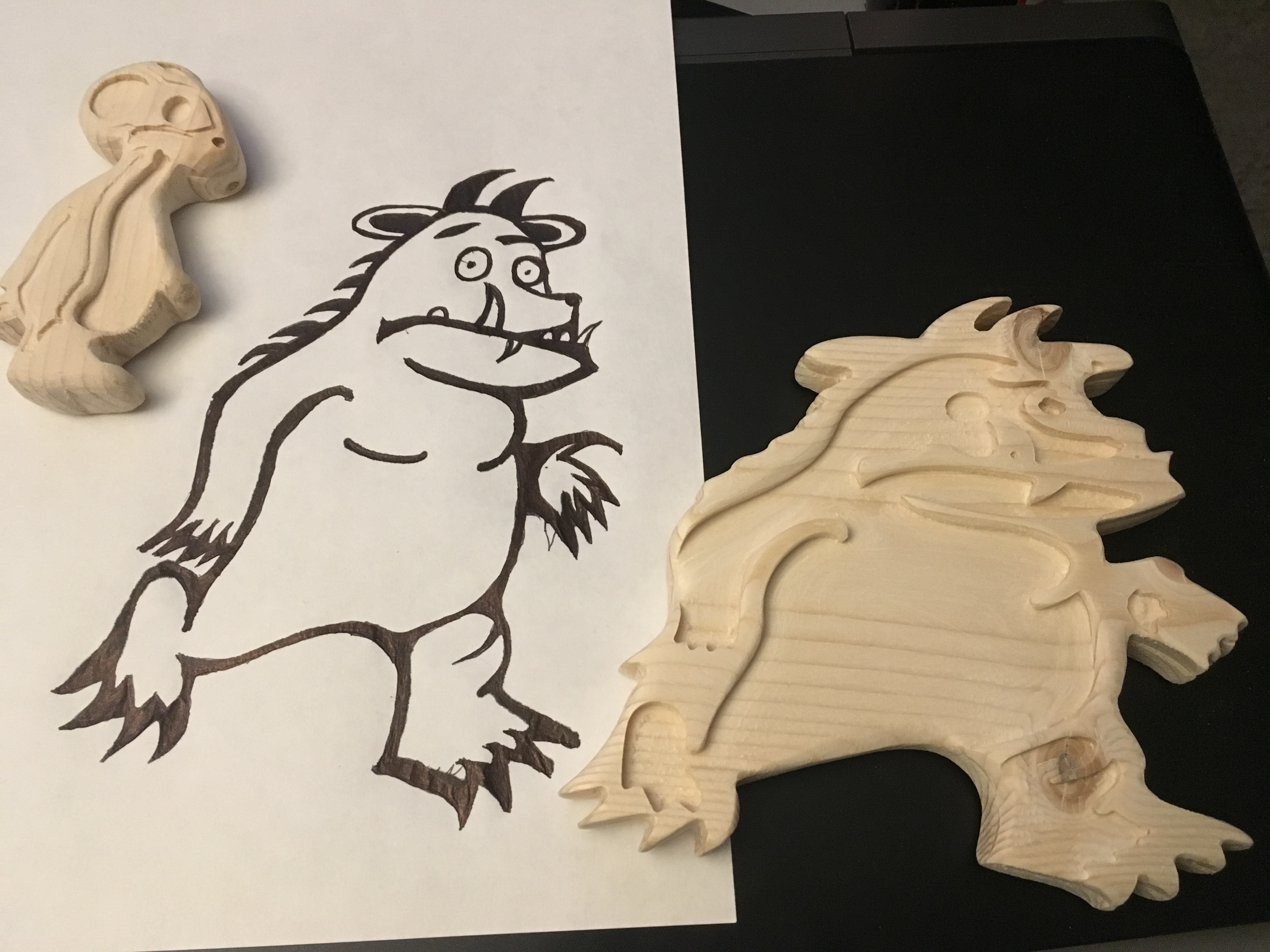
The vector thing is baffling me as it seems to really show up once I edit toolpaths, is there a secret to cleaning them up?
The cut didn’t come out too bad but I need to make some adjustments and do it again.
I have Inkscape but my word it’s a horrible workflow.
2 Likes
Can you share your image or the svg?
2 Likes
How would I go about being able to make this a two sided image rather than just one sided?
thanks.
hi yes here he is.

Carbide Create does not have a function for that (other software like Vcarve have the function built-in) but by carefully planning the project you could do this. Here is the jist of it. YTwould need to set the project origin in the middle then center the image and place holes in strategic locations to ensure alignment. When you mill the first side, you also mill the indexing holes all the way to the wasteboard. You need to perform the cutout on the second side. You would then flip the outline of the image in CC ensuring it is still placed in the middle. Place pegs in the holes all the way to the wasteboard to ensure everything is indexed. I have a board with threaded holes on a 2X2in grid so I use those holes for indexing the work.
1 Like
Flip it horizontally in a drawing program?
1 Like
Thanks for the reply.
I’m kind of confused because the advertising for the Nomad shows a little 3d character being cut using a flip jig, but I’m assuming there’s a limitation to the size of that.
I don’t know the flip jig but there are different ways to do the same thing. The thing is that you have to flip the workpiece precisely over a pivot point that is the same in both software and on the machine. How you do this is up to you, since I have a grid system to hold my work pieces, I can align precisely when I flip to do the second side. In some cases, you can make a fixture to hold the work in a precise location when you mill your project.
Here is another way. Lets say that you use a square work piece and hold it with an L fixture attached to your wasteboard at the bottom left (SW) corner and you ensure that your design is centered on the work piece. When you flip the work piece and rest it against the fixture, the workpiece would be aligned in both X and Y and the center would remain at the same place so you can mill the other side. So your X and Y zero remain at the same place. Provided that you have enough material left over the Z would also be almost identical. This is why you have to wait until the second side to cut the contour because you need the work piece material edges intact to align it properly.
Another point, the fact that a flip jig is used does not also mean they used Carbide Create, many projects shown by Carbide 3D uses different software, Winston likes Fusion 360 for example. As I said, you can do this with Carbide Create but the function is not built in like it is in other software, it needs you to be more careful and precise when you design your project. In CC you will need to create two separate projects for front and back. Instead of seeing an outline of the front side when you design and align the back, like you would in VCarve for example, you would need to rely on measurements to a single pivot point using the horizontal or vertical flip function trusting that everything aligns properly on the back with the front.
I think there are a few threads and maybe some training material/videos on how to design and mill a 2 sided project you should search here and on YT.
I hope this helps.
2 Likes
Yes, the flip jig is limited to 3x5 stock — it has support in MeshCAM, but one could use it from Carbide Create as well.
1 Like
do you have a picture of your systemas an example please Luc?
OK, here are a couple of jigs to hold your project in place while you flip the workpiece.
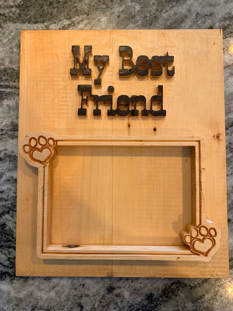
For example, I used the corner brackets to create the slot to insert a photo behind the frame for that project.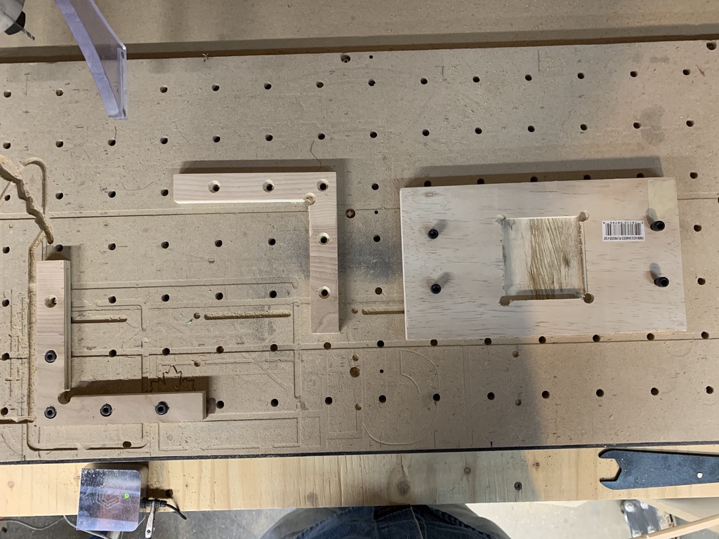
Some others I have used were part of the workpiece and got destroyed when you do the final contour cut.
The other jig lets you insert a piece in a slot to mill it then you can flip it and the workpiece stays exactly in the same position to mill the other side.
The key is to have a method to keep the workpiece indexed. I rely on my wasteboard that is based on a 2in X 2in grid.
I hope this helps you understand.
2 Likes
That’s brilliant thank you.
The larger bed helps too for bigger projects I guess.