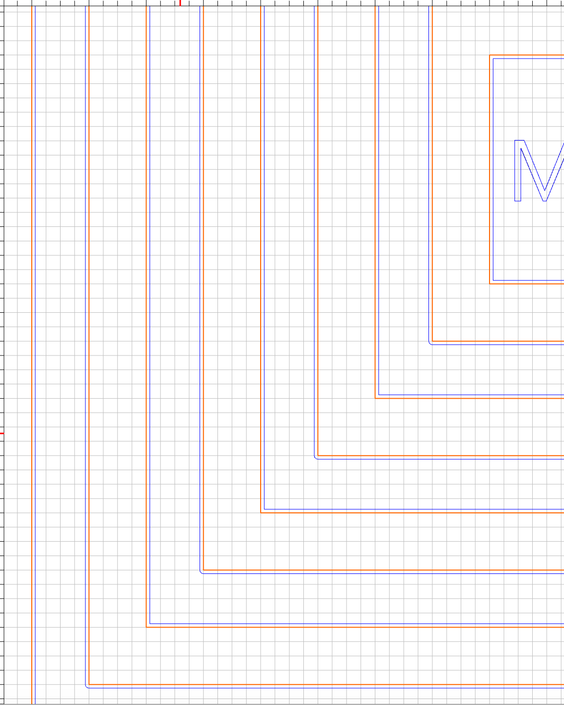
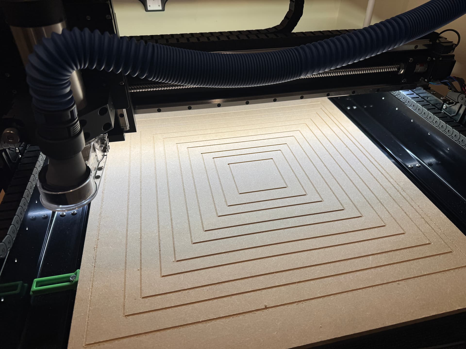
I designed a series of squares 4x4, 6x6, 8x8 and so on in carbide create to be cut into on MDF. The idea was to have perfectly sized and spaced squares for reference. The tool was #102 end mill (1/8") and the max depth was .05".
I selected all the squares at once, chose the Toolpath as contour and offset direction as outside right.. Again, it was one toolpath where all squares are selected so that they would be consistent.
However, when I ran the job, I noticed that the squares were spaced differently and realized that some of the toolpaths, in fact every other square, were actually inside contours (opposite of what I selected)!
This was not expected and does not seem intuitive for design software. Is this a glitch or am I doing something wrong? You can look closely at the file to see what I mean.
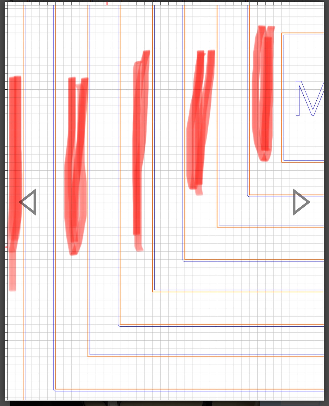
Looks like your tool path is set to cut out separate frames. I highlighted the “frames”. This cuts in the outside of the “frame”. Or, you need to select each line one at a time and choose outside/right” of line.
This is the expected behaviour when you select multiple nested objects. Each time you cross over a boundary, you flip from inside to outside, or vice-versa. The contour path is being applied to the entire selection as a whole, rather than considering each vector independently.
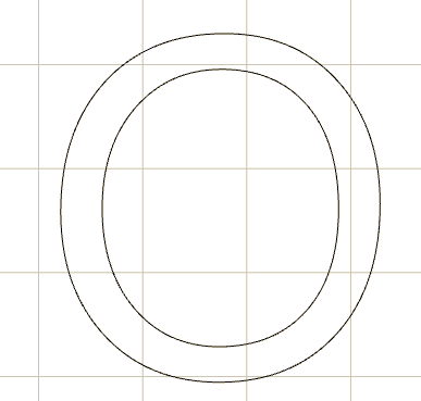
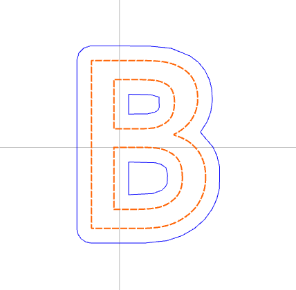
Think of a letter ‘o’. The ‘interior’ of this object is the area between the vectors, so an outside contour can’t be between the vectors.
If you want a single vector to have an ‘outside’ and ‘inside’ the way you want it, you have to select it by itself.
There might be an argument that “If I wanted it to consider all the vectors together, I would have grouped them”, but this runs into the problem that then for most people the behaviour for multi-selected-but-not-grouped wouldn’t match their expectations, even if those expectation are logically inconsistent.
I was expecting all selected lines to use outside, right, so the full square dimensions would be maintained. Some of them changed to inside, but I guess that’s by design?
Read my post and the one from mhotchin, when you select “all” the program assumes you want separate frames and sets up the lines the way you see it.
Select each line separately with “outside right”. Although this will yield a cut part that is equal in width. If this is the desire, then you should just select “no offset” contour as Will describes above.
Here’s a really simple example to show why this is the correct way. Imagine cutting nested vectors in the form of text. If you select the entire letter and want to cut “outside” it, obviously the cutter should not cut inside the letter. When you have pairs of vectors, toolpaths will effectively consider them as a single object. Otherwise anytime you want to cut out a letter or something you’d have to un-intuitively create two separate toolpaths.