Trying to work out improvements for this.
AIUI, Carbide Create has the simplest possible toolpath strategy which has some potential problems:
- plunge along outside edge
- move at constant speed along perimeter
- move in by stepover
- repeat
(I’m considering pockets only to keep this simple)
There’s a bit of a discussion / listing of toolpath strategies at: Complete Guide to CAM Toolpaths and Operations for Milling for reference.
I believe the above technique would fall under “Linear Machining”.
The obvious alternative to the above would be to:
- plunge at the center
- spiral outwards from the center
- repeat
(for a circular pocket — one would need to add a technique for clearing the remaining areas (is there a geometric term for two lines joined by a convex arc?) — I guess arbitrary shapes would require topology which my high school geometry teacher wanted me to study)
I wonder if the above would be improved by:
- plunge at center to depth per pass
- spiral out in an upward climbing motion to half the depth per pass
- do a circle around the perimeter gradually plunging to the depth per pass
- spiral in to the center (possibly reversing the direction of the cut?)
- repeat
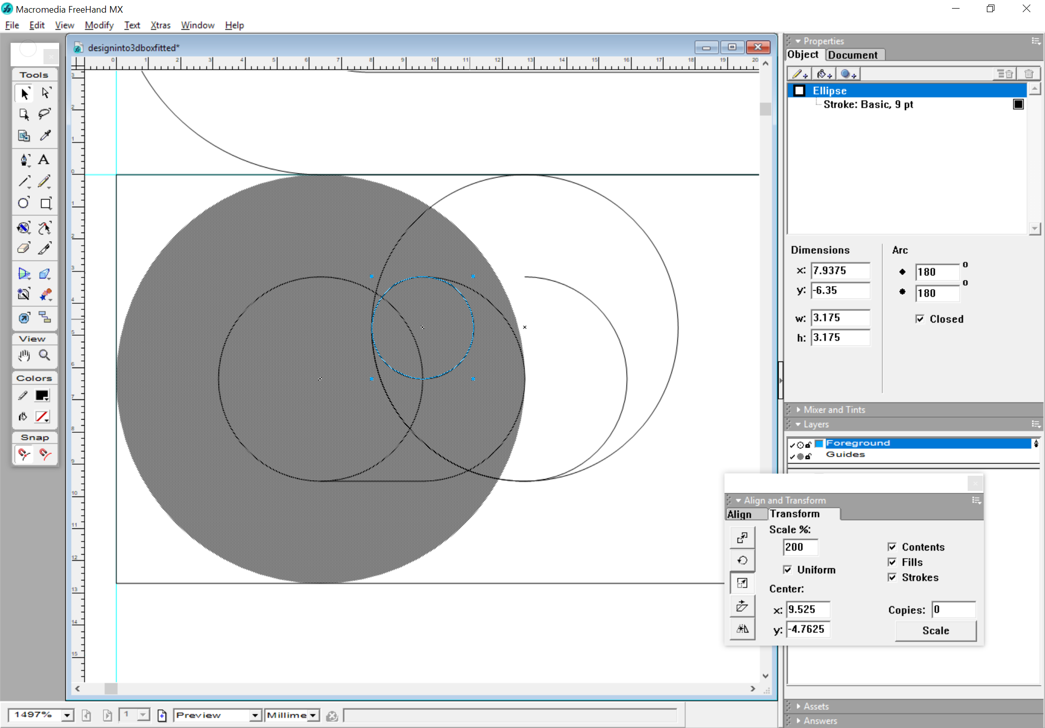
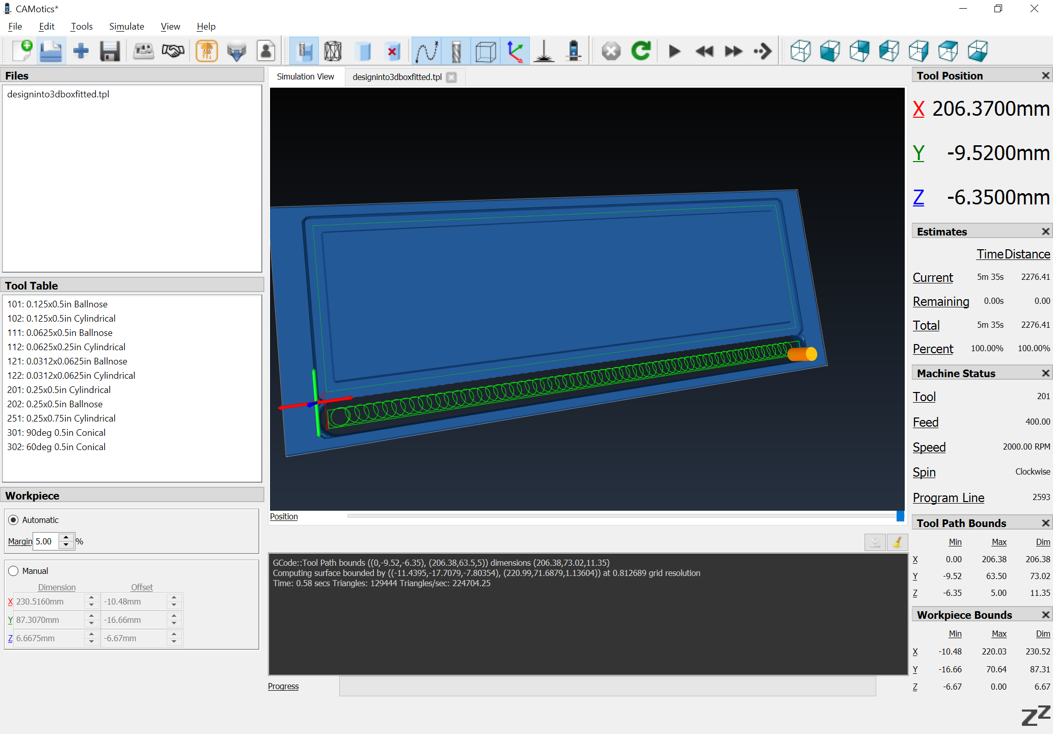
I’m currently working through developing some OpenSCAD modules which will cut out specific shapes (possibly bounded by a ball-nosed endmill) — next will be writing METAPOST macros which describe the equivalent geometry in 2D, then TPL (Tool Path Language) programs to do the actual toolpaths which I’m considering above.
I’ve been reviewing:
- http://mae.engr.ucdavis.edu/~farouki/ijmtm99a.pdf
- http://cam.occ.googlepages.com/curveNC.pdf
- 7 Software Excuses for Bad Surface Finishes - CNCCookbook: Be A Better CNC'er
as well as the links at: https://wiki.shapeoko.com/index.php/CAM#Toolpath_strategies
EDIT: and found this a useful overview:
If anyone has any thoughts or further resources to share, I’d be grateful.
EDIT: Researching a bit more I found:
which notes:
To facilitate high speed machining, a CAM system should:
- Maintain a constant chip load
- Minimize feed rate losses
- Maximize program processing speed
and also notes the desirability of curved/circular movement so as to maintain speed and avoid moving into/out of a corner linearly which slows the machine down (interestingly, exiting at a corner is advocated as one strategy to minimize this).
To frame all of this, I found it somewhat difficult to do the machining on a fitted box:
and had to add roughing clearance and finishing passes — I’m hoping to work up an optimal toolpath strategy which doesn’t require being beholden to Autodesk.
EDIT: a different commercial program, but an opensource plug-in mentioned at: Creating a Trochoidal Slot Milling Toolpath - #5 by siemen - Rhino for Windows - McNeel Forum
and further research on GitHub found:
which seems to be a toolpath option for HeeksCNC — the mention of “freesteel” is interesting — I can recall it coming up as a promising development a while back, but on which work was halted (or transferred to some other project?).
and apparently the FreeCAD folks have been working on this, with images which match my understanding as noted above:
https://forum.freecadweb.org/viewtopic.php?t=30127&start=60
and further images are shown at: Blog - NexGenSolutions (odd shape intended to showcase this technique) and https://v4.e-cam.it/article/60-adaptive-toolpath-strategy (a simple triangle).