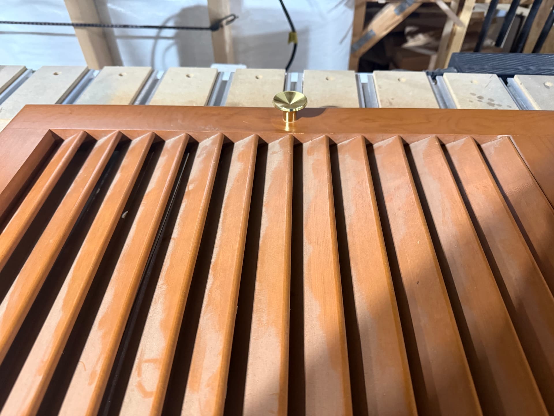
My suggestion is about having multiple zeroing points within a project. I was a machinist in my real job and when getting our jobs programmed properly, we would zero on multiple locating pins. The project that I’m currently working on are doors with slats in them The side rails are 1 1/8" thick and 2 1/4" wide. They will be standing on the 1 1/8" edge in order to pocket for the mortise and slats. With only having one zero point, I’m going to have to be very precise on lining up my stock. It would be nice if I could zero on three or four corners and then working that into the programming. Pictures for a visual referral. Just a suggestion, but I think it could be a huge help for all. Thanks


1 Like
I’ve done many jobs where X an Y had to be inline with machine movement. My solution was to screw down a supplemental waste board to my machines waste board and pocket it out to fit the stock I was cutting. Drop the stock in the pocket, add hold downs, and cut as needed.
6 Likes
Ed, thanks for the idea. I was just going to move “X” from side to side and work from there.
1 Like
GRBL does support multiple work offsets (G54 - G59), so 6 of them.
The problem is CC & CM only use G54 (and G53, the machine coordinates)
So, to make it work you would need to use macros / quick actions to set G55-G59 zeroes, and edit the toolpaths to use them.
That being said, for the job you describe I don’t think you need it. You need to be precise aligning your stock in any event. If you are placing multiple pairs stiles you can make the design match the setup. i.e. if you’re 1 1/8" dimension is slightly off, modify the design to match.
OR, cut each pair separately, and move the Y zero accordingly between each pair.
4 Likes
This topic was automatically closed 30 days after the last reply. New replies are no longer allowed.