Topographic inlay

Ever since I saw the contest from @Radiation at https://community.carbide3d.com/t/community-challenge-28-return-of-challenges/ I wanted to do a design like this using the Carbide Create new inlay feature, but I never got my head around how to do this in time for the contest… but better late than never.

(note: although I show some of the steps below, this is no a tutorial. While I normally show a lot of the digital steps in great detail when I write tutorials… this one is different. If this were youtube, I’d ask you to put in the comments where I cheated and skipped some complicated things… oh and to like and subscribe of course)

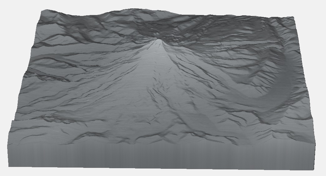
Things start of course with getting an STL file of the desired region from touchterrain, in my case the Mount Hood vulcano.

Then, make a simple 3D model in Carbide Create Pro, add roughing and finishing toolpaths


roughing

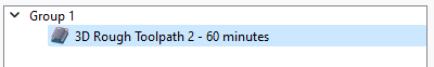
Wait. 60 minutes for roughing?? No way is that what I want.

[Opens F&S calculator. Measures cut length of bit #201. Watch TitansofCNC on youtube. Maximize chipload. Digital Banging Noises]

screenshotroughing2

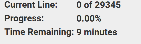
9 minutes. That’s more reasonable.


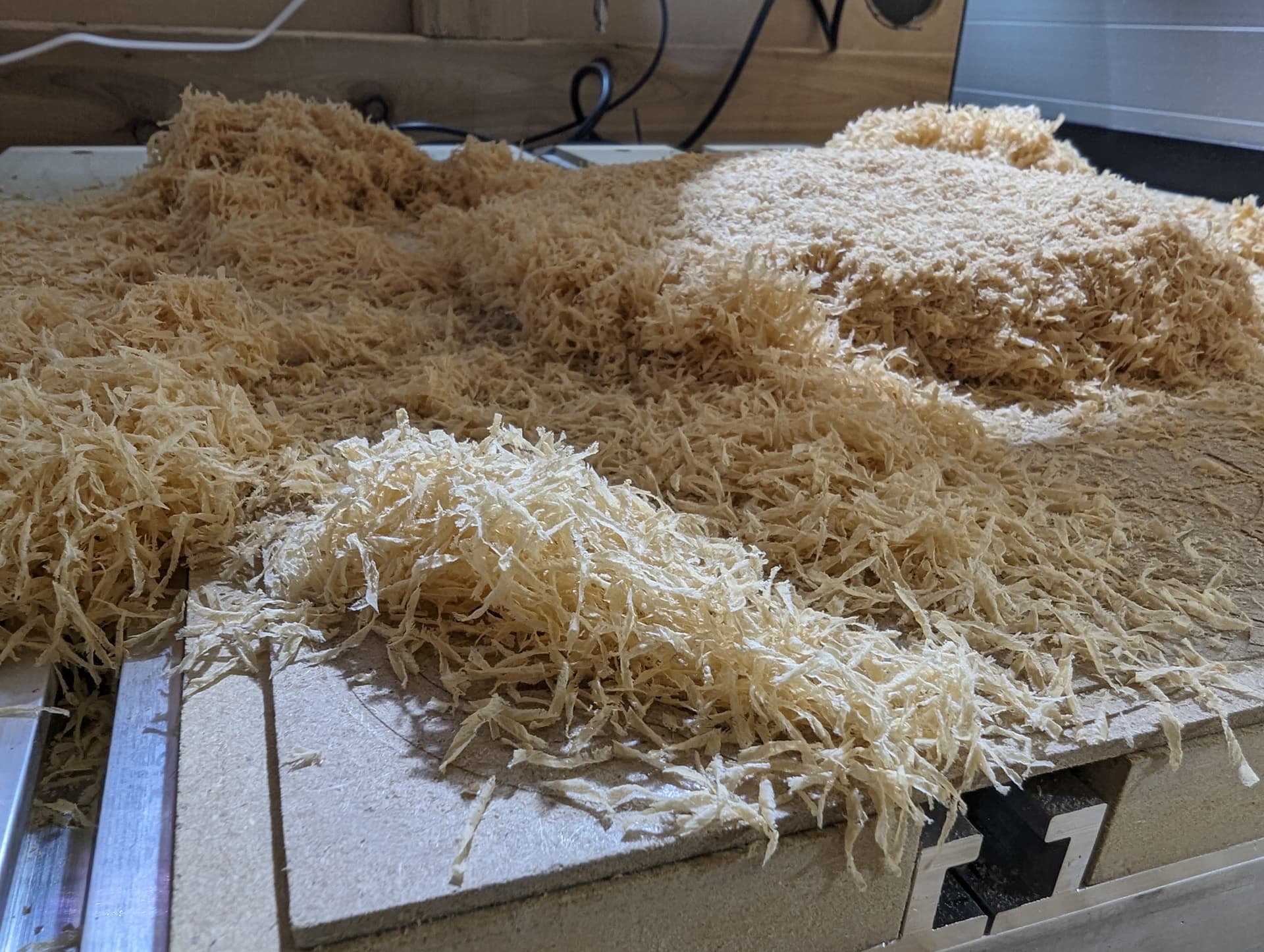
It gave nice chips but my dust collection did not manage to keep up.

As a video: Base Roughing - YouTube
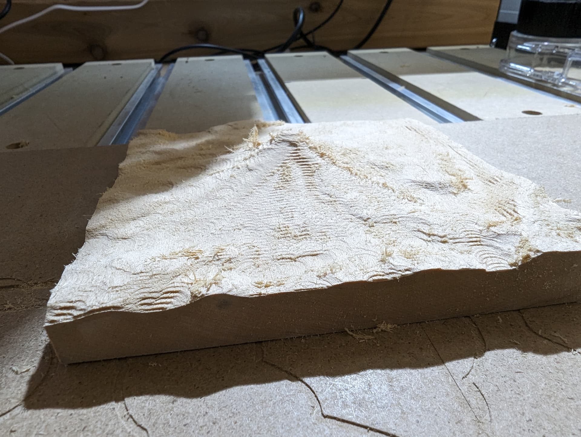
And the result:


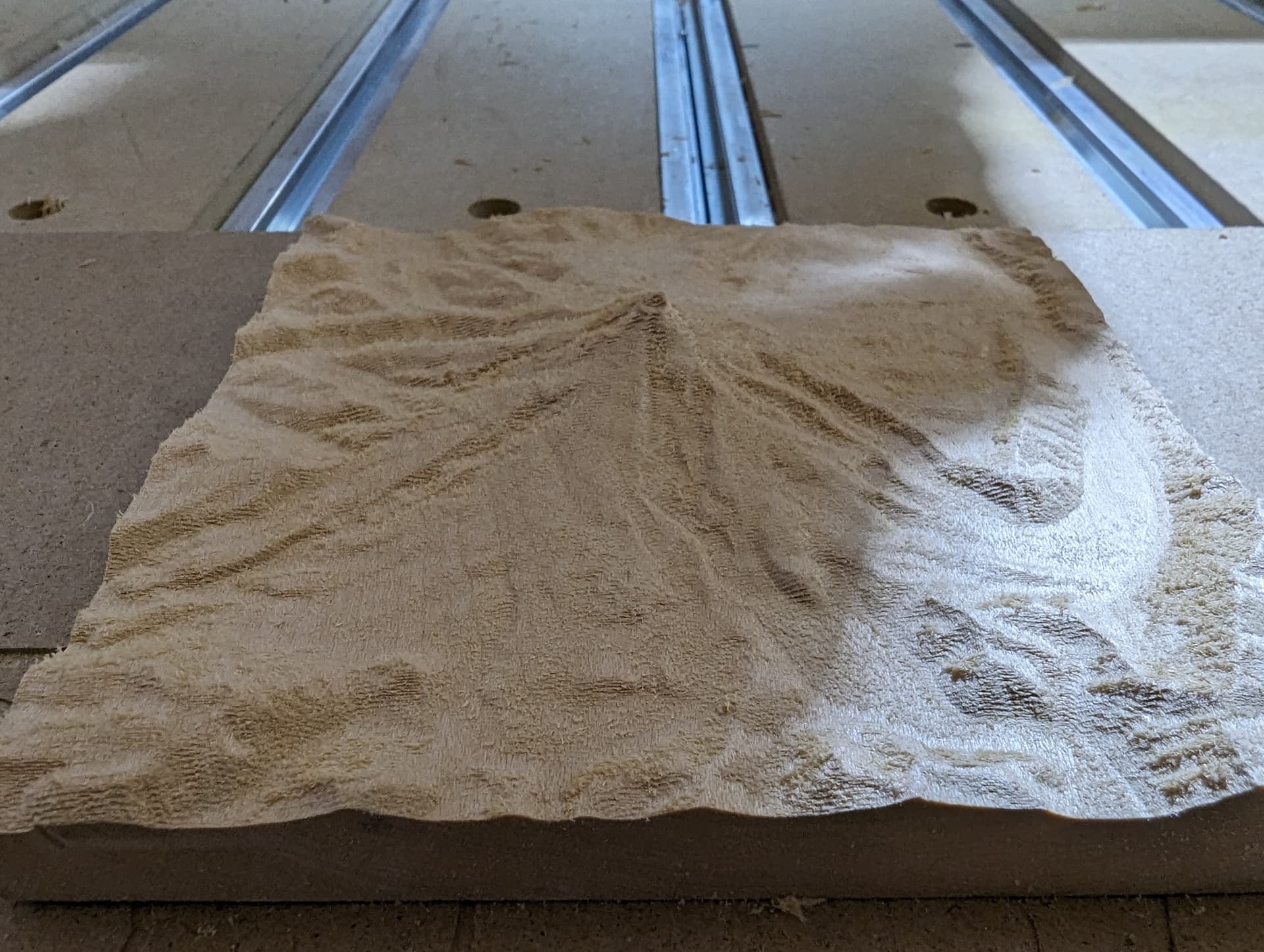
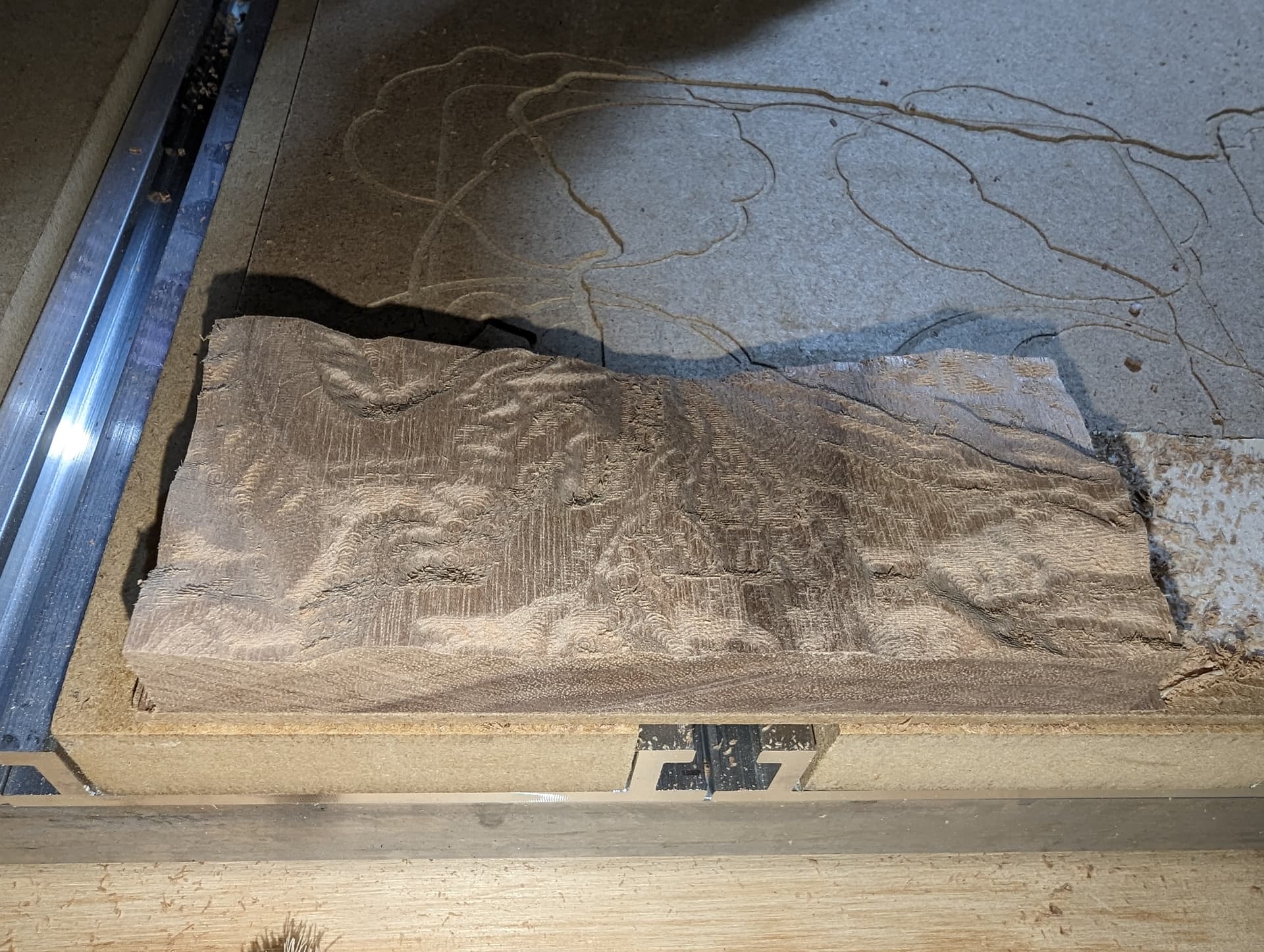
And after an hour of watching my machine zig-zag using a 2mm flat endmill:

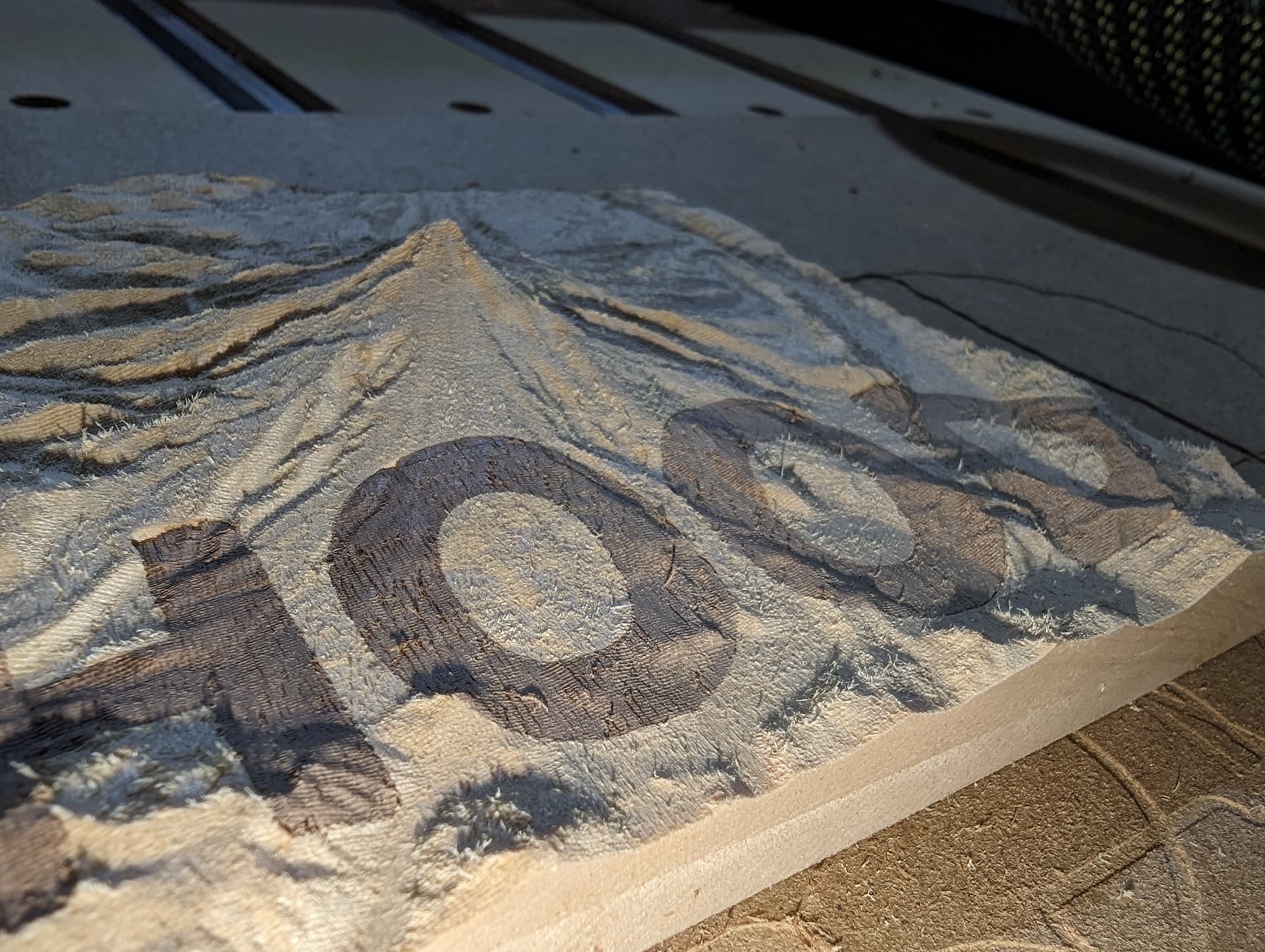
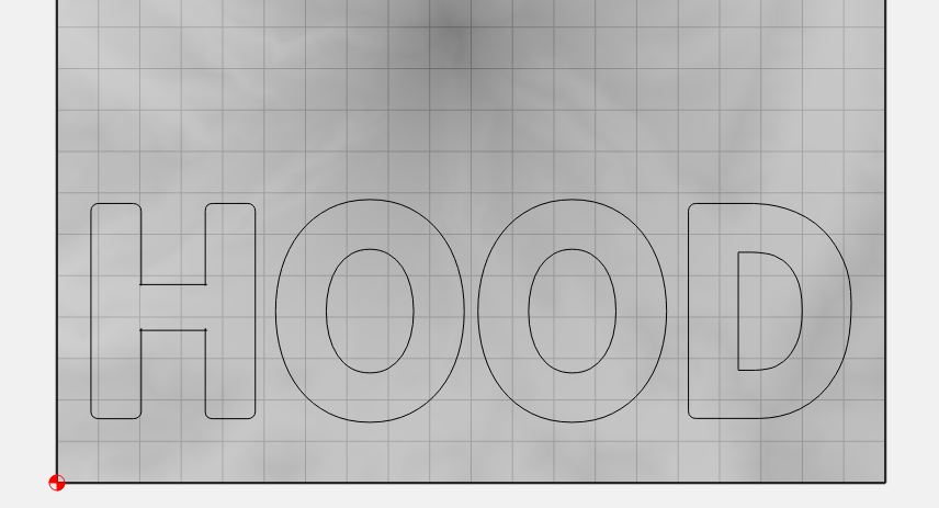
Ok that’s the topography done, now on to the inlay… Just a simple bit of text.


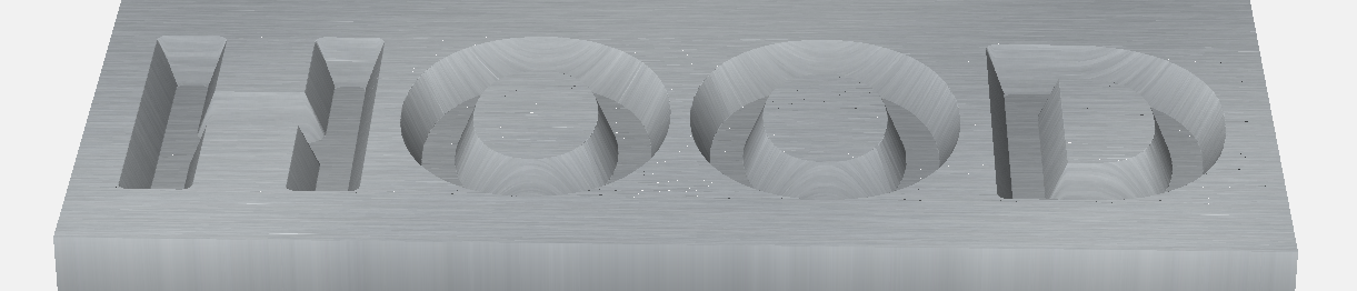
The preview looks good so lets carve it into the topography:

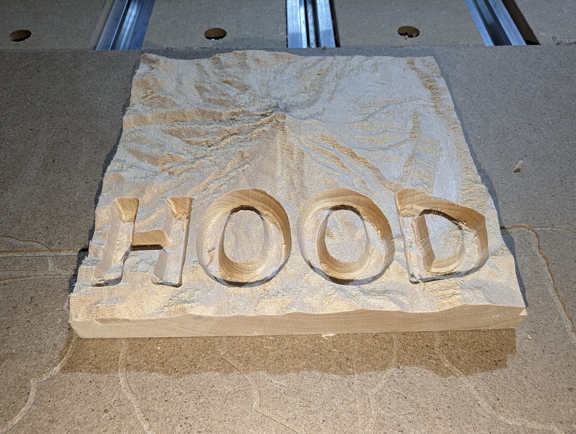
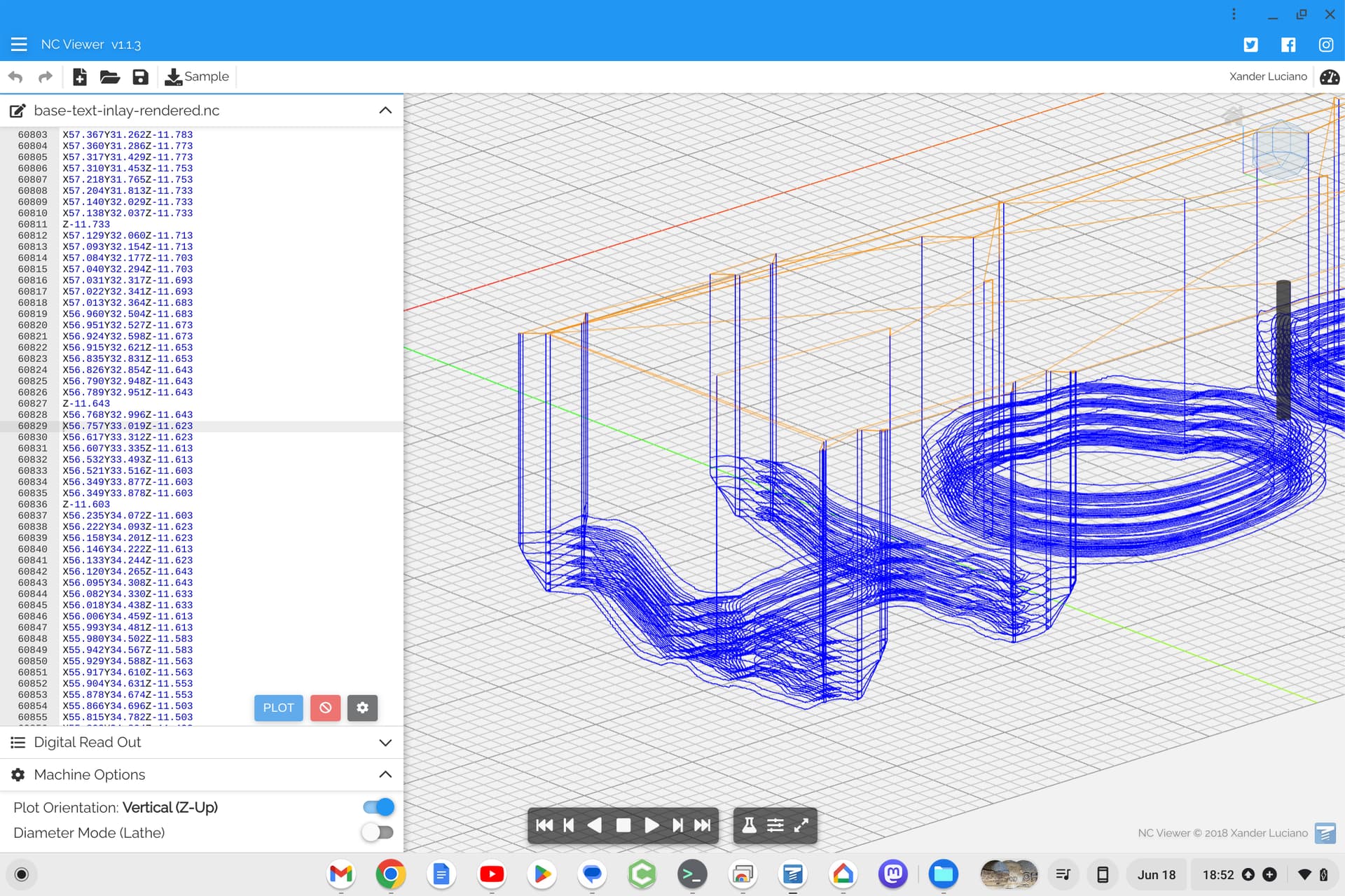
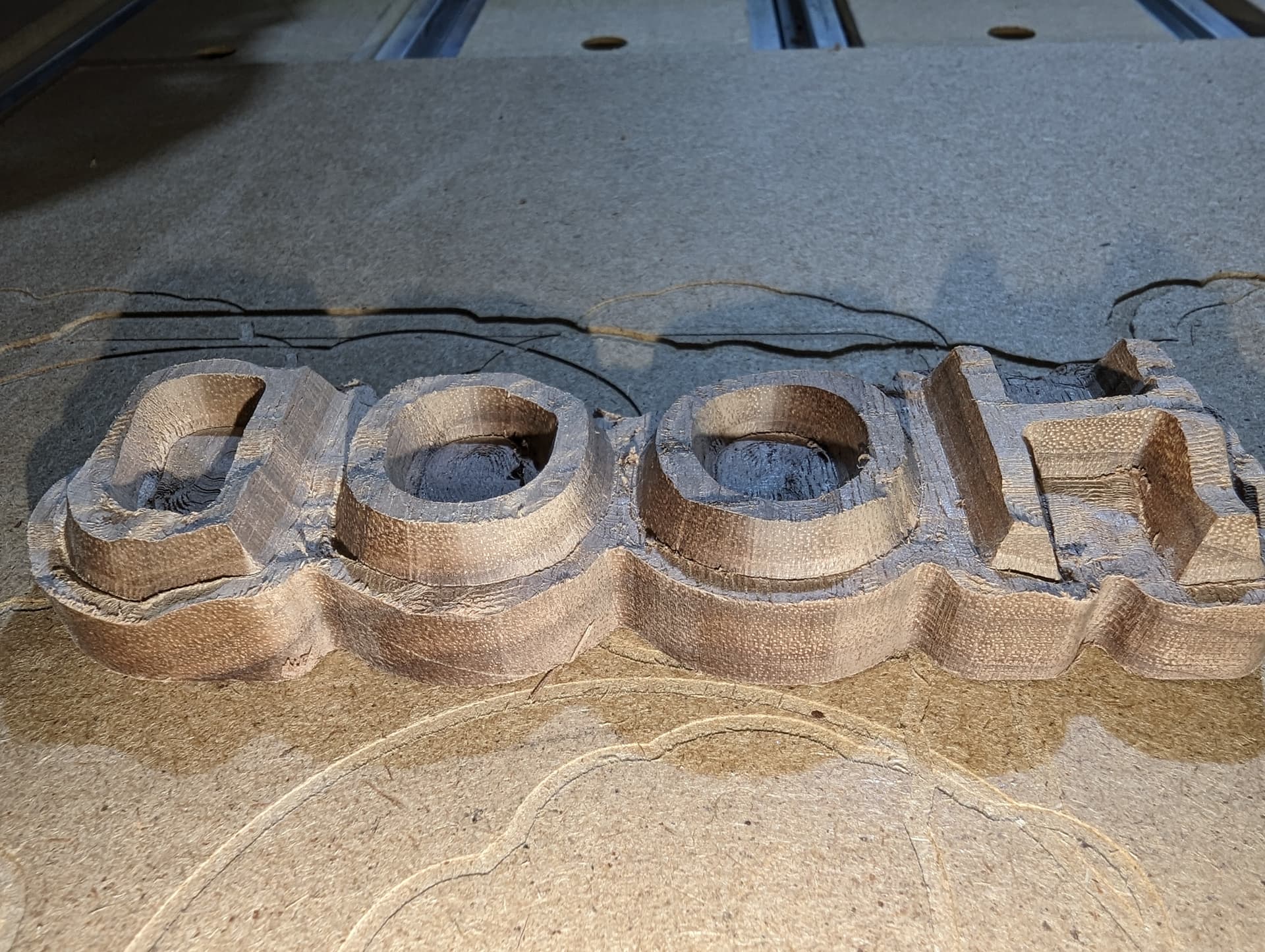
So on to the plug… lets not forget to mirror the design:


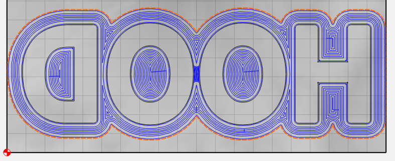
looking good… lets cut it

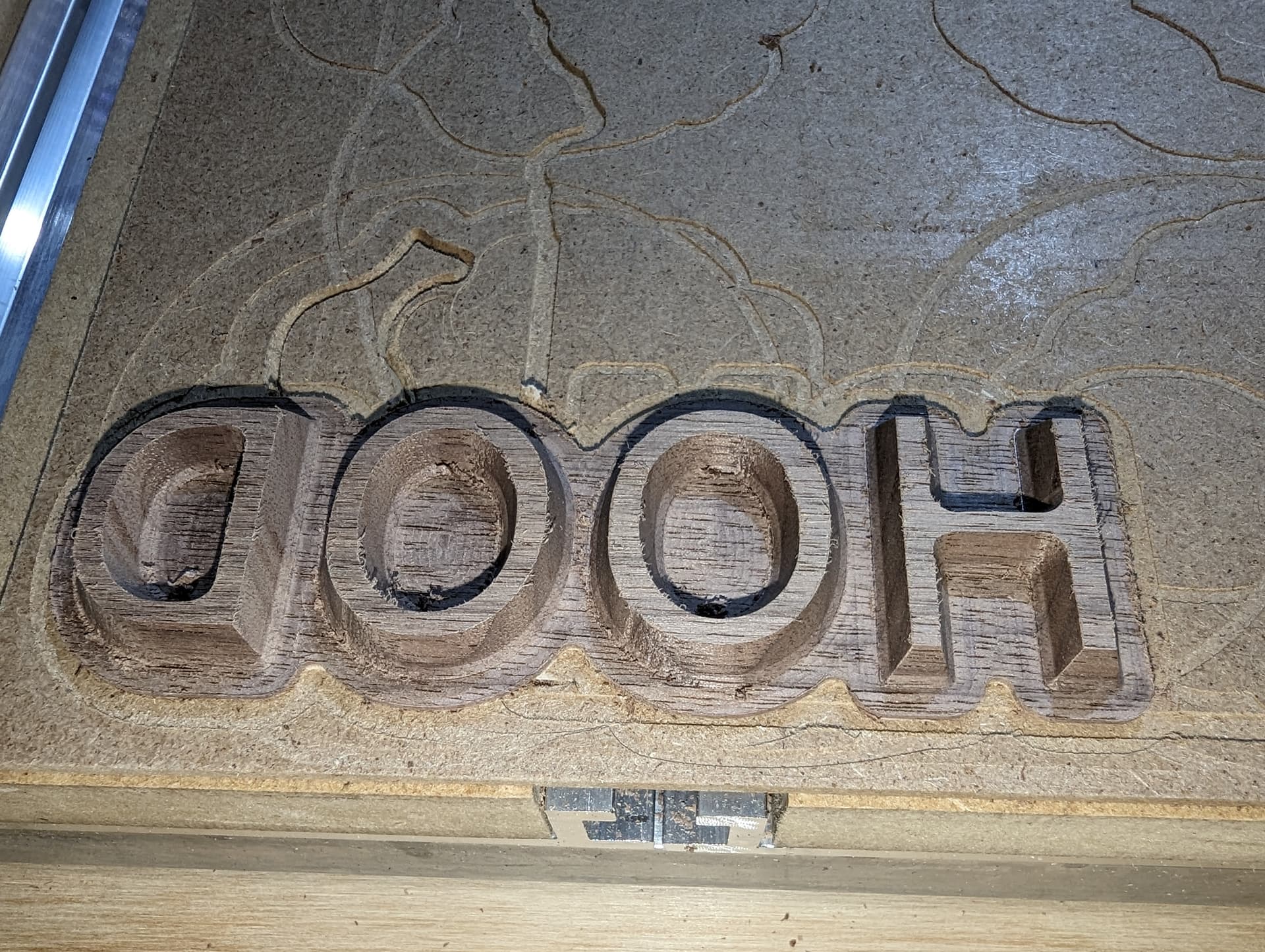
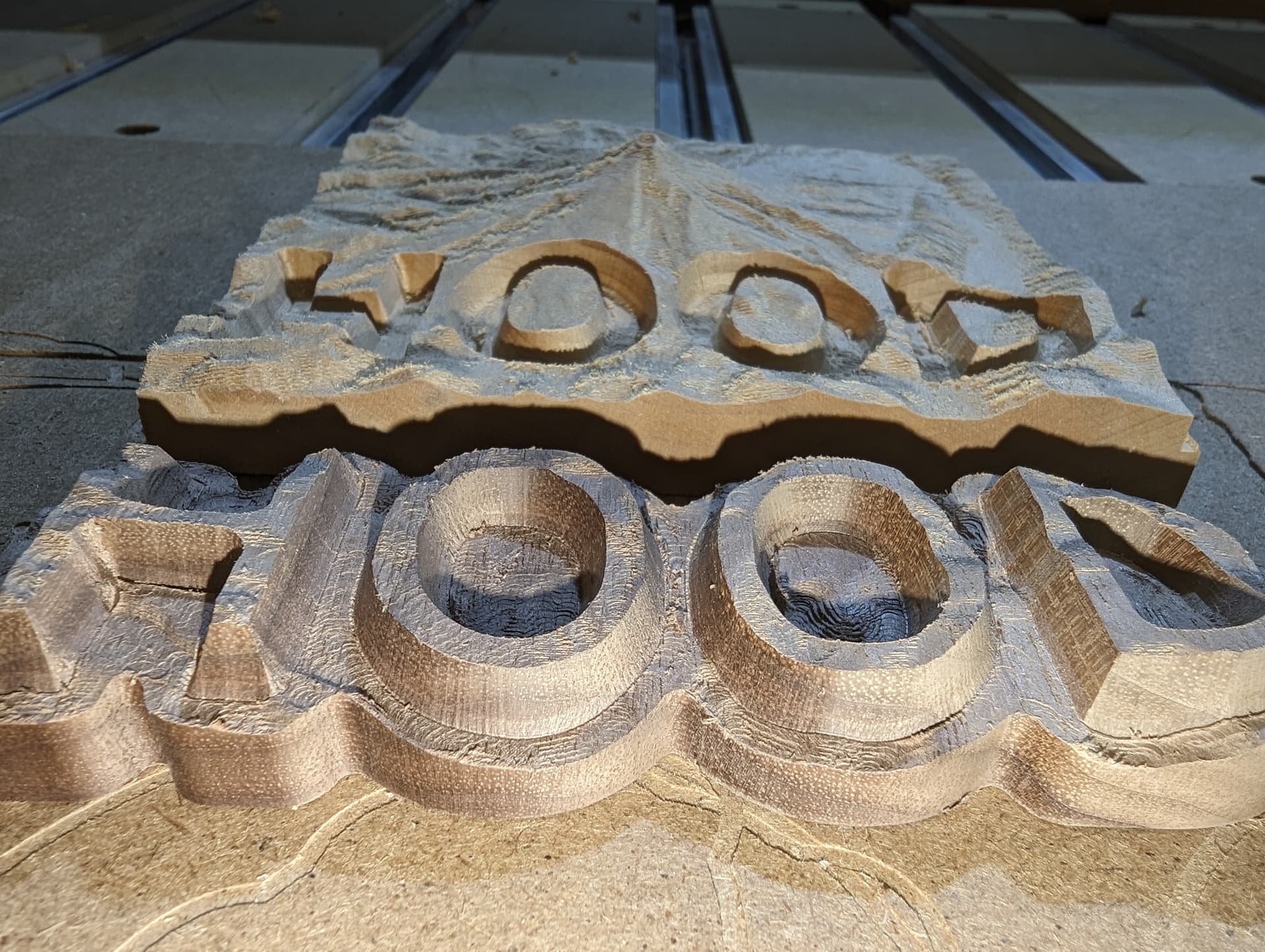
eh. rookie mistake, that’s not going to fit in the gap in the base.

[Cursing sounds. Digital banging noises. Pixie dust]

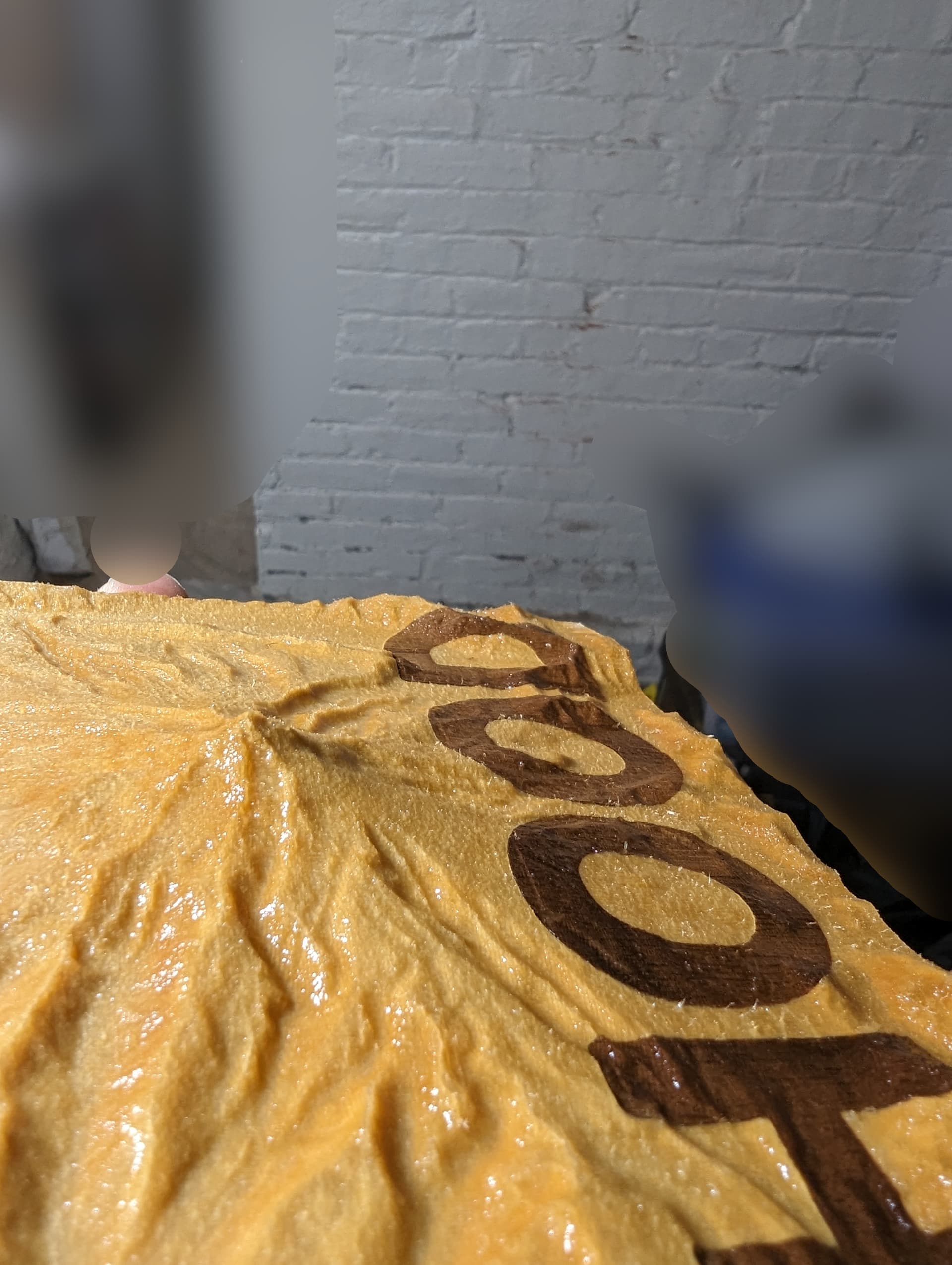
One first needs to cut the mirrored inverse of the base landscape

and THEN cut the plug toolpath on top of that

There. Much better.
This looks like it’s going to fit:


So time for the glue-up:

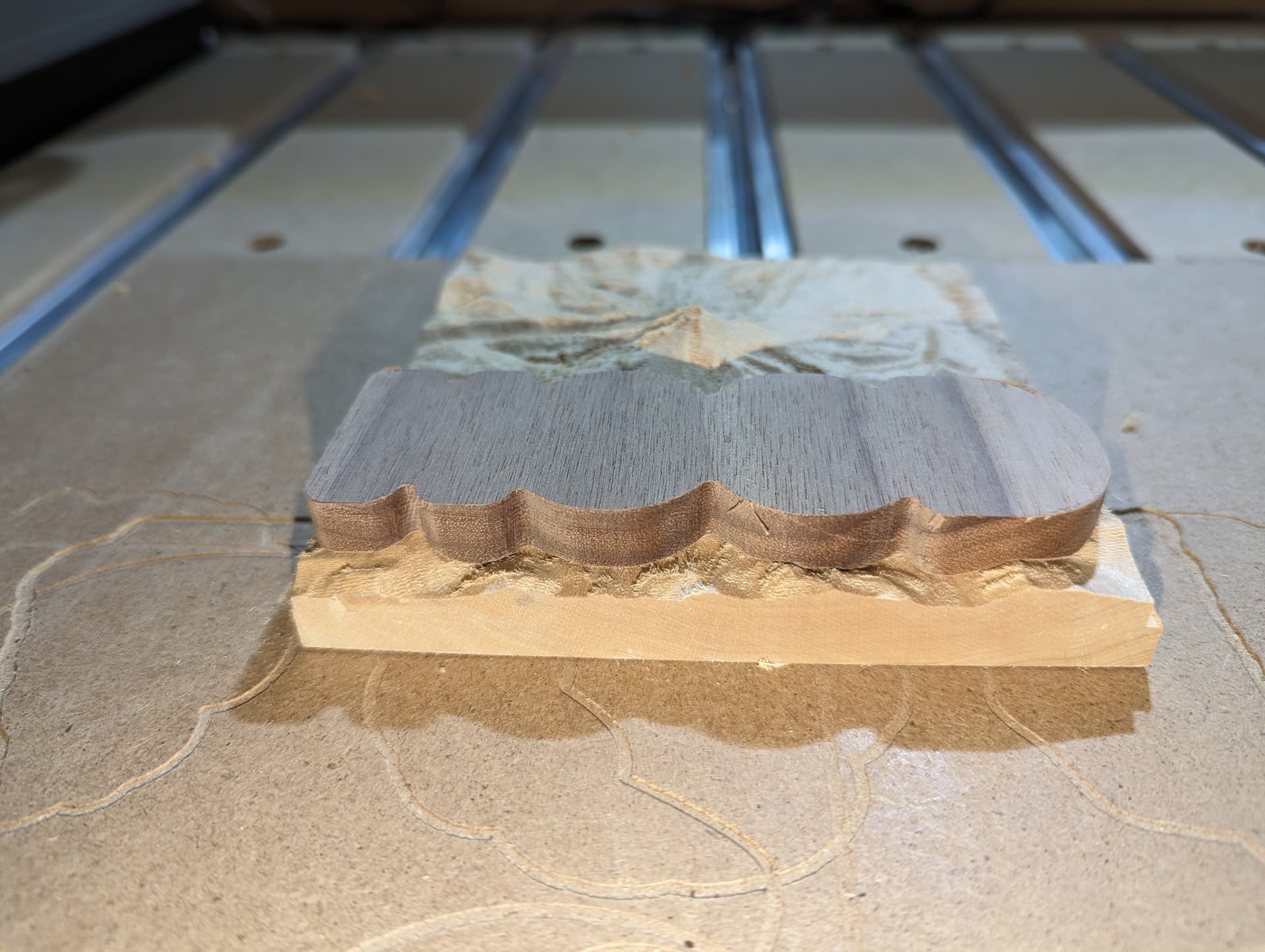
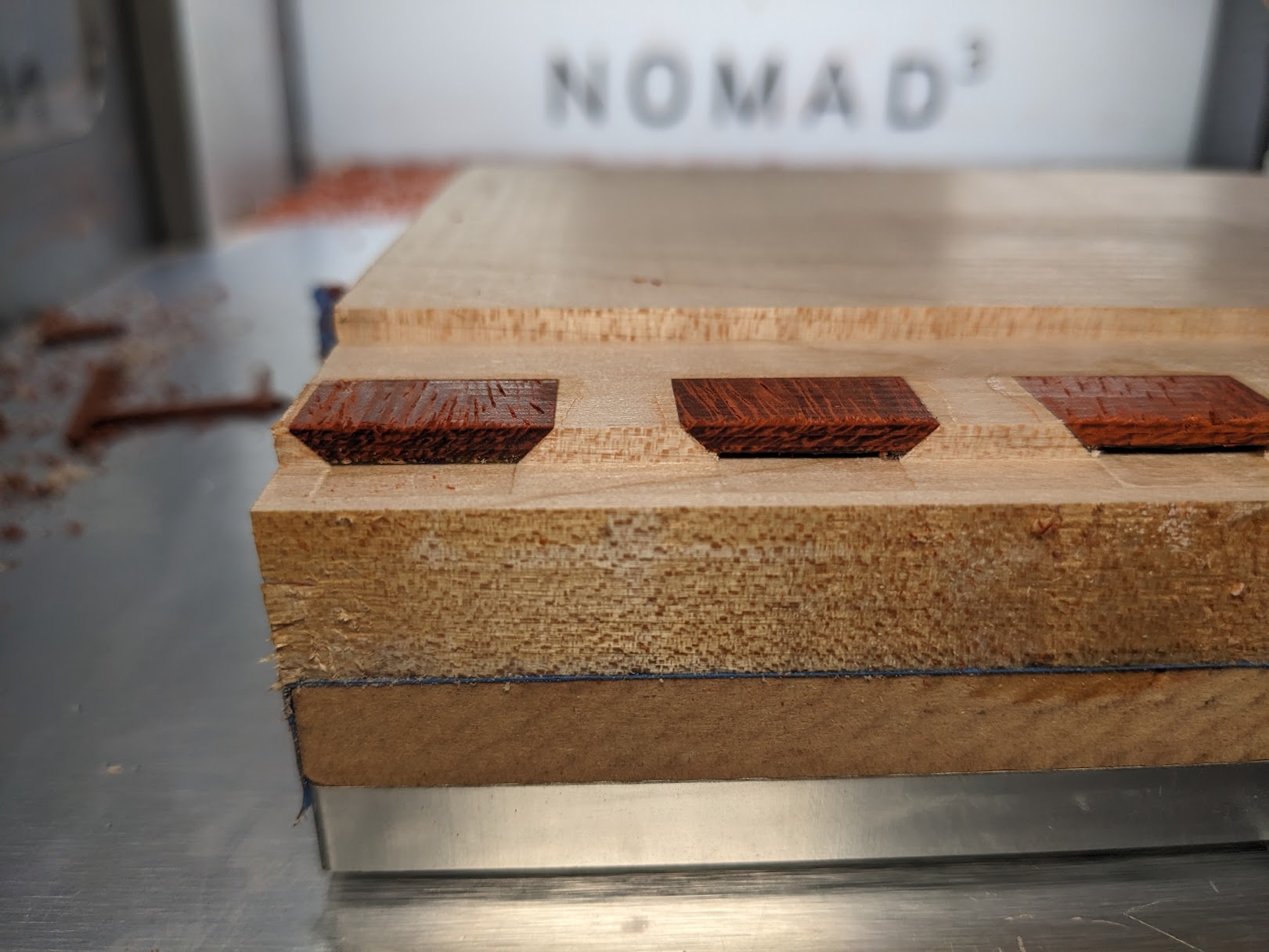
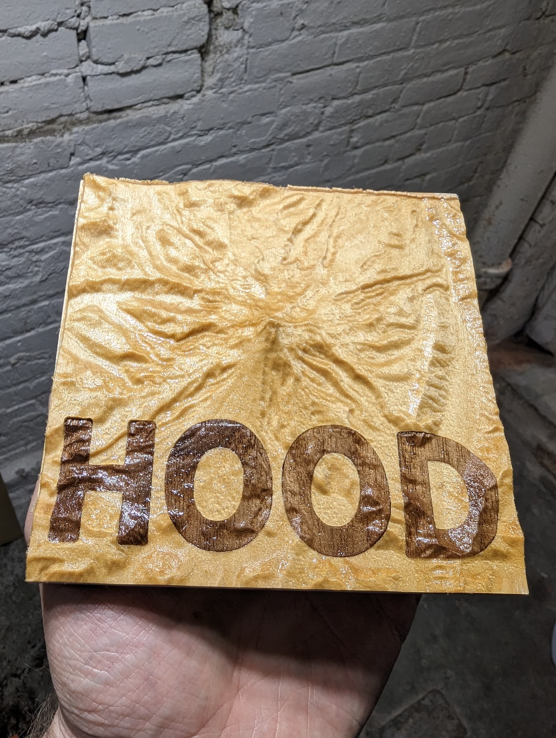
And after cutting off the top

[edit: the picture below is after I redid the cut with a 20 degree V bit]

9 Likes

I wonder what it would work like if you did the inlay first and then the 3d carve.

3 Likes

It’d be tons simpler.

But mapping the carbide create toolpaths for the flat inlay onto the 3D model of the base was the fun digital part )

what I mean by “mapping” is maybe best shown in a picture (below); the base “flat” pocket is modified to “follow the terrain”

4 Likes

I don’t know what artistic effect you’re trying to achieve with the giant “HOOD” part, but I don’t get it. Perhaps when you perform some finishing magic it will become clear?

sorry for the delay but I decided I had to re-cut this with a 20 degree bit to get rid of the nasty gaps in the fit

The effect I was after is to have the inlay being completely normal part of the terrain, e.g. all the bumps and rivers etc are all completely there independent of which of the two pieces of wood are there:

6 Likes

For the folks who wonder “why can’t you just do the inlay first straight up and then cut the terrain”… think of it this way: You make the letters with a V bit, which means that the width of the font depends on the depth… but depth varies with the terrain so if you would this the (too) simple way, the width of the letters would be super wavey…

3 Likes

I’ve been kinda playing around with inlay to get rid of a gap. So far sizing up the plug image by ~.5mm or a mm gets a better fit on some shapes.
I also use about a .5mm gap.

I bring this up, because if you do it that simple way, I think you’ll find that the inlay should basically be along the entire depth of the carve:

sure but if the depth at the top varies (as terrain does)… the width as seen from above will also vary…

if it’s letters that will look not so nice i suspect

the gap comment reminds me that i still need to build a simulator that takes the two gcodes and verifies the fit, to rule out any digital bugs

4 Likes

I guess my thought is that you could do a deep v-carve/plug and then the topo. But sometimes the more challenging ways net some neat results, so good luck!

I have been experimenting with using CAMotics to write out an STL from the 3D simulation of G-code files, then compositing the two files of an inlay — sending you a PM with the link.

A deep inlay is obviously much simpler than the (waaaay too) complicated steps I did.
But the result is not the same.
Take a square that you inlay with the goal of looking square
if you’d look from the top it looks like this


with the outer square being at the zero level of your material, and the inner square being the bottom of the inlay. If you were to cut material from the top (say topography), you get a depth-dependent demarcation between base and plug somewhere between the two squares.
For example it could be this

for some irregular landscape. For shapes where the human eye doesn’t care as much about being perfectly parallel that can be just fine. But for text … maybe not

But it could also be this in the extreme (yeah I know, square peg round hole)


Sure this one is a bit tongue-in-cheek because it takes it to the extreme :wink:

The process I followed will give you the outer square at the exact depth of the terrain, with the 2 pairs of sides being perfectly parallel and square… much more work but that was the result (but in text) I was trying to get.

Would I do it again? Probably not… lots of steps for a simple ending result

5 Likes

This is great work and came out really nice. I would love to start experimenting with something similar to this and was also inspired by the topo contest. Still trying to wrap my head around why you can’t do the inlay flat first and then the 3d carve. I think I see your point, but I’d still like to see someone do a test!

This topic was automatically closed 30 days after the last reply. New replies are no longer allowed.