Depends which way you’re out of square…
I decided that it was best to tram the whole Z assembly wherever possible as I would like the cutter and the Z movement axis to be aligned.
When I fitted my HDZ, before putting the spindle mount on I used an engineers square to check whether the Z axis was normal to the spoilboard front / back, i.e. whether the X axis beam was rotated, it was so I loosened off the bolts on both ends of the X axis and rotated the beam in the Y gantry plates until I was vertical, seemed to me to be easiest to tram the X beam vertical and work from there rather than fudge the Z axis as I want Z plunge to be vertical, not on some nasty angle.
I then made the same check on the side of the HDZ travelling plate the spindle bracket bolts to, I found no offset here, if there was my plan was to loosen and fudge about with the two upper V-wheel carrier bolts above the X axis.
Then I bolted on the big chunky spindle bracket from Carbide that I got with the HDZ, I made the assumption that the sides of this were parallel to the spindle axis once mounted and used the same square to check if the bracket was on square, I discovered there was a small amount of movement available, got it square and tightened it up.
I made a cheap spindle tramming tool for my dial indicator a while ago, a piece of 8mm rod and a stick basically to go in the spindle collet;
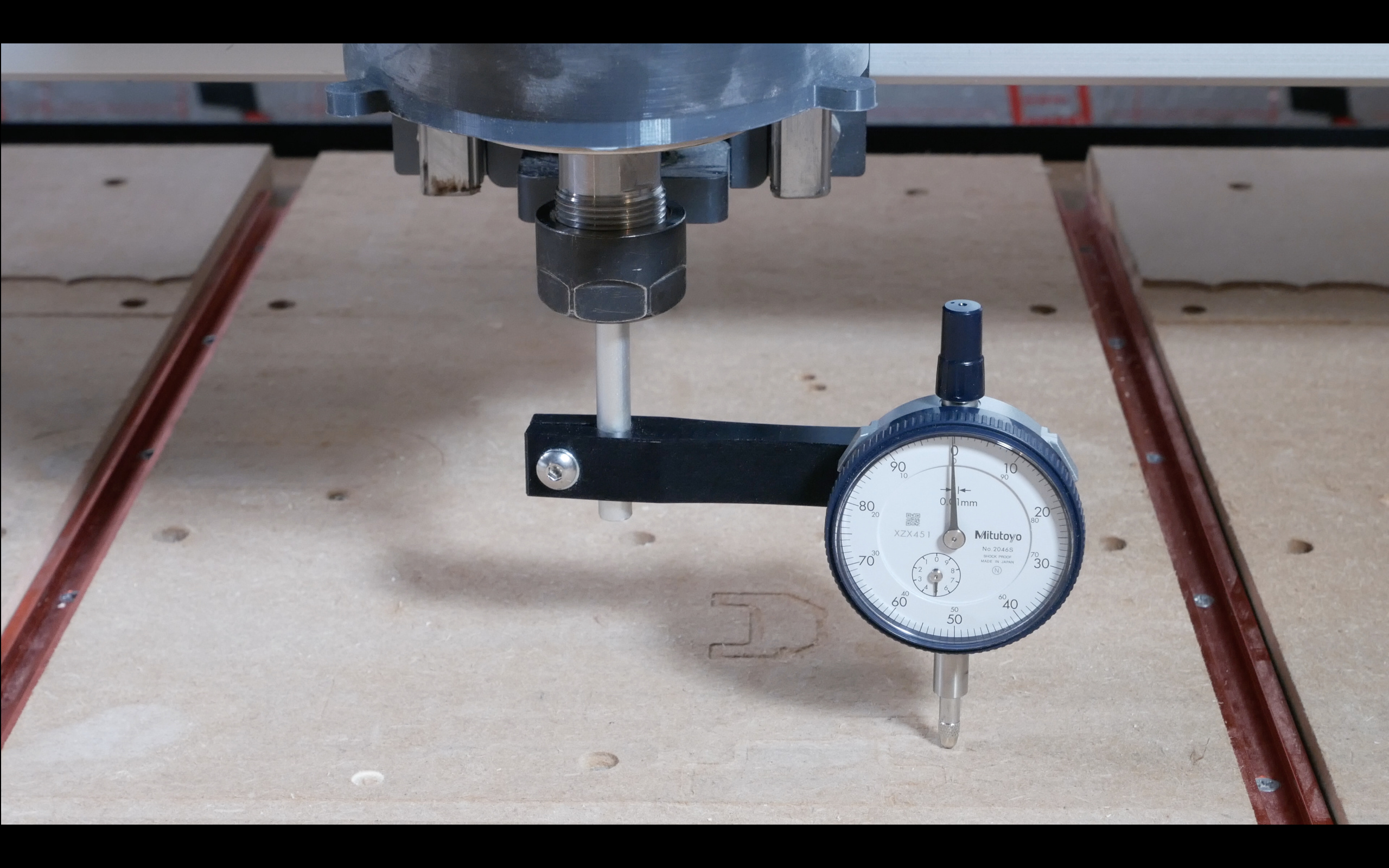
As described by lots of other people I got the idea from, it doesn’t need to be square or anything else, you rotate the spindle (by hand…) and check the dial to see if the spindle rotation axis is normal to the spoilboard.
I’m sure there’s other ways and opportunities I didn’t spot but this got my particular set of misalignments straight enough for woodwork.