I have a XXL 4 and I have trammed my machine before but it takes forever to dial it in exactly, just for it to work itself out of kilter within a few days. Is there a modification that you can do to X-plane (or Y if that is even possible) of the router mount to either make it easier to micro adjust or to hold it from moving. If I tried to tram it as often as it probably needs I would never get anything done. I am a wood worker, not a machinist, so please keep that in mind when you are giving me ideas.
What is your machine sitting on? Does it have casters? Do you move it around a lot?
Update with a picture of your machine and what it is sitting on. The tramming of the router should be good for a long time if you got it correct the first time. On the SO4 the left and right are controlled by eccentric nuts. The forward to back is done with shims behind the router mount.
I use 123 setup blocks to get my router trammed to the bed. You can use dial gauges and various other methods to get the router trammed with the spoilboard. Then after you get your router trammed you need to flatten your spoilboard.
So for both the tramming and the flattening to work properly you need a stable base for the Shapeoko to sit on. If your base is not stable your tram will fluctuate and you will continue to chase your tail. Round and Round but never quite catching it.
I can’t provide pics until later today, but it is on a solid platform that I built for it. It is flat on the floor with no casters.
1 Like
I use a dual dial gauge. the first time I did it, I flattened the spoil board surface but then realized when I try to do oversized signs that extend out the front and back of my machine, I had created a lip that would not allow my board to lay flat on the spoil board. So this time I have tried to tram it to the spoil board surface without leveling the surface as to not create a lip edge outside the cuttable area.
I question whether this insures that the motion of the Z axis is perpendicular to the XY plane of motion.
I shim the entire Z axis assembly, rather than just the motor mount.
Where do you shim the entire z axis? I am only a CNC’r for a year now. Have learned a lot but probably just enough to be dangerous. haha

How do you micro adjust the XY axis? Seems like every time I get it right, it moves on me as you start to tighten everything back down. You end up chasing “0” by over compensating the other direction in hopes of it hitting “0” once you tighten it up. Frustrating process sometimes.
A hammer is one of the most precise adjustment tools. As you are getting closer snug up your bolts just a little and subsequent taps will move the spindle less. I’ve got a couple different sizes with plastic faces of different durometers for the router, and a copper & brass one for the bigger cast iron machines.
Not quite sure what you mean. The previous picture shows how I adjust the Z axis from front to back. You also have a little bit of adjustment side to side, but not much. So there you have to compromise & adjust the motor mount.
For the green adjustment above, if my tramming device (indicator mounted in the spindle) has a 10" diameter, and it’s off by 0.006", and my Z axis mount is 6", then I need to shim it 0.0036". If it’s still slightly off after that, I interpolate. i.e. If it’s still 0.001" off, I’ll bump the shim up up 0.004". When it’s less than 0.001" over 10", I’m happy.
For side to side, I zero my indicator on the low side, move to the high side, loosen very slightly 3 of the 4 mounting screws & tap the motor mount until half the deviation reads on the indicator. Then swing the indicator around & repeat the process until it’s also within 0.001" over 10". If I have no play in the motor mount, I tight the opposite screw & loosen the one that was tight before.
Everything Tenacious D said. I would only add, start at the floor and work your way up. All four legs are in contact with the floor and all have equal weight on them. Table top is level and flat. Any bow or twist will be transferred to your machine base and this will make Tramming the head very difficult.
2 Likes
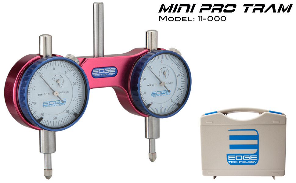
I appreciate all the input. I was on the right track, short of shimming the Z axis assembly instead of the motor mount. I am using an Edge dual gauge tram to do this process. It is 3" between dials, so can you share with me the formula you are using (Tod) to get your shim calculations. I followed the one when it’s 10" but don’t know what it does to the process of calculating when the diameter changes. Sorry not a mathematician either. I can do and follow formulas but just don’t have the brain power to reverse engineer that process to figure out what changes. haha.
Distance between gauges / difference between gauges = distance between shims / shim thickness
OR
Shim Thickness = Distance between shims * difference between gauges / distance between gauges
My Z axis mount is actually 9", so using your indicator if it’s off by 0.005", I would use
Shim = 9 * 0.005 / 3" = 0.015"
I have 3 bolts from top to bottom so I’d put a 0.015 shim at the top (or bottom), and a 0.0075 shim in the middle to prevent the mount plate from bowing at all.
3 Likes
This topic was automatically closed after 30 days. New replies are no longer allowed.