Tramming/surfacing issues

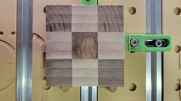
So here’s the situation. I’ve been playing with end grain inlays and there are very prominent horizontal lines from using my 1" McFly to surface the board. Obviously I needed to tram the machine.

I proceeded thusly:

  1. Surface spoil board (-0.015").

  2. Place a pain of glass on freshly surfaced spoil board.

  3. Use dial indicator to ensure glass surface was flat.

  4. Place dial indicator inline with Y axis and shim the spindle mount until it was flat front/back. I used a 0.0015" feeler gauge as a shim.

  5. Rotated dial indicator inline with X axis and used the “hammer” method to tram left/right axis.

  6. CELEBRATION!

  7. Surface spoil board again (-0.015"), noticed some subtle lines along the X axis.

  8. Mild panic.

  9. Get a small piece of end grain and surface that.

  10. Cry…

So I proceed to check the tram again using same procedure as before. I set my pain of glass near the front right side of the machine and check the tram front/back. My dials indicate a difference on .004". So I move the glass to the back left of the machine and dials indicate .012" difference from front to back.

What am I missing here. Why would the machine become out of tram so quickly? Why would tram be different in different areas? Is 0.012" really not the big of a deal? Is something else afoot?

Speeds and feeds for 1" McFly: Feed rate: 200 IPM, RPM 14,000, DOC 0.015". After the first pass on the scrap end grain I switched to a brand new Whiteside 6210 1" surfacing bit. Same speeds and feeds. This is the dial indicator I used.

Thanks again!
1 Like

It appears as if your machine has not been trammed. If your image is the right way up for north/south, your spindle is tilted forward at the top end. Your calibration method (hammer) appears to be disappointingly inaccurate. 0.015" is just under 0.4mm and I would not consider that amount of difference in edge to edge slope as level. the 0.006" in difference is what is responsible for your tram lines on your photographed test piece. I would aim for 0.0005" deflection of your tram gauge in X and Y directions. I have delineated the process I use below, which works for me. I see no reason it would not work for you if you calibrate the tramming tool more accurately

I wondered if your calibration method was responsible. My tram gauge is the Edge Pro which is marked with divisions that are 0.001" apart and uses a ¼" shank. Crucially, the repeatability is specified as being 0.0002" so one can have confidence when taking serial readings. The tool you linked ought to be much better than mine with its ½" shank and 0.0005" divisions. Despite searching the SST specifications, I see no mention of the repeatability parameter.

I calibrate my tramming tool by using a 10mm thick piece of hardened and armoured float glass that is 300mm square. Edge provide a calibration steel gauge that is placed under one dial gauge and after lowering the gauge by a half revolution on the dial, it is zeroed. The calibration steel is placed under the second dial gauge after rotation of the instrument through 180°. The second dial is calibrated using the same method as the first. After calibration and although the divisions are marked 0.001" apart, I use the stepper motor on the z axis to decend to just one full revolution of the dial gauges and the indicator sits on the zero mark precisely and when one dial gauge sits at zero, the reading is reflected on the second dial.

My tramming process is to run the paired calibrated gauges across the glass in the Y direction at the top, middle and bottom edge of the glass. I note the deflection readings and keep the indicator needles to within no more than a ±0.0005" deviation when moving the gauges in the Y direction. I then do the same for the X direction. During this time, all the securing bolts of the spindle (4) are very slightly loosened. This means that a firm push will produce a very slight deflection of the indicator needle. When the readings approach the accuracy I seek, the bolts are tightened in an equal but sequential pattern with a torque wrench set to 15Nm.

Your issue will be resolved by shimming the Z axis. When you feel the ridges going across if it is higher in the back then shim the bottom of the Z. If the ridges are in the front then shim the top of the Z. You can use paper or folded up Aluminum foil. It does not take much because of the length of the router and bit sticking out.

If the ridges were on the sides then just adjust the eccentrics on the Z.

Just loosen the Z enough to get your shims in and retighten and retest. When you get the machines properly trammed then surface one more time. The T-tracks are considerable lower than the surface of the spoilboard but make sure previous surfacing does not have the spoilboard so low you hit the tops of your t-track.

Before doing any tramming make sure your machine is square and all bolts are tightened. You will waste your time tramming if the machine is not square and all bolts are tight because you will get inconsistent results.

Back when I trammed my waste board I did it the hard manual way. (not having a dial indicator.

I used a board 12 inches long, 2 inches wide and 0.75 thick.
I drilled 1/4 holes in the 0.75 side, opposing ends and sides as in the picture below.

Traming board
I placed one 1/4" bit in each hole firmly. Placed it in the collet of the router and raised it till the lowest part of the rotation of this tool touched the waste board. I used tinfoil where I needed or moved the angle of the router I could, to bring the router to an even touching of the waste board while rotating the tool in the router.

I have a tendency as to not explain myself well. (Sorry)

If you have questions feel free to ask. I’ll try to answer better.

Unless you bought special glass that is guaranteed flat then that could be part of the problem. You can use glass that is intended and a backing for sharpening chisels.

I bought something similar but still wasn’t too happy with it. But, I also had a piece of granite that was machined flat for similar purposes so that’s what I use now with my SST gauge.

The granite is heavy though so if you can find an appropriate piece of glass that would be better.

2 Likes

Thanks for all the helpful suggestions!

I had to put a pin in this for a few days or I’d drive myself crazy.

Last night I did some tinkering… I borrowed some calibration blocks from a friend and made sure all three of my dials were calibrated. So I know my dials are good.

With a single dial in my tramming tool in the spindle I jogged to the front right corner and lowered the dial until it read 0.1" (gauge goes to 0.25"). I then raised the spindle 0.2" and jogged to the center right side and lowered the spindle 0.2", and checked the dial. I repeated this until I had checked all twelve individual spoil boards from right to left, front center and back. All readings were within +/-0.002" of 0. Now I know my spoil board is flat.

Then I placed a piece of glass in the center of the spoil boards, inserted my tramming tool in the spindle (with one dial removed), lowered the dial onto the glass so the dial was reading 0.10", jogged from left to right, then moved forward 1" and repeated this over the entire glass surface. I saw +/- 0.001" difference in some areas. Not perfect, but good enough for now. I then trammed front/back using a combo of shims and aluminum foil until I got it down to 0.001" front to back. I then trammed left/right to the same tolerance. Good enough for now.

Here’s where things get spooky…

I moved that same piece of glass, same side up, to the back left of the spoil boards. Used the same process to ensure glass was flat. I then used the dial gauges to check tram. Left/Right was same. Front/back, however, was 0.01" off indicating the spindle was leaning forward.

Then I moved that same piece of glass, same side up, to the front right of the spoil boards. Used the same process to ensure glass was flat. I then used the dial gauges to check tram. Left/Right was same. Front/back, however, was 0.01" off indicating the spindle was leaning back.

I check center again, still looking good. Went to back left again, still leaning forward. Went to front right again, still leaning back. I check all three locations AGAIN just be sure. I had consistent measurements every time.

Thoughts?

Perhaps a bit of twist on the gantry? A bit of twist in the frame translating to the gantry?

That’s kinda what I’m thinking. Gonna give it a look when I get home.

I was having a similar situation with my Shapoko 4. Turns out I had a few fasteners loose and all the v wheels needed adjusted. Then I had to put bearings in the router. After all that I was able to make test cuts with my surfacing bit and adjust accordingly. All is well now. After several hours of work and testing. I get a nice smooth surface.

Tramming is something that is often MASSIVELY over-thunk. :slight_smile: I know… I’m very prone to that exact ailment.

The glass is redundant and adds a layer of potential stacked error. I like to surface a piece of MDF with a 1/4" tool with a small stepover. That gets you a surface that is more than flat enough to tram with. I use a simple tool with 2 pins that works fast, cheap, easy, and accurate. Tram Y first (fire/aft nod), then move to X.

1 Like

Don’t I know it. Wish I’d never picked up a dial gauge. And I’m not looking for a perfect tram, close is good enough. However, I am concerned about the bed potentially being twisted.

If there is any irregularity to the bed, surfacing takes care of that. Do you mean the gantry?

1 Like

Sorry, I meant gantry or maybe even the frame. Bed is flat.