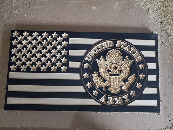
Hey guys. So I’ve been using an old version of Carbide Create for a while now. I finally replaced my old 60 and 90 degree cutters and tried to add them into my old software with no luck, I had to upgrade to V5. So I read some tutorials on how to add new tools on the new software, and have everything updated correctly. Now I’ve completely ruined 2 projects (American flags) and can’t figure out why. The stars on the flag are all rounded, and the crest that was meant to be carved is barely recognizable. Yes, I definitely reset Z with every bit change, and I’ve triple checked my cutting width and flute length. Anybody have any ideas? Is this a common problem with the V5 software? Any help will be greatly appreciated, thanks guys.
one thing that changed somewhere in the late 4 series was that the angle in the tool dialog went from half to “normal” angle… make sure you’re not getting that part mixed up
if you could post an example (even if it just cuts a letter A or something) file it’s easier for us to look though
Thanks for the response. Yes, read that have I do have them set at their full angle. 20201212_181630|375x500
I’ve attached a picture of test cuts of the stars with both bits as I try to work through the problem
One notable thing is Z origin must be set to top for V carving to preview correctly — post the file?
FlagArmy.c2d (1.7 MB)
Here is the file that I’ve been working on.
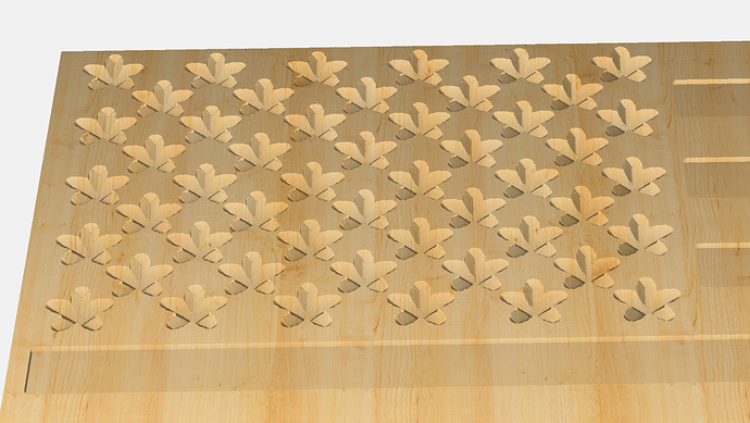
The file setup and 3D preview seem fine:
Please let us know step-by-step how you are securing your stock and setting zero relative to it and a photo showing a failed attempt at cutting still secured on your machine.
As I do for most of my non pass through projects, it is secured with double sided tape. I know that the mounting is not the issue, because this is how I’ve done hundreds of other similar projects with great success. I set zero using the touch probe from carbine 3d. Im pretty confident that this has something to do with the bit settings, but im not seeing where there is an issue
I suspect Z zero set too low. How are you setting it?
If it’s the tool definition, post screen grabs of the tools you are defining.
I am setting zero using the probe from carbide 3d. I’ve checked the depth on the stripes cut with the .125 and they are spot on. So I would think that if it were an issue with setting zero, the end mills would be off as well
As for tools, im using the whiteside 1550 60 degree with 7/16 point length and 1/2 inch cutting diameter. Also the whiteside 1502 90 degree with 1/4 point length with 1/2 inch cutting diameter. I’ve adjusted the file in carbide create to the degree, the half inch cutting diameter, and changed the “flute length” to the point length that I listed.
If things worked well when you Zeroed XYZ, and cut the stripes, that confirms that bitzero is working well.
When you ran second file and Zeroed Z-axis for new V-Bit, is there any chance set the bitzero on the corner, as opposed to on surface, and did a Z-only probe?
Doing that would leave your zero point 3mm lower than expected, and carve 3mm deeper than expected.
Edit: I’ve not had issues adding Vee bits and using them in CC514, everything has worked A-Ok for me.
You could try measuring the furthest out point on a star, and see how deep it is (where the tip of V-bit carved) In theory, that should be almost flush with the surface. It will give you an idea how much you’re out and where to look
I fiddled with your c2d file to see how to create something that matches your physical result.
This is what you get if your v-bit starts 0.1" too low.
Speculation: Since the v-bit is very pointy, perhaps it’s put a small dint in the (presumably older model) bitzero over time… perhaps not 2mm worth, but something that makes v-bits start too deep?
edit: or the vbit is blunt at the tip… or a combination of the bitzero and bluntness.
Wow, that looks exactly like it. Thanks for all of the effort from everybody. I think its time to retire the old touch probe
Before I got the BitSetter the way I would probe pointy endmills was to do it at the far corner from the target — the Carbide 3D Touch Probe as it was then called would actually tilt down rather than get dinged up (and it wasn’t possible to hit the indented circle rather than the surface of the probe w/ a pointy V endmill) — I’d then jog down to just a bit above the BitZero (as it is now called) and repeat the probing so that the endmill was moving more slowly and ought to be more accurately positioned).
This topic was automatically closed 30 days after the last reply. New replies are no longer allowed.


