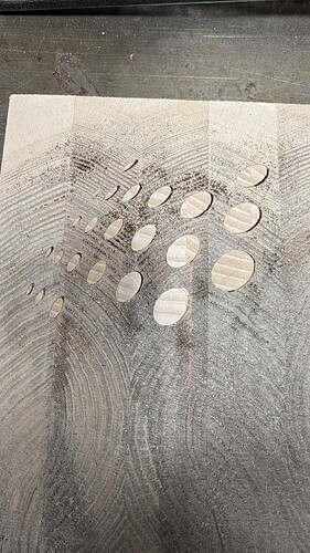
I need help with doing a vcarve inlay on end grain. Using vectric vcarve. I have my pocket depth at 8mm and my plug start depth at 7.5mm and a flat depth of 2mm. (Got those numbers from watching a few YouTube videos) The plug fits but there are gaps around the inlay. Not sure if this is from my toolpaths or if the machine is not cutting appropriately. I have done several epoxy inlays with as many as 9 different colors and never had a problem where I felt like the cut was off but I know that is a different beast the a true inlay. I have attached a picture of the issue. Thanks for any help
Hello David, hopefully I can at least assist you on your inlay journey.
Firstly, it is difficult to tell from your picture whether the gap is all the way around or just in one area, i.e. whether this is a mechanical error or your cut depths etc.
I have made many, some very detailed, inlaid end grain boards with Vectric V-carve Pro. It is great software. Before I went anywhere near trying to cut an end grain inlay board I spent MANY hours practicing with different cutters, start depths, flat depths etc. If you haven’t done this already I would suggest that you go back a few steps and practice. First make both the pocket and plug out of MDF, it is cheap! Write on each piece the tool and depths etc. used, otherwise you will forget and have to repeat. When you have a reasonable fit move on to end grain and see if the fit is as good as you thought.
Everyone seems to have their own way of achieving this aim, for what it’s worth I use a 10 degree tapered ball nose end mill for the first cuts in both the pockets and plug, followed by either (or both) 1/8" & 1/4" end mill to clear.
For the Pocket I use a start depth of 0 and a flat depth of 6mm.
For the first plug cut a start depth of 1.5mm, flat of 2mm, followed by a second cut, start 4mm flat 3 (i.e. a 7mm deep plug to be glued in a 6mm deep pocket.
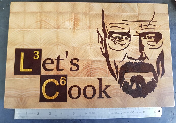
I have found this gives a great fit every time. Below is an example of one of the first, very simple boards I made.
The Vetric inlay has you start the male inlay below the surface. The reason they do that is because if you start the male inlay at the surface the male plug is the same size as the female pocket. That will cause the plug to not fit down into the female pocket. So I would try a prototype an decrease the starting depth of the male inlay and make the male inlay slightly bigger. The only issue I have with making the inlay bigger is it will not fit down inside the female pocket as far and gives you little glue up surfaces where the 2 meet. Plus the Vetric method leaves a larger cavern under the inlay.
Another alternative is to use grain filler to fill the small gaps. You can use water based grain filler and work it in good and hide the gaps. Then you just sand the work piece smooth and remove the excess of the grain filler. You could use some fillers but they tend to be too think and do not penetrate as well as a wetter slurry of grain filler.
I have used this brand with good success. You can get it at Amazon and other retailers. It comes ready to use but you can thin it more with water.

The trick with a grain filler or putty is matching your wood color. That can be tricky.
So you are not using a V bit?
No, As I said, a 10 degree tapered ball nose, with (I’m pretty sure) a 0.5mm point.
Have you tried many practice cuts, or was this your first attempt?
if you use carbide create it has an inlay mode… (I posted a step-by-step tutorial in the tutorials sections some timeago)
now there’s some patterns where the current carbide create does not make the perfect toolpath (a detailed report is filed with support) and one can workaround it pretty easily – but your pattern you have here will not hit that issue.
As part of my investigation into what I thought might be a bug (it was) … I wrote a pile of software to prove that a certain set of toolpaths will be a good inlay for another toolpath… so if you are unsure about your digital side I can run it through that
@Quantock Thank for the reply. This is the second or third try with this same end grain inlay design and none of them worked. I tried just some face grain (much larger) inlays and they looked ok. I tried several different depths but they all still seemed a little loose. It feels like the plug goes all they way to the bottom, I don’t feel like I have to press hard or hammer to get the plug in. I will try some more this weekend. I have done some straight sided inlays on a clock with no problems at all so I dont think (hope) it isn’t a machine issue. Would changing the collet between the clearance path and the v bit path cause problems? The upcut bit I have is 1/4 shank and the tappered ball nose is a 6mm shank. I have not tried to do the v bit pass first and then the clearance.
Changing the collet will not be a problem if you have a bit-setter. If you do not have one I feel it is a “must have item” for inlay work. Life is just so much easier. The beauty of using the tapered ball nose bit is that you can cut some VERY fine cuts, like the whiskers on a tiger I had to cut. The cuts obviously didn’t go fully to the 6mm depth, due to the geometry, but they worked fine.
I have been where you are now, when it all comes together it is worth all the practicing.
Stick with it, and best of luck.
@Quantock I do use the bit-setter for all tool changes. Just wanted to make sure that I understand correctly, you run the v-carve toolpath with the TBN first then run any clearing passes. Also, do you use the bit-zero for setting zero or just use the paper method?
I always set zero in the center of the stock using the paper method.
The reason I always use the center is that despite surfacing, my surface board is not completely flat, I figure that by using the center, any slight zero imperfections are evened out across the workpiece.
Yes, I always cut with the TBN first, as I was doing about an hour ago.
This topic was automatically closed after 30 days. New replies are no longer allowed.

