Unable to create tool path with Carbide Create. I am trying to create a tool path in an Aggravation game board. There are many holes which are 11/16 in diameter. Every time I try it always shows an offset in the simulation even when I tell it not to. I tried every possible combination. No luck. Any suggestions?
Cam8P24.nc (3.5 MB)
Please try sharing your file, maybe we can help?
Possible causes:
- paths for holes aren’t closed — are they magenta? That indicates an open path
- wrong toolpath type assigned, see: https://docs.carbide3d.com/assembly/carbidecreate/video-tutorials/#toolpaths
If that doesn’t help, as @mikep noted, post the file here (or send it in to support@carbide3d.com ) and we’ll do our best to help.
All holes are red after selecting8P24.c2d (127.1 KB)
In that case, it’s most likely a preview issue — there’s an optimization pass to discard small features, which is apparently wrongly happening here.
No, not just a preview issue, I thought that may be the case but I tried it on a test piece of plywood and it drilled as shown in preview.
It looks as if you have a bunch of duplicate circles, and the two which weren’t cut aren’t duplicated and aren’t included in the selection for the toolpath — go in to edit the Toolpath, then control-click on the two errant circles and add them?
I have tried all those things including making all circles from the original one. I was able to create a file with only a few holes, but it seems that C C can not handle a large number of holes.
Maybe I am doing something wrong. I wonder if someone could try to write such a file. I need to find out if I need to use another application.
I have tried small test files with some positive results, but only for about 20 holes or so.
Thanks to all who have helped!
Okay. When I run up against situations like this, my solution has always been to divide and conquer — assign toolpaths to half the circles, then repeat with a second set of toolpaths for the other half — repeat this division until you arrive at a low enough quantity that things work.
Hopefully a developer, @robgrz or @edwardrford will chime in on this.
Thanks, sure will give it a hell of a try!
I believe that the culprit was my bit. Changed to a ball and it worked.
2 Likes
Was the ball end mill same size as the square endmill? Curious , cause changing from the cutter type, square to ball shouldn’t have mattered?
If you hole isnt large enough for the cutter it won’t show a tool path. But it will let you create it.
Just won’t see anything on the preview or the cuttter trace won’t show either.
I always make a circle the same size as my proposed bit and run it around my design to make sure it will be able to fit where I need it.
1 Like
Still having big problems. I am trying to use a 3/4 inch core box cutter on a 3/4 inch circle (hole). I am not able to get a tool path to show. It keeps telling me an offset of 0.337. I do not think it is needed. I tried removing it and set the offset to 0.00 and it made no difference. After the tool edit, the offset shows up again. I am about ready to take the whole thing to the dump!!!
Sure appreciate your help.
Please post your tool definition / description — there may be something in that to correct/adjust.
Does the CAM setup work properly with default endmills?
If the holes are ~10% larger in diameter than the diameter of your endmill it ought to work — post the file here or send it in to support@carbide3d.com along w/ the endmill definition (I guess a screengrab) and we’ll see what we can puzzle out.
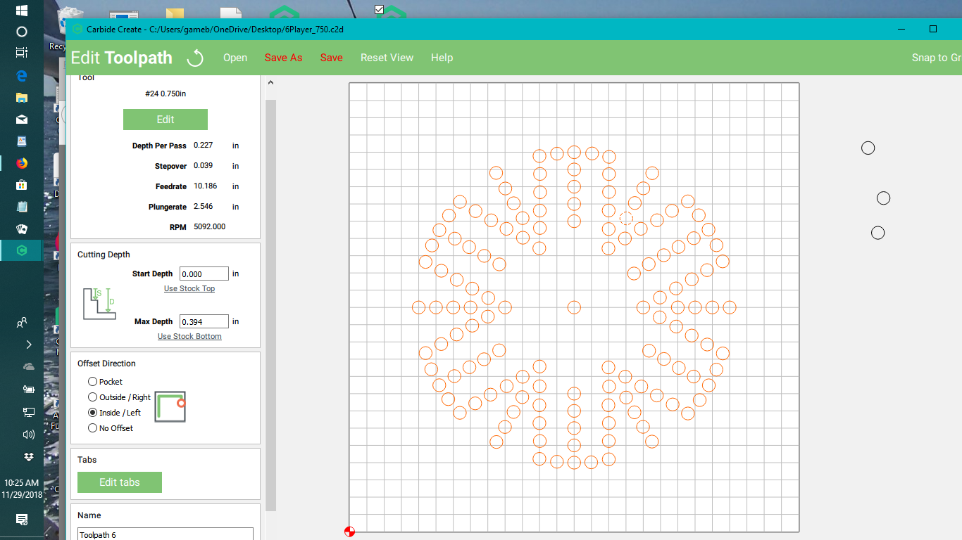
6Player_750.c2d (96.1 KB)
The holes are 0.75inches in diameter and you’re trying to fit an 0.75 in endmill into them — the geometry has to be at least 10% larger in all dimensions than the tool — increase the hold diameter to 0.825 and it works.
2 Likes
That hole is way too large. 3/4 inch is as large as I can use. So I need a smaller bit? I don’t see why I can’t drill a 3/4 hole with a 3/4 inch bit.
I bought this XXL machine for this purpose and it looks like I really wasted my money!