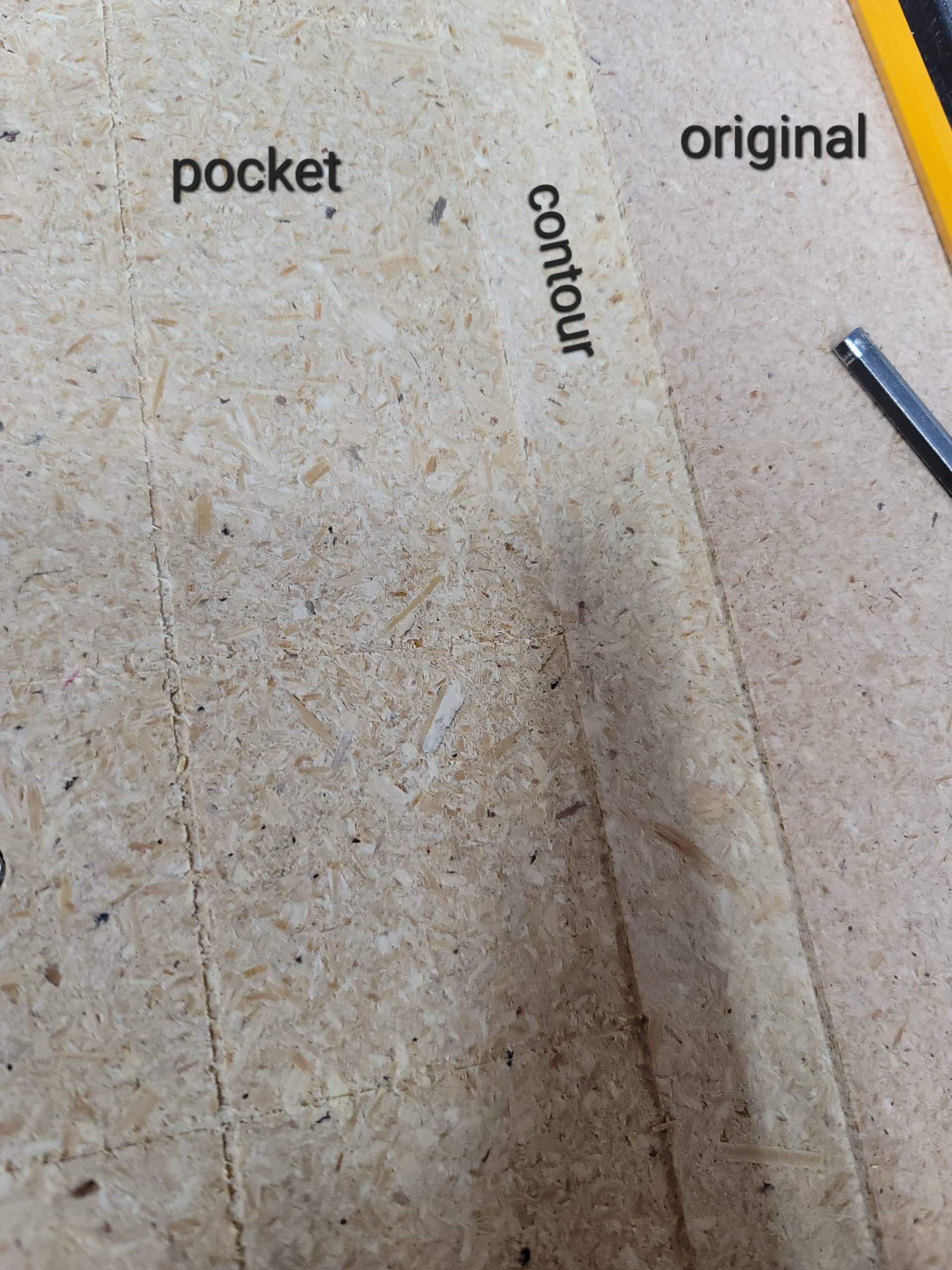
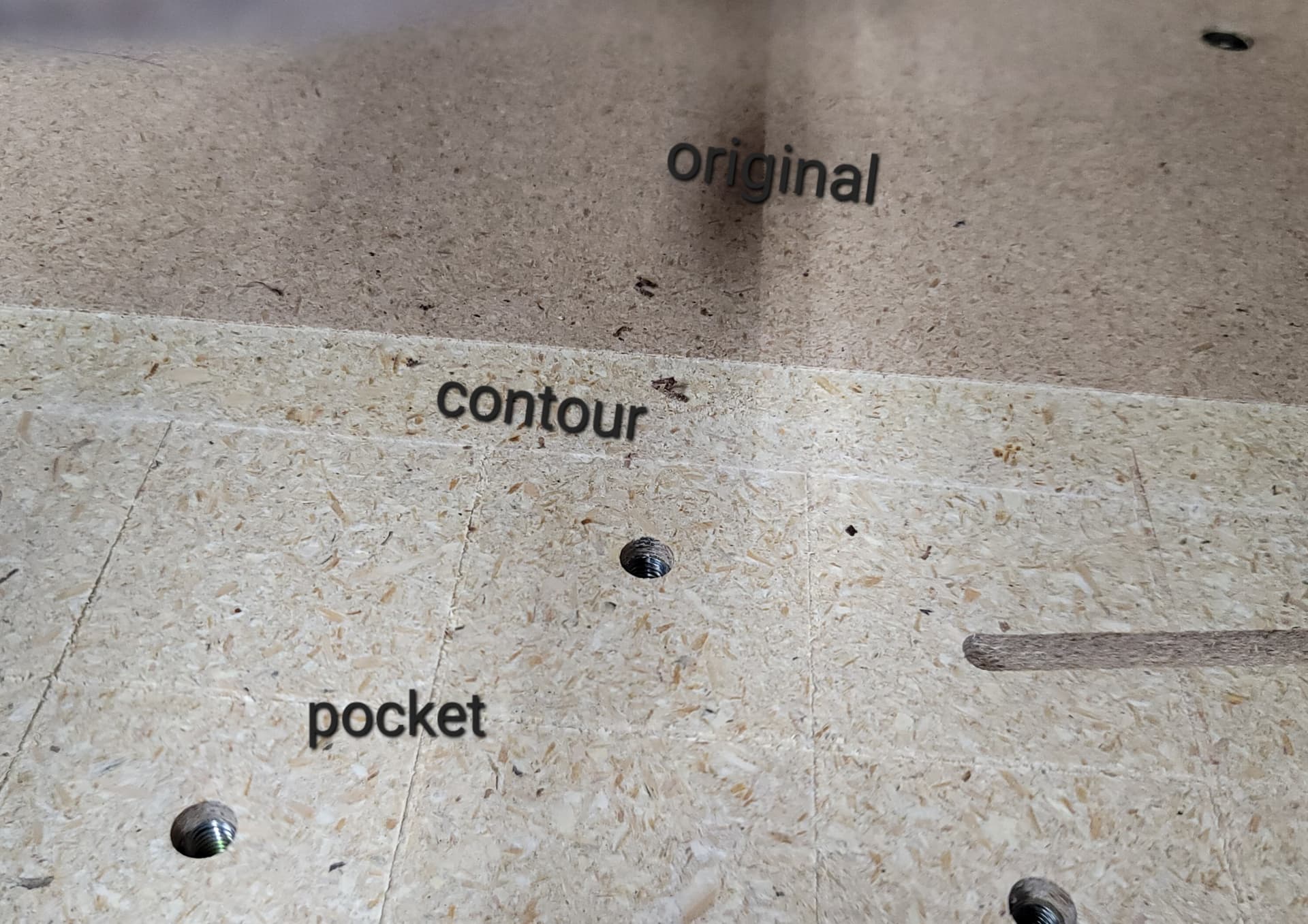
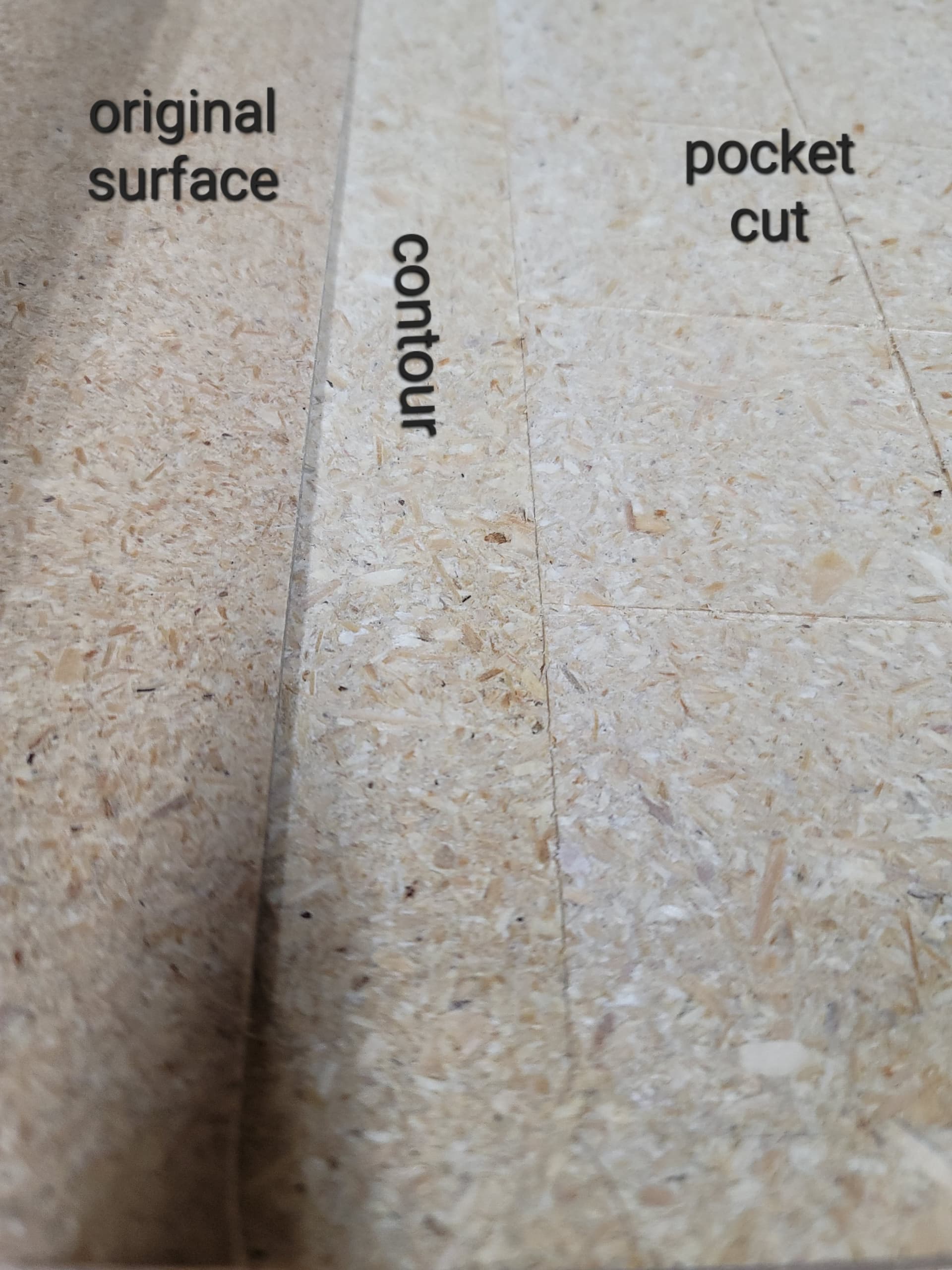
Using a Shapeoko 4 with an mdf work surface that I’ve made. The mdf work surface is bolted to the machine in place of the original mdf strips it comes with. Ive quit using vee bits because words rarely come out evenly cut, height wise. I decided to resurface my work table using a 1" surfacing bit. I made a gcode to pocket a 31" x 15" square at .0625" depth. After running that, I immediately decided to go ahead and increase the resurfaced area to the max by making a gcode to contour the outer area of the square at .0625". I left zero as is. I didnt even jog it any. The contour came out being slightly lower than the pocket cut area on one side and slightly higher than the pocket cut area on the other side. Any ideas why this might happen?
Have you trammed your MDF?
What is the depth per pass and the total depth of cut for each feature?
Post the file and a marked up photo which shows the various depths?
I’m not sure what it means to tram the mdf? Its been my work surface for about 2 years. I set the max depth at .0625" for both runs and i also set that as the depth of cut for the bit. I figure even if something isnt squaredBy depth of cut I meant depth per pass the two cuts should still be level to each other since nothing was changed or moved in between the runs. What does it mean to tram? Google isnt making it make sense for me.
Im not sure which software you use but i get that with f360 which insists on including “stock to leave” at 0.5mm for pocket paths. Maybe check your CAM settings?
2 Likes
Tramming is a process to ensure that your spindle/router is perfectly perpendicular to the spoilboard. You may need to adjust the spindle left/right or front/back.
Typically the process is to slightly surface the board, tram and then resurface the board. At that point the board should be flat relative to the spindle.
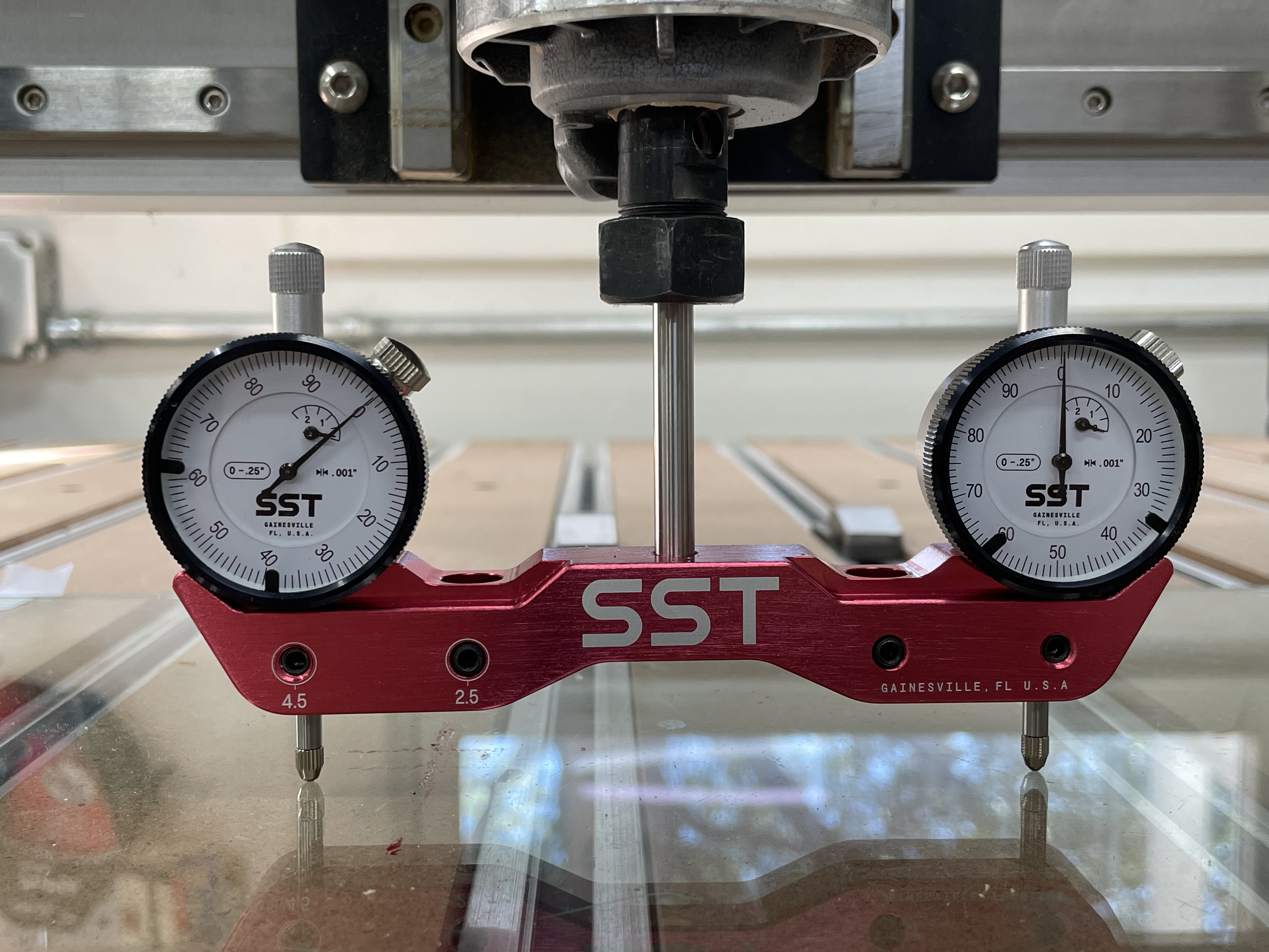
It was a pain the first time I did it but once you understand the concepts it’s not so bad. There are lots of posts on here about the methods in detail, just search for tram. Some people use home made devices to assist in that process. I tried that but wasn’t happy with the results so I bought the SST Mini tramming gauge and a piece of glass that purports to be super flat. I am happy with the results I got.
The type of work you are doing will dictate to some degree how critical it is. If you are making large signs then the impact is likely negligible but if you are doing more intricate work and very small V carve lettering it is more important.
EDIT: here is the setup I used, but like I say others on the forum have created their own devices which probably get you good enough without worrying about tiny decimal places.
4 Likes
Even without doing the tramming process, if the router is not perfectly perpendicular, wouldnt the 2 cuts still come out evenly compared to each other?
Hard to really tell from your picture but I am assuming you are comparing the original surface to the left edge of the cut on one side and to the right edge of the cut on the other side.
So, if the router is not perpendicular to the board then the bit will be slightly tilted. That tilt is exaggerated more with a larger bit.
1 Like
There are some very good images in this thread showing the geometry of tram error. There are two axes of tram to worry about and the error shows in a motion perpendicular to the error. Error left to right (Tilt) that will show up most on cuts front to back. Error front to back (Nod) that will show most on side to side cuts.
1 Like
This topic was automatically closed after 30 days. New replies are no longer allowed.