Can you just please explicitly confirm that you do see those “Sending Config: 34 left” messages when clicking on “Send Config Data” ?
Allright, well we need to get to the bottom of this because I’m pretty sure that the config params somehow do not get sent to your controller.
For example, your machine has $3=6, which means “invert X and Z direction”, while the Shapeoko config that CM sends sets $3=2 (which means “invert Y direction”). I just verified that if I alter $3 to some random value, then click “Send Config Data”, after the update the $3 is back to value 2, so CM definitely sets that.
Can you please type $I in the MDI command line and grab the output from the log window ? I would like to double-check that your upgrade to GRBL 1.1 was actually successful. On my machine, I get this:
$3 is set to 6 — since this predates the HDZ, it should be the correct setting for a machine which doesn’t have an HDZ, and on which the HDZ checkbox is unchecked.
Allright, so we have established that GRBL 1.1 is correctly installed, and all $ params are OK.
Let’s go back to the original issues you reported:
Issue1: rapid positions that behave kind of like you had an XL, not a SO3. Wild guess: since rapid position coordinates are dependent on the machine size AND that this information (coming from the dropdown list in CM) is not stored in the controller but somewhere locally on the Mac, could it be possible that an earlier setting from previous installs is being used ? I wonder if it would be worthwhile to try uninstalling and re-installing Carbide Motion completely, repeat the configuration procedure, and see if that solves anything ?
EDIT: or the even better version of that test: trying with a different laptop/PC/Mac…where CM was never installed earlier.
Issue 2: Zeroing Z using the probe with a V-bit: that should work fine. Can you elaborate on what you did and what you saw when doing that ? Test procedure: lay the probe on top of the stock (WITHOUT overhanging the lip), do the probing cycle for Z only, remove prove, manually jog (carefully) until you reach the stock surface: what value does Z read then ?
Issue 3: could you share the design file (CC?) and g-code file you ran when you had this 1/2" depth of cut versus an expected 0.09"? The most “typical” reason for cutting/diving too deep is crashing the top of the Z upon retract, due to retract setting + router position in the mount + thickness of the stock.
Julien,
Issue 1. Great Idea. I had 2 previous version on the machine.
Deleted ALL versions of CM.
Restarted the MAC… just in case anything was hanging around in memory.
Loaded latest version of CM.
Followed These Steps.
Powered on CNC
Started CM… [Connect to Cutter]… [Initialize Machine]
[Setup Shapeoko]… select Shapeoko XL… then select Shapeoko.
[Update Shapeoko Configuration]
[Send Configuration]… watch countdown.
[Run]… [Initialize Machine again].
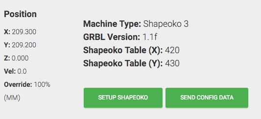
Here is what I think the issue is. I hope this screen shot uploaded.
The X and Y are showing the max position I can jog to. The Table (X) and Table (Y) are nearly 2xs that.
I’ll worry about Issue 2 and 3 when this ‘doubling’ problem is resolved. I’m half convinced they are all related.
Now when the probe descends on pad, the light turns red but the Machine does not back off. It continues to try and drive the bit lower. It’s not pretty.
Yes… the toggle switches addressed problem number 1. Mostly. Selecting the left-front corner still causes the limit switches to be hit. I may return to this later or live with it.
Thanks so much for your help. It was very much appreciated.
Just out of curiosity, you mean you have limit switches on the left and front side of your machine ? Are you homing there or in the back right corner ? I don’t know the design of early Shapeoko3s, so any detail that makes them different from current machines (e.g. those DIP switches) is interesting to know about to solve your problems.
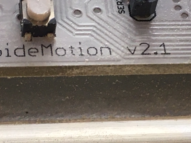
I believe I have it set up per the instructions. Photos Attached.
I had my doubts that I had established a good ground so I tapped the cover and now ground directly to the motherboard cover.
Here is the behaviour that I’m now seeing consistantly.
CNC On… Test probe… green to red
CM On… Test probe… green to red
CM… Connect to Cutter… Test probe… solid green… never recovers.
Another guy had a very similar problem. Not sure if it’s resolved.
Can you try grounding the alligator clip directly to your board?
In your picture showing the connections, the pin you hooked the red wire to is +5V. Two pins to the left (as seen in your photo) is a ground pin.