I haven’t been super fond of the stock spindle driver that comes with the Nomad (McGillicutty).
- It doesn’t seem to actually output the rated 300W.
- The driver, Allegro’s A4962, uses trapezoidal drive.
- The FETs are not that high quality. The PMOS used has quite large Rds(on), 65mΩ. Both NMOS and PMOS are quite slow, the former has a rated fall time of 100 ns. They also both have higher gate charges than I would like. They are just not the kind of FET I would like to see in a motor driver.
- The sense resistor is not using a kelvin connection
 .
. - It’s fragile, with very little in the way of fault protection. We’ve got two fat TVS diodes, and that’s it. Stalling the motor seems to fry the board instantly a majority of the time.
- IMO someone went a tad overboard on the number of caps.
- It isn’t open, nor is it extensible.
I figured it would be fun to try and design an upgraded driver that I could use in its place. With that in mind, meet the v0.1 (I’m not good with names) McSpindle Driver!
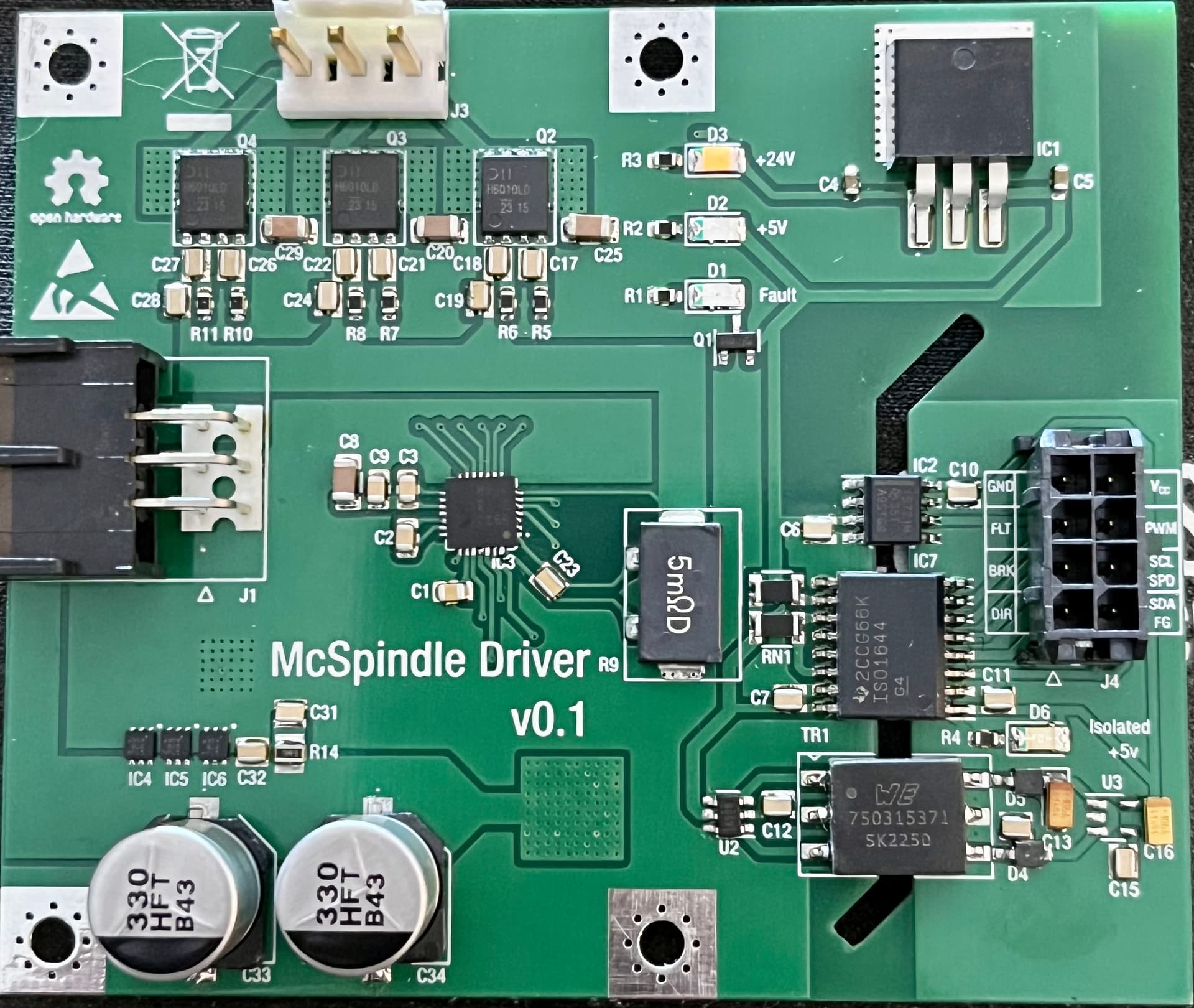
This is my first attempt at creating a replacement driver board so I’m expecting it to not work/have some number of problems.
I decided to stick with Allegro for the actual driver chip and went with their A89307 as it seemed ![]() fancy
fancy ![]() and I like fancy. The main highlights here are:
and I like fancy. The main highlights here are:
- Vector control

- 4 pin sense resistor w/kelvin connection.
- 3 phase inverter made up of three dual n-channel FETs (MTH6010LPD). These things are super great. They’ve got:
- Typical Rds(on) of 8.5mΩ.
- Low Miller charge.
- Exceedingly fast – 8.8ns rise time and 7.4ns fall time, 34.5ns for the body diode recovery time.
- Fully isolated control with isolated power. The control circuitry is not on-board, primarily because this is the first iteration and I wanted to focus on the driver. What is on-board however is:
- +5V, 150mA isolated power supply via mini transformer with push-pull drive.
- Isolated PWM signal from the Carbide Motion board.
- Isolated I2C+control interface for the A89307.
The A89307 has quite a lot of configuration that needs set, which is what I am working out now. The documentation is a bit lackluster so there’s a good amount of experimenting here.
So far the biggest unknown for me are the motor constants as the driver needs Kt to be set . The best guess I could come up with for these are
Kv = 24000rpm/24V = 1000rpm/V = 104.7 rad/V·s
Kt = 1/Kv = **0.00955 N·m/A**
Now, what are the units for the Kt register? I have no clue. The register is 9 bits wide so we have a range of 0-511. What I’m going with for now is that it wants N·m/mA which would in this case be 10. ![]()
Similarly (noticing a trend here) there are no explanations for what units the inductance register should be in. I’m going to assume it wants µH which I measured as 300µH phase-to-phase. The register is 8 bits so we’re going to need to use the inductance_shift register. Setting that to 1 lets us use 150 for the inductance register.
Will post the full configuration later on when testing and I plan on continuing to document this as I go!