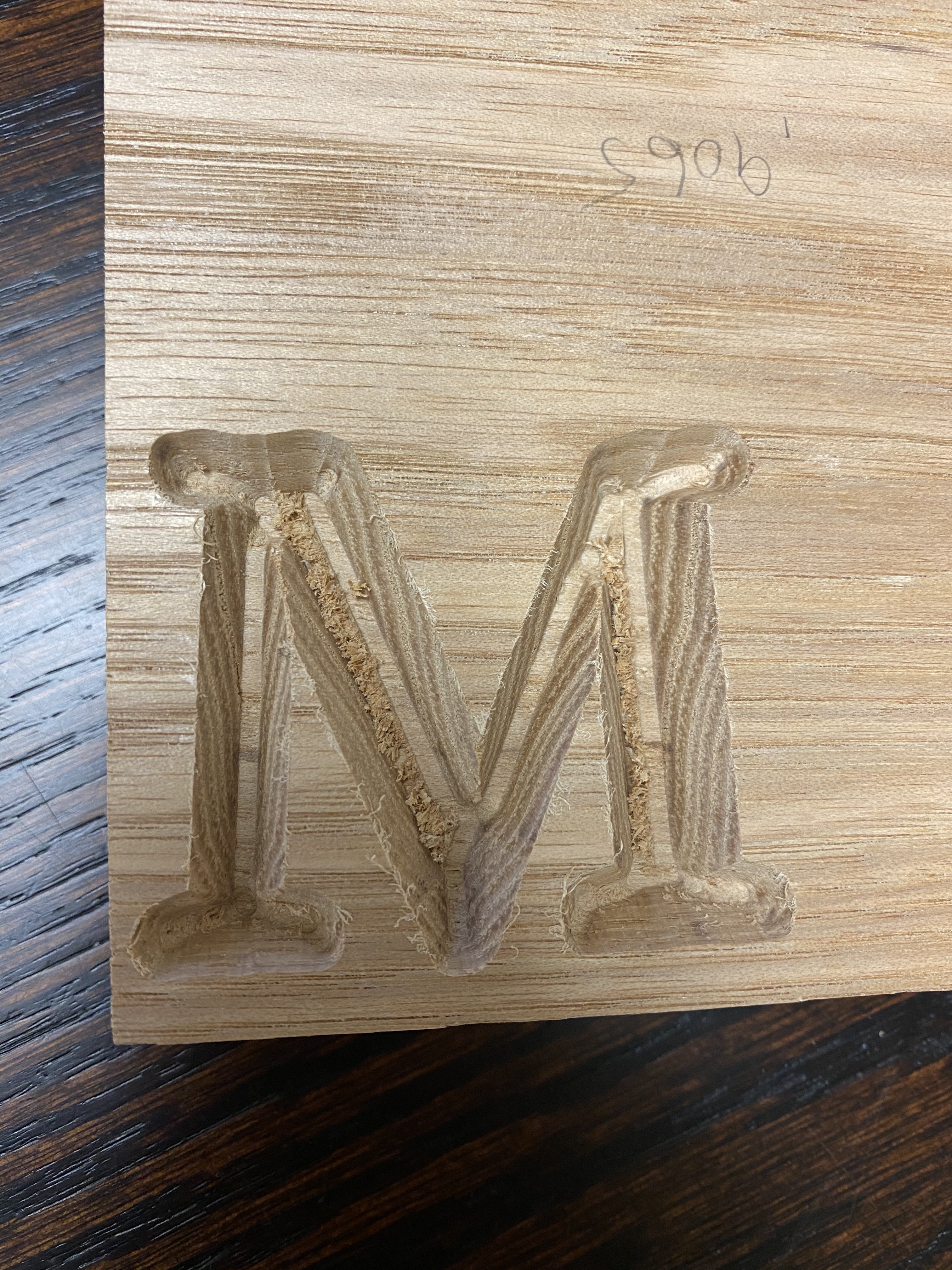
So I tried this last night and had some really interesting results. Up to this point I haven’t had any issues cutting anything. But when I was doing the Advanced V Carve steps 1-5, the resulting cutout looks terrible. I’m losing all of my detail which is the whole point of doing a V Inlay. I tried two different 60 Degree V Bits, I re-Zero’d the machine with the touch probe three different times and each time yielded the same results? Any thoughts? I copied your settings exactly except for my stock thickness. I input my own value there for my material thickness as checked with calipers.
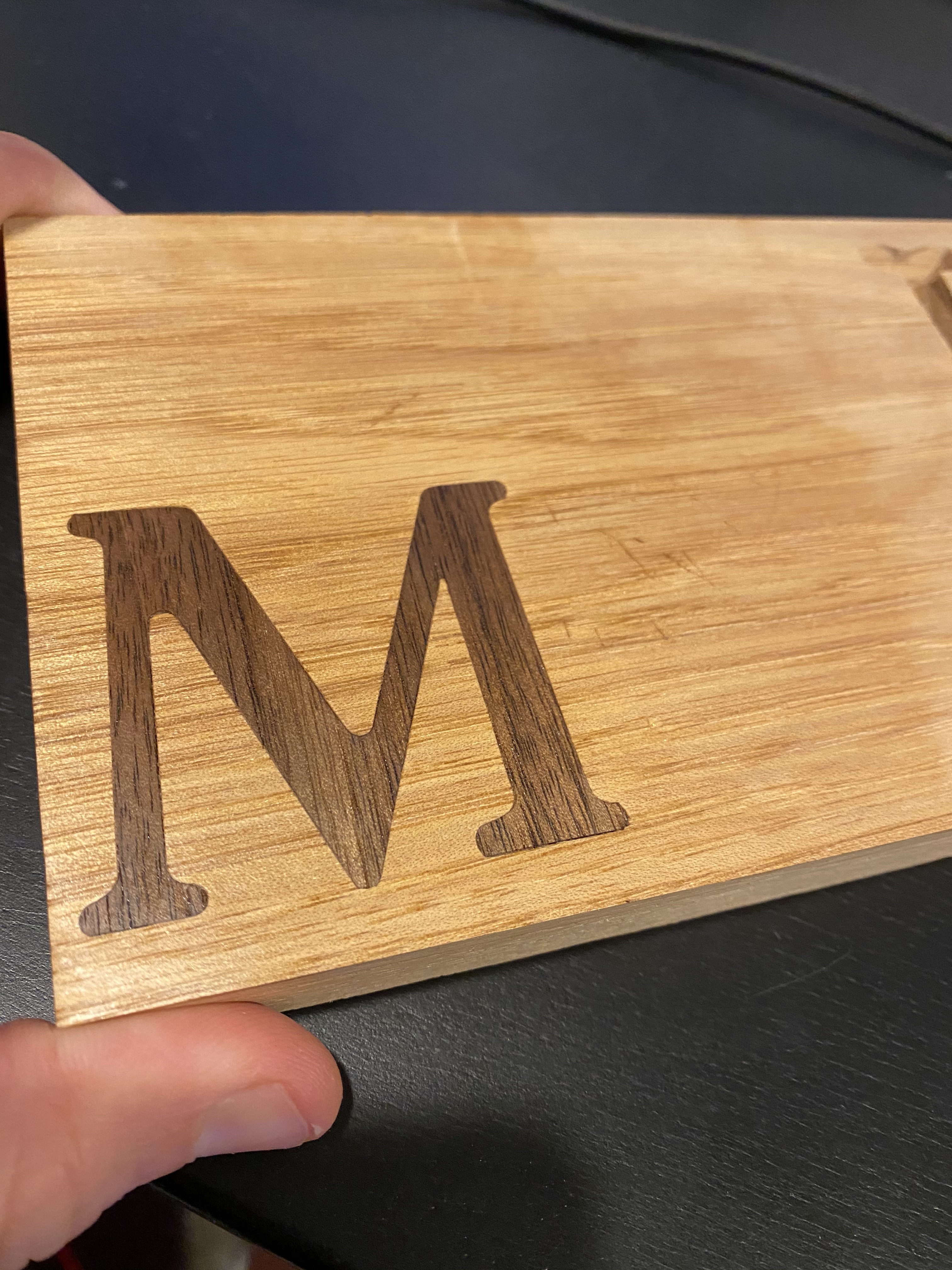
In addition, after not being able to find the issue here, I did an inlay using a straight 1/8" pocket cut for the mortise and a outline cut with an 1/8" bit for the plug, then I hand chiseled them to fit. It worked great. But I still want to figure out why my V Bit cut looks so bad.
I have been thinking about this approach, and I have an idea that I will try, but I want to run it by you all quickly.
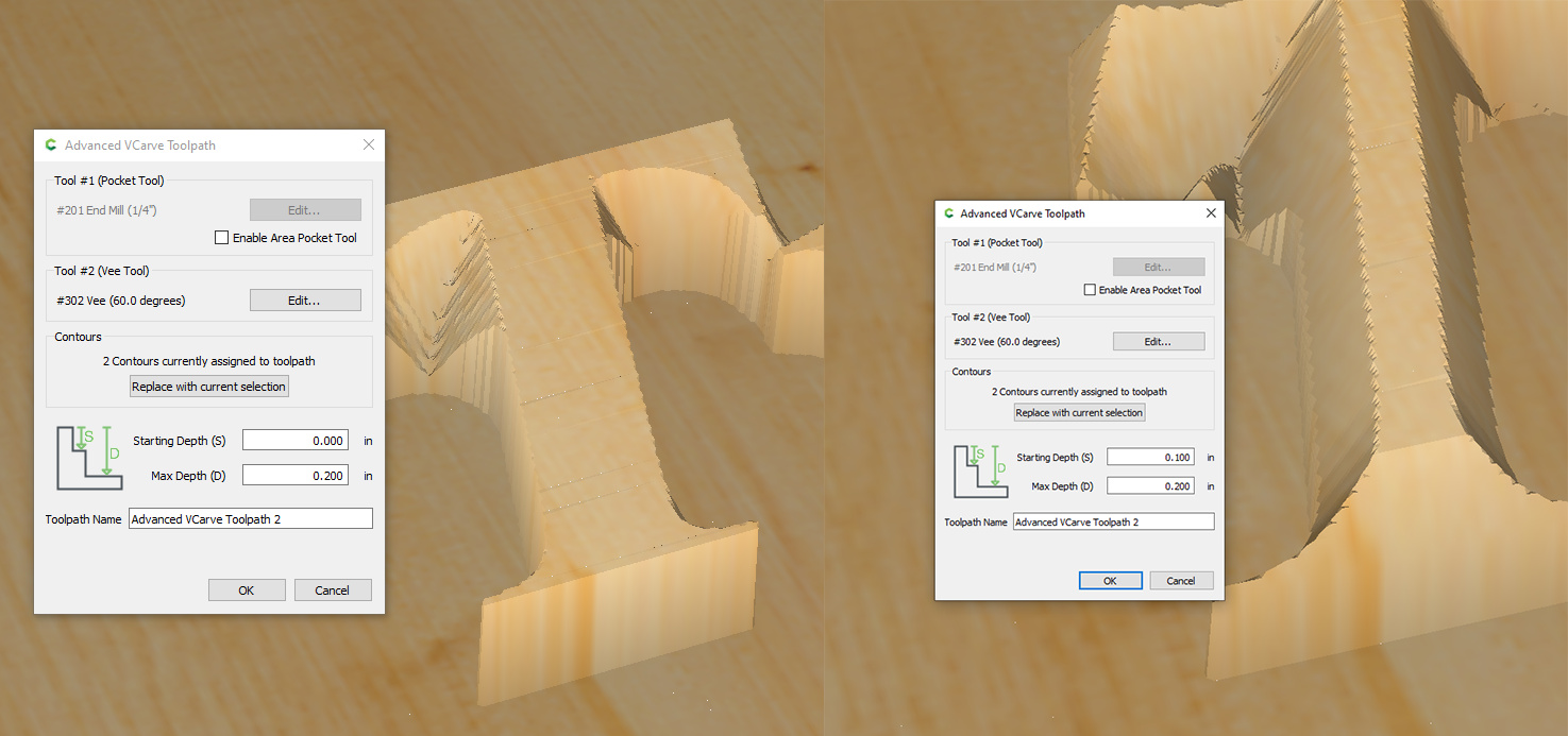
Rather than adjusting the “male” end of the inlay by changing the Z height, could we get the same result by adjusting down the starting height of the V carve? Check out the difference when I lower the starting depth by 0.1:
@iantyndall I have not tried a v inlay with the new versions of CC, but I’ve used the old versions and just about every other software out there. The two methods you’re describing are essentially the same thing. The only thing that would make the method different (and better) is if the toolpath generation still tasted that first .100" as stock to be removed instead of ignoring it. Basically, if you set your DOC to .100", does it actually start at .002", ignoring the first .001" of Start Depth?
Instead of manual changing the Z why wouldn’t you just find the Z and then adjust it up the .1” or 2.54mm and set that as your Z?
I have been playing with inlays for about a week and it has been coming increasingly frustrating as I am having this exact problem and things aren’t fitting just right! I am planning on giving your suggestions a try tomorrow and hoping for good results! Thanks for the tips!
You would need to adjust the z down, not up. The idea is that the new Z should be below the surface of your work and that adjusting it using the field would be quicker. But you Could adjust it outside the boundary of your work piece and it should work just fine.
adjusting the outside boundary mostly works, but it does not work for all geometries.
A v-carve is “sharp” and matching exactly on 1 horizontal plane, the plane where the design intersects the bit. The trick is to have these planes of intersection be the visible part of the final art work, which is what the Z shenanigans is doing
I wasn’t saying to adjust the outside boundary of the design, I meant to re zero the bit outside of the boundary of the material so you could actually set the bit deeper than the surface of the material without possibly driving the bit into it.
@iantyndall. I think your approach works. I’ve not tested with an actual cut, but I’ve tested in CC and I get the same results. It cuts the profile at the depth of the starting depth setting. The nice thing about this approach is you don’t actually have to stop and change the Z height allowing you to use one toolpath. One other point that the illustrations don’t clarify above is that setting the Z zero lower will move the bit down into the material more. In the examples above, if you were really working with material of that thickness, the adjustment of the Z zero might put the bit all the way through the material. Just something to be mindful of if you’re using the manual Z approach. If using the “Start Depth” method, you can also set the “Max Depth” giving you more control of how deep the bit goes.
Doh I meant adjusting it down. That makes sense having to do it outside the workspace. I use the touch probe so once I had my z point I figured adjusting it down would be a snap.
I am still learning the advanced v-carve feature but isnt adjusting the Z starting depth done in the advanced v-carve toolpath? There is an box for it.
So if we use that we can skip step 12 and lowering the Z? I am still having issues with the plug just barely fitting. If I am using thicker stock and want to fit more into the I change the Max depth deeper and adjust the starting depth on the plug but still get very little penetration and end up with the huge glue zone and hollow space. How do I get more of the plug deeper.
This is probably super easy and it is just not clicking in my head. If I adjust the starting Z point lower on the plug shouldn’t I be fitting more of the plug into the hole?
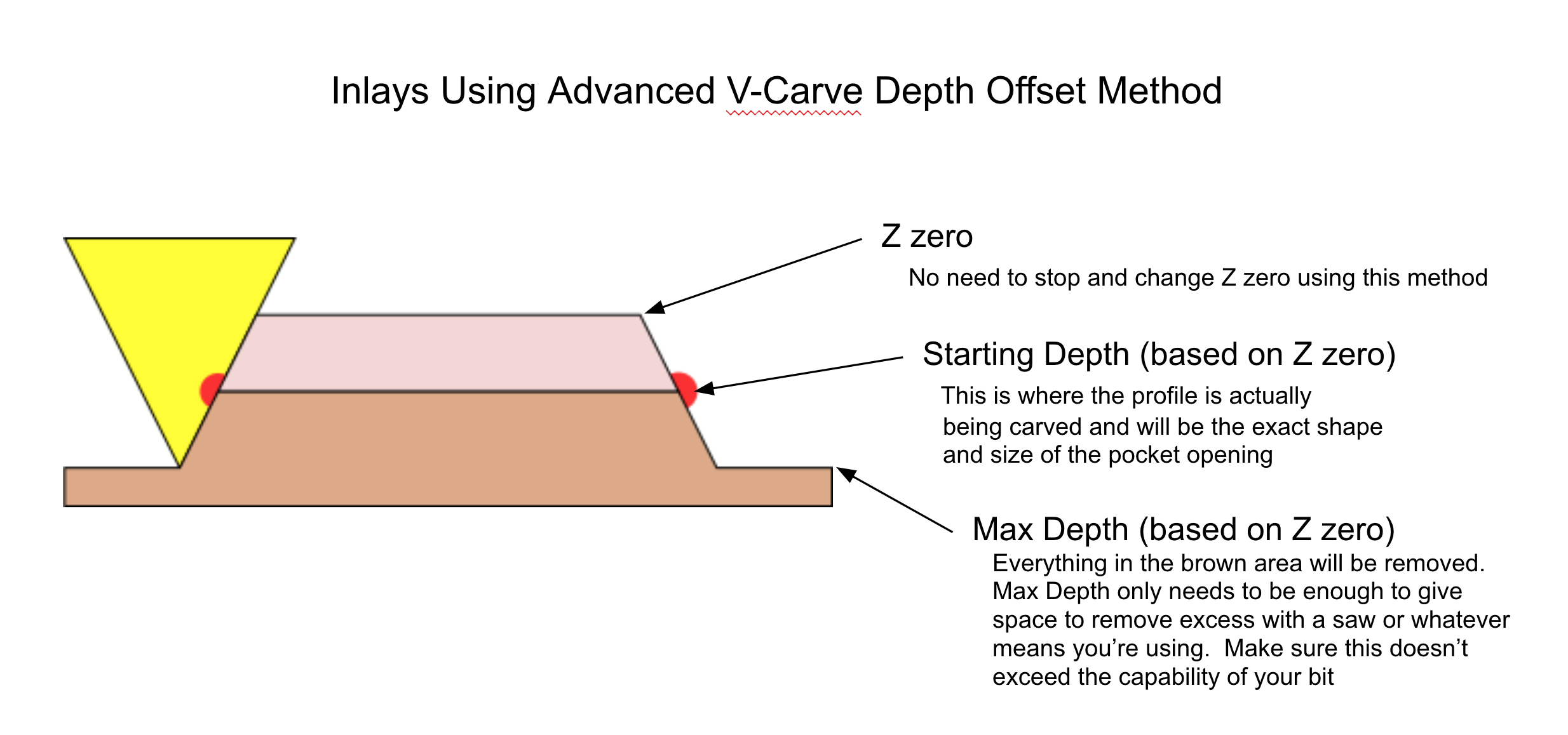
You should be setting the Start Depth to the depth of the pocket minus whatever space you want for glue. For example. If your pocket was .25" deep. I would set the Start Depth to .20" which would leave .05" for glue. That might be too much, but this is an example. Then, the Max Depth setting determines the amount that the plug sticks out of the pocket. I would probably add .05" to .1" just to give space for a blade or something. So overall, for a .25" pocket, I would set Start Depth to .2" and Max Depth to .3". One more thing. Max Depth is not in addition to the Start Depth. It is from Z zero.
I ran a test of both methods. I have to say that I am not very good at the Z height adjustment method because I get inconsistent results because of my short working memory. Or lack of attention to details…
Anyhow, for my test I cut a female pocket of 0.2.
For my male insert I wanted to cut it to 0.1 with the remainder for glue (I know this is a lot, but I am still very new to this and wanted to err on the side of the piece fitting).
I don’t think I did the Z height adjustment correctly. The piece didn’t fit.
My order of operations was to
1 Cut the pocket for the entire piece
2 Cut the inlay with vee crave starting depth of 0.1 and a max depth of 0.2
3 Stop the process. Go to Z10 and reset to Z=12.54
Run the vee carve on the second line