Given an effort to make the parts for:
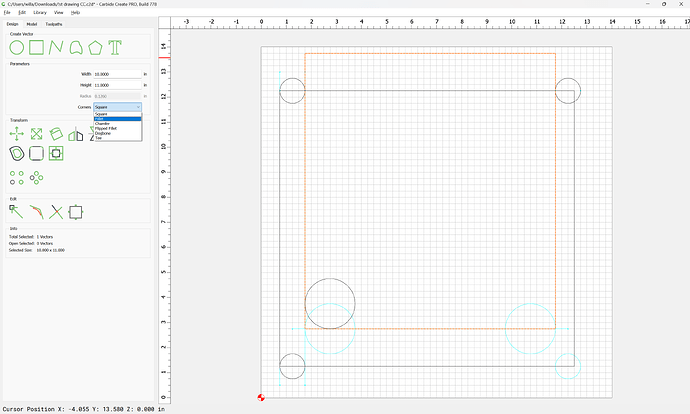
We start with a file:
which at least provides some rough dimensions and so forth.
Presumably we want:
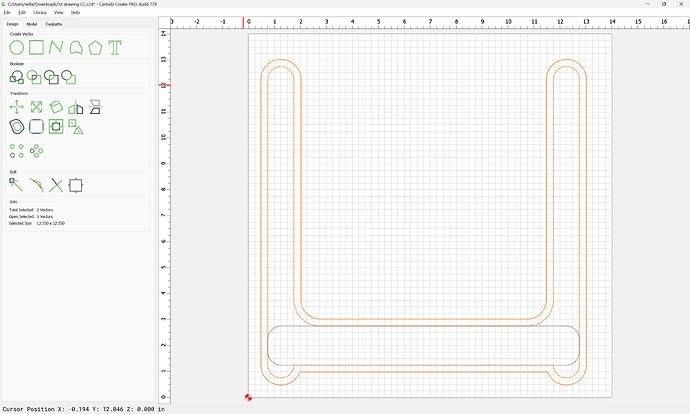
- an island at the front bottom (this will set the spacing when the pieces aree bolted together)
- a series of fingers which rise up on either side (to guide the knife)
- some holes for threaded rod or a dowel to hold things together
We start by sending everything to a background layer for reference and locking that:
For the specifics of using Layers see:
Then we draw in all the geometry needed for the design:
Note that for Trim Vectors to work it will be necessary for elements to cross in such a way that the intersection can be detected by the tool — such a design may be drawn in multiple ways — try different arrangements as seems fitting.
e.g.,
(but note when selecting for the Trim Vectors operation one does not want overlapping segments which can confuse the algorithm)
Presumably the large circles are wanted to round the interior:
An easier way to do this would be to round the rectangle which makes up that section:
With all the geometry drawn (and corrected/adjusted if need be), select it all:
and use the Trim Vectors tool:
to remove what is not wanted:
If there are segments which cannot be removed, click “OK”:
and draw in a temporary line or other object which defines where the cut should be made:
Done
and try again:
If things still don’t work, try Node Editing:
right-click along an area which one wishes to remove:
and choose “Cut Vector”
Done
Delete any cut segment:
reselect:
and do Node Edit again:
Select the two nodes which are at the ends of the segments which you wish to remove:
and press d to delete:
Repeat for the other end (or copy-paste):
Select all of the open/trimmed geometry:
and use “Join Vectors” to close:
Yes
Draw in the base for the bread to rest on:
and round the corners:
Then select the original geometry and offset to the outside by tool diameter plus 10%:
Apply
Select the offset geometry and the base:
and assign a Pocket toolpath to the desired thickness of the knife slot:
Then select the outer geometry and the outline:
and assign a pocket starting at the bottom of the previous one and going down to the tab height:
Then select the outline:
and add Tabs:
OK
and assign an Outside Contour toolpath which starts at the bottom of the previous pocket:
Lastly, draw in geometry for the holes for the rod/dowel (we will assume 8mm (5/16")):
(we will allow an extra ~10% for ease of fit)
and machine a pocket to cut that all the way through as the first operation:
and verify the simulation:


