A while back I did a thread on this in the Lounge ( https://community.carbide3d.com/t/using-abusing-multi-layer-v-carves-for-joinery/19711 ) — since then, the V carving features in Carbide Create have gotten much more flexible, so it’s a bit more straight-forward to use (abuse?) them for this, esp. if one uses two 90 degree V endmills, one large enough to cut all the way through the board leaving a 45 degree angle at the end, the other suitably smaller (exactly how much smaller it must be will be worked out in the course of drawing this up and modeling it).
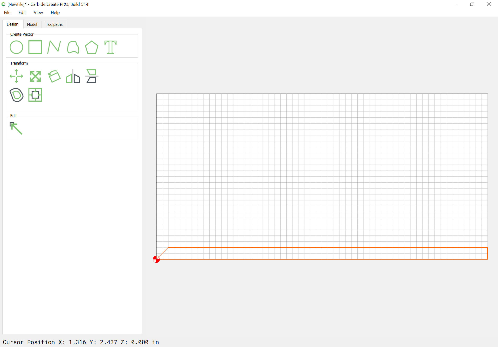
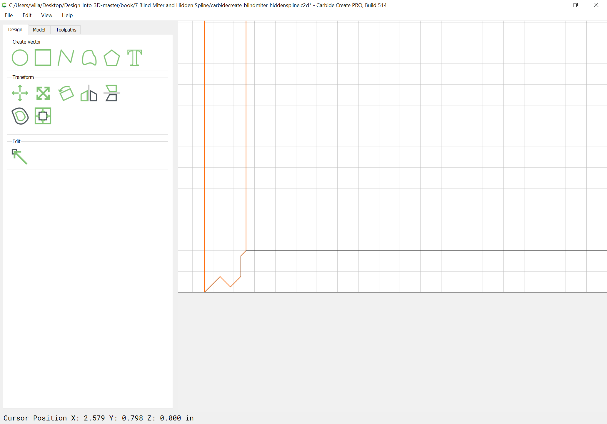
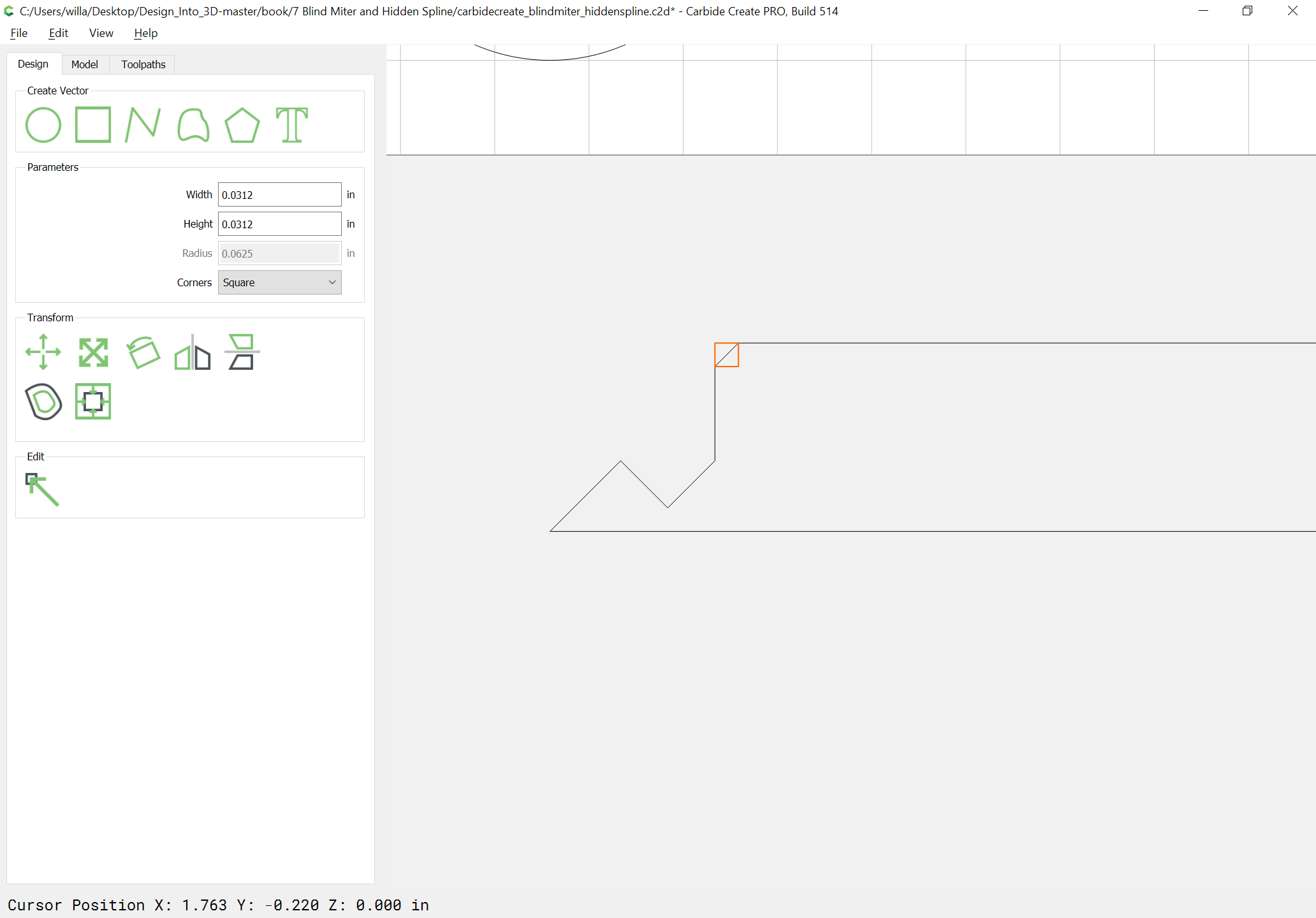
The problem of course is cutting a pocket for a spline (and later a spline) without requiring re-orienting the board, or some specialty tooling. Drawing in the profile of a smaller endmill suggests a solution:
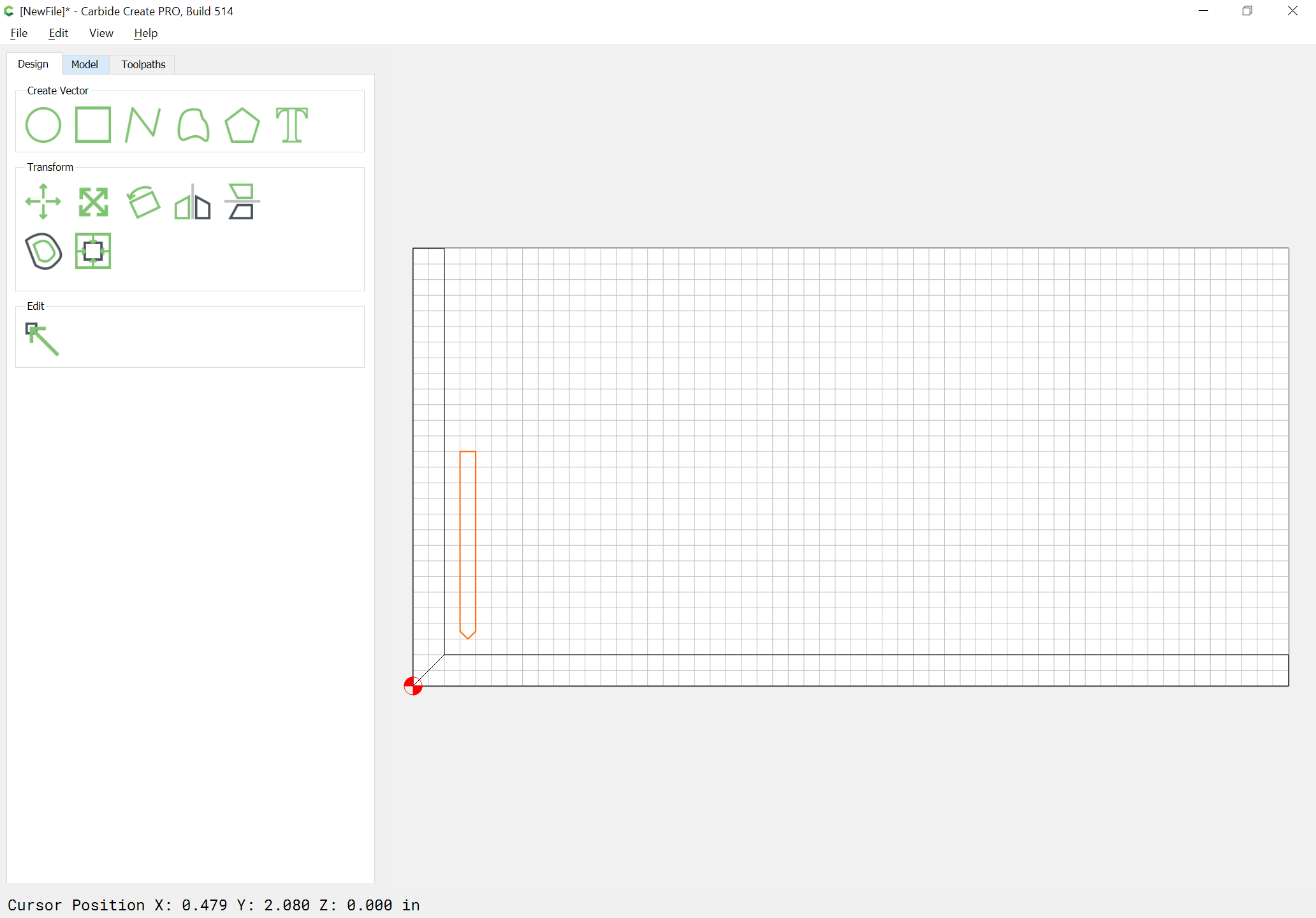
which is a reasonable thing to cut and isn’t too wasteful of material (alternately, one could cut the splines from suitably sized stock, or more likely in a different orientation — for the nonce this orientation will be used since it makes the relationship of the parts more clear).
Making that spline is going to be tricky for a tight fit. Just like any spline, it will have to be undersized, but by how much? That is the real question.
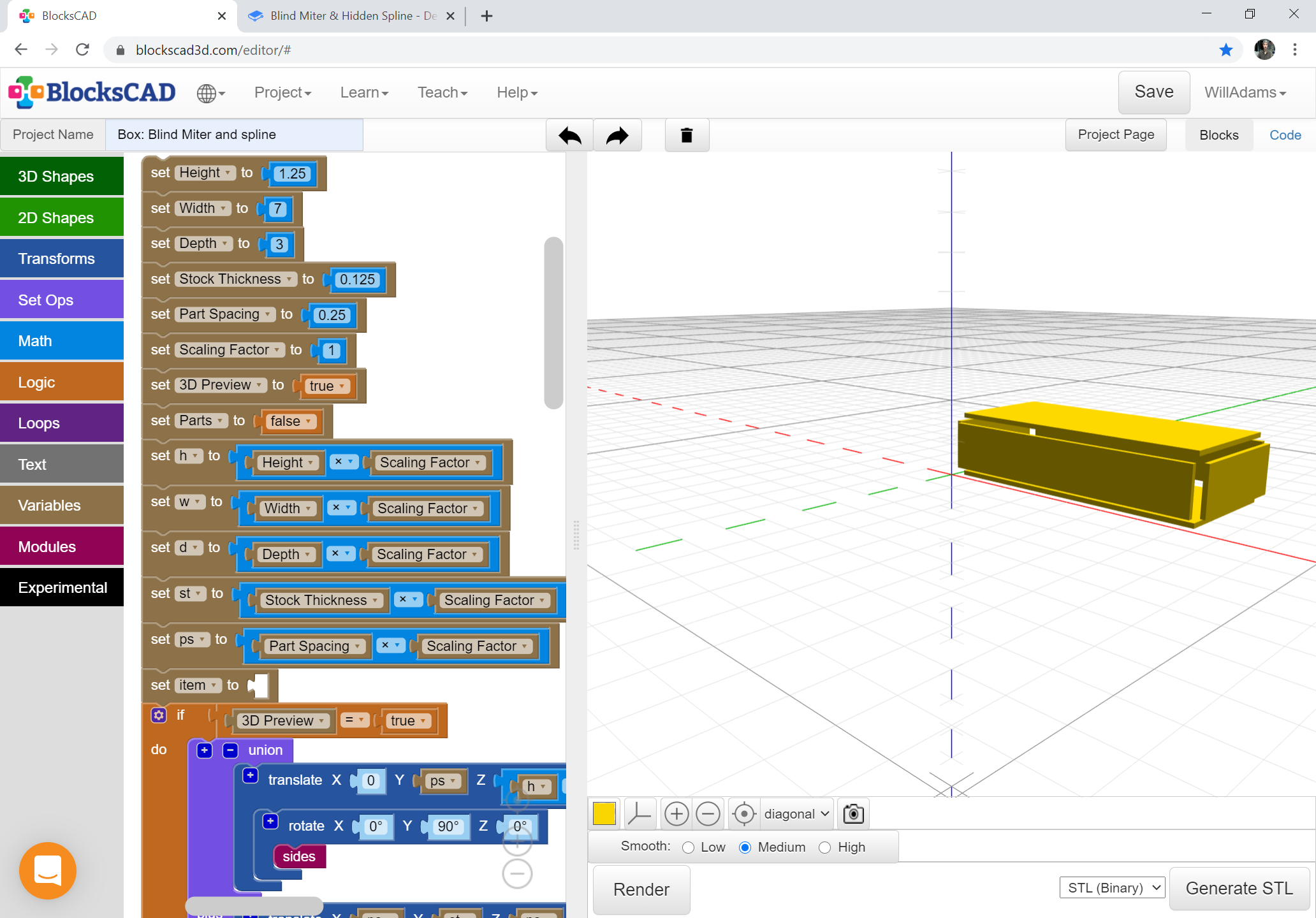
That’s one of the advantages of (ultimately) doing this programmatically/parametrically — I’ll be including a parameter, “Glue Thickness” which will allow adjusting for that and fit in 3 dimensions all at once.
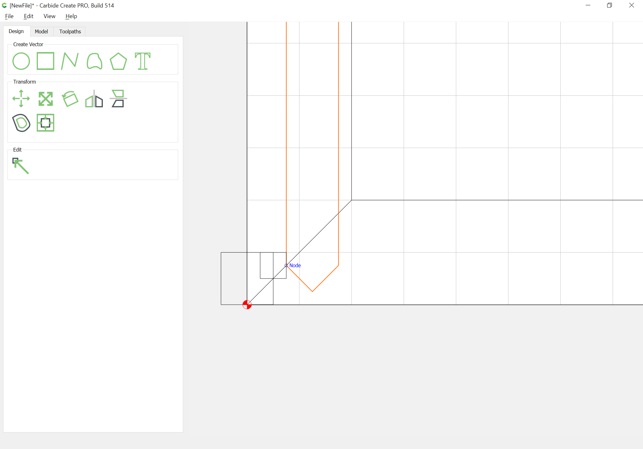
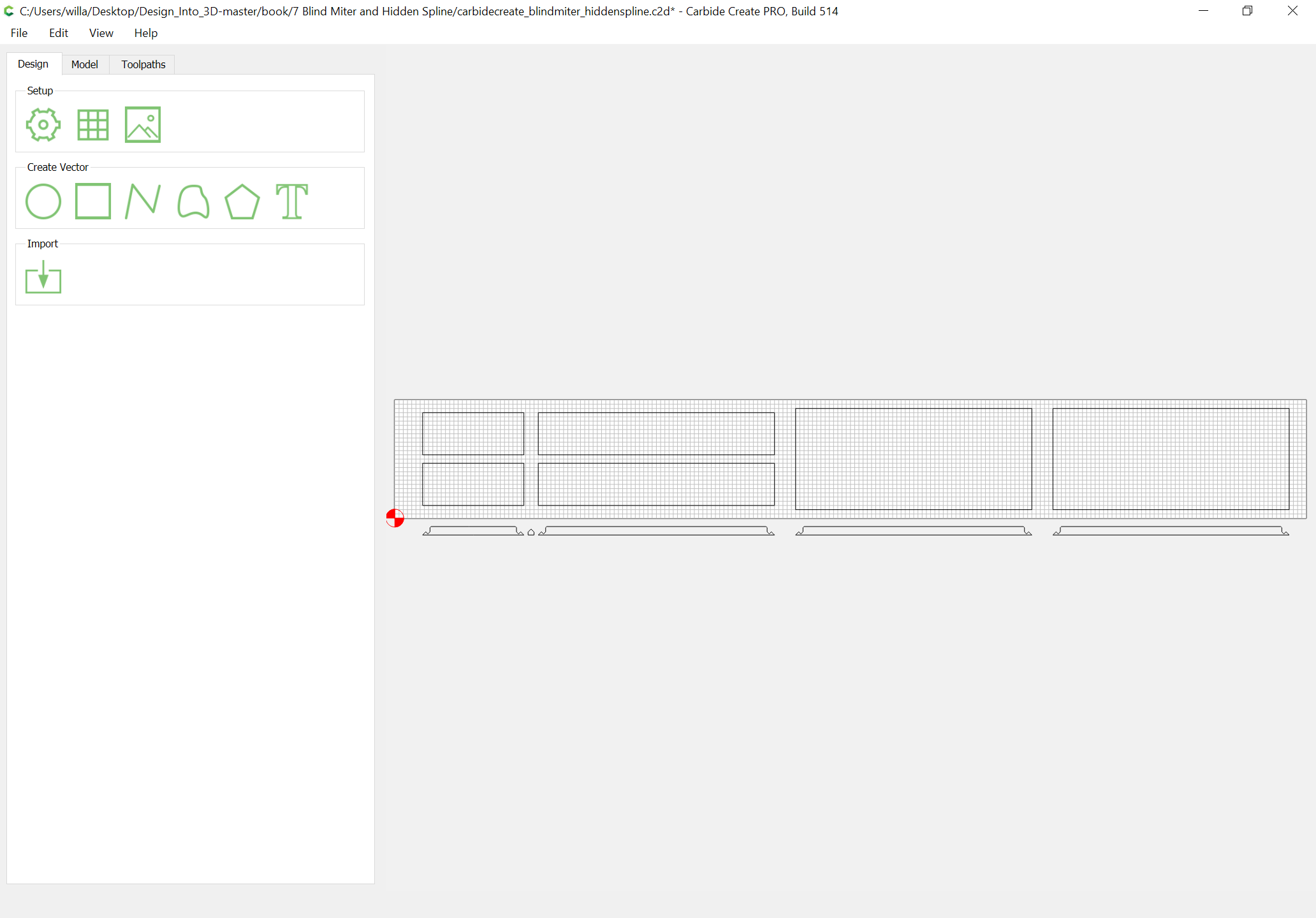
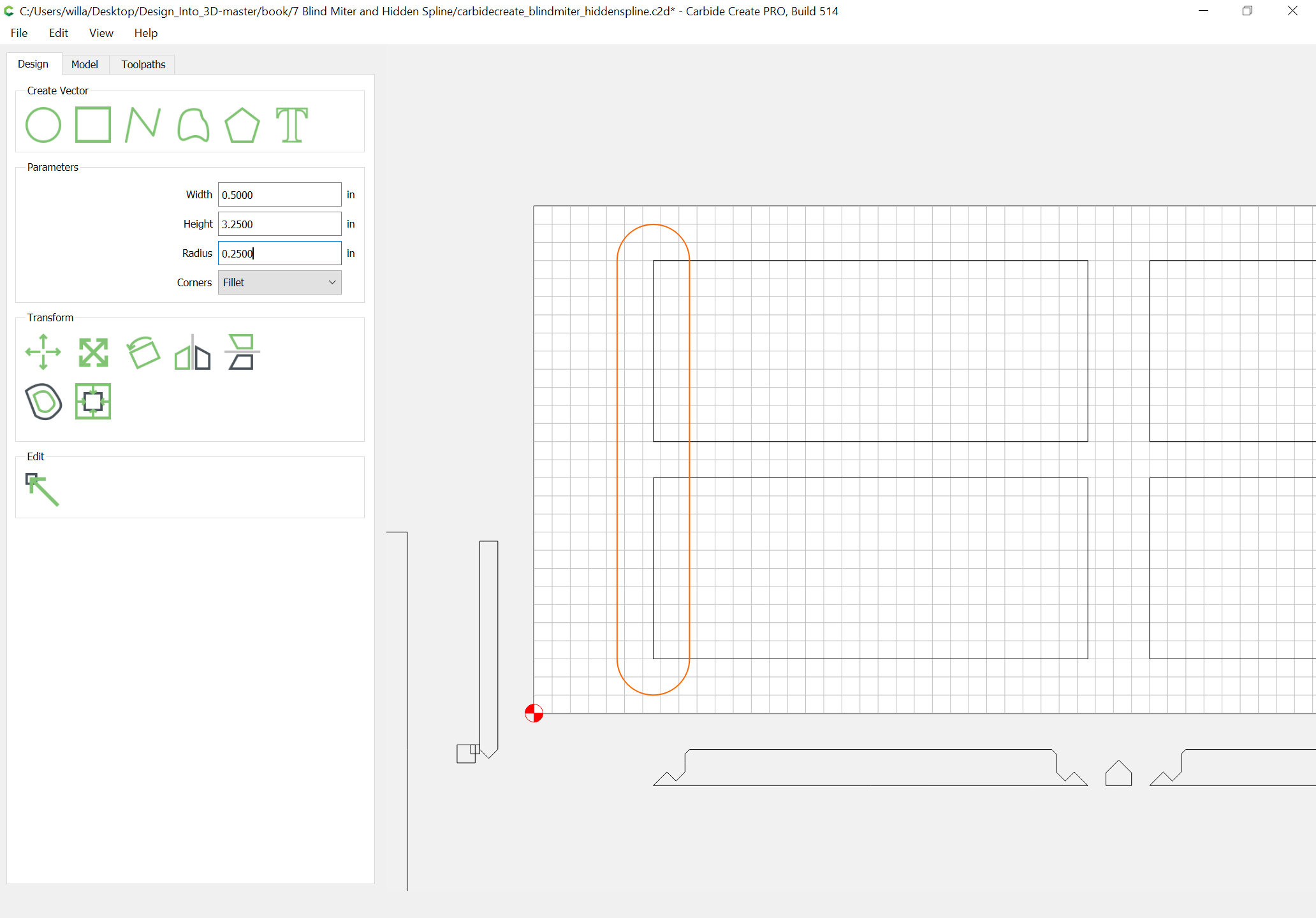
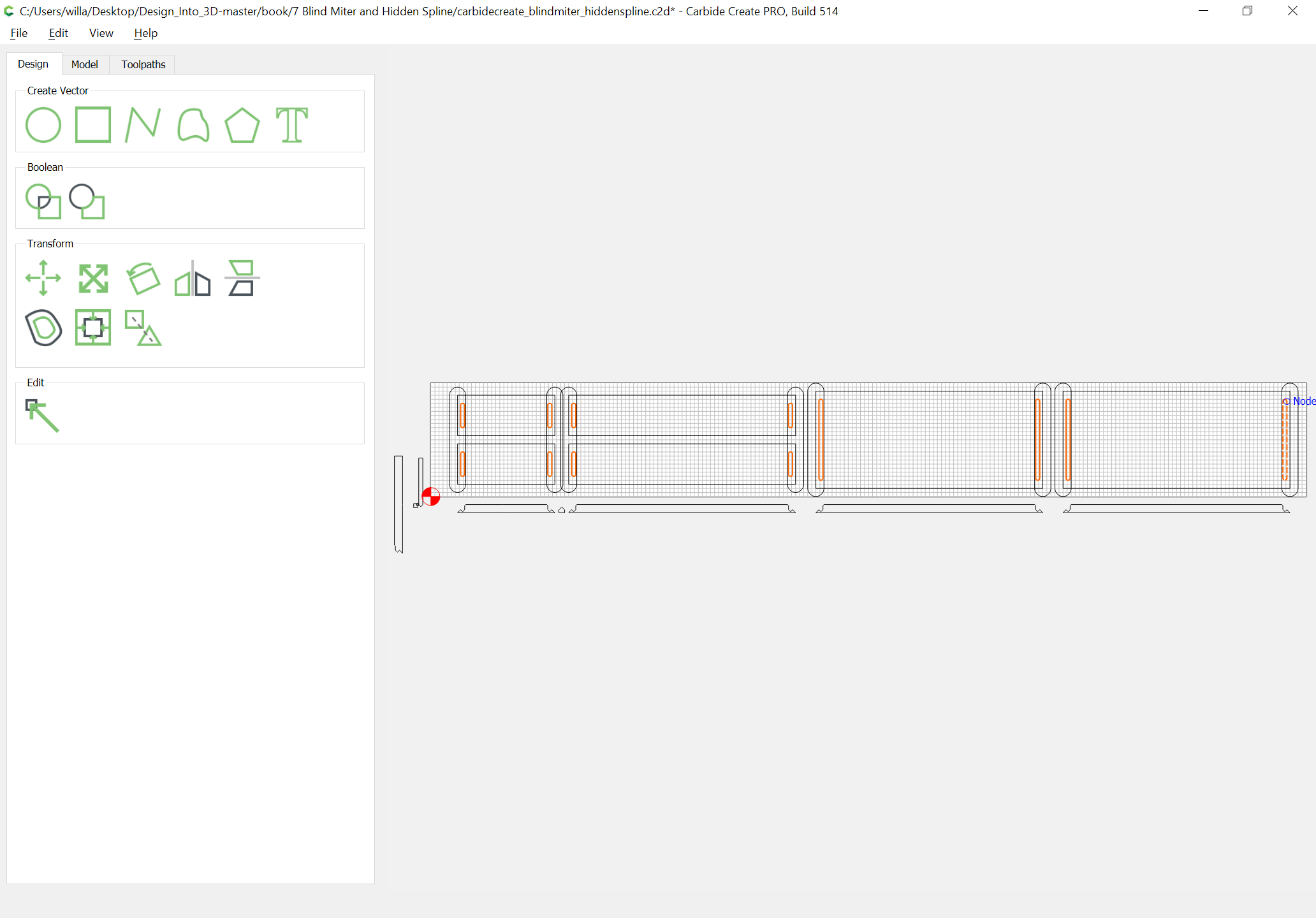
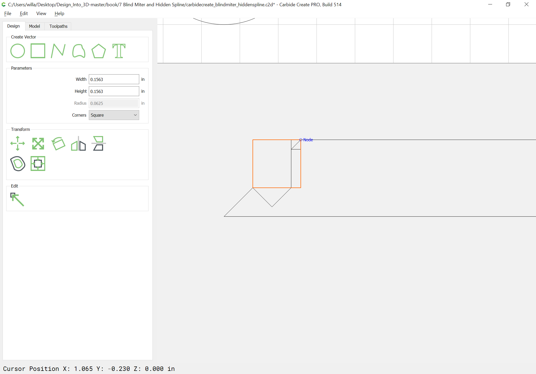
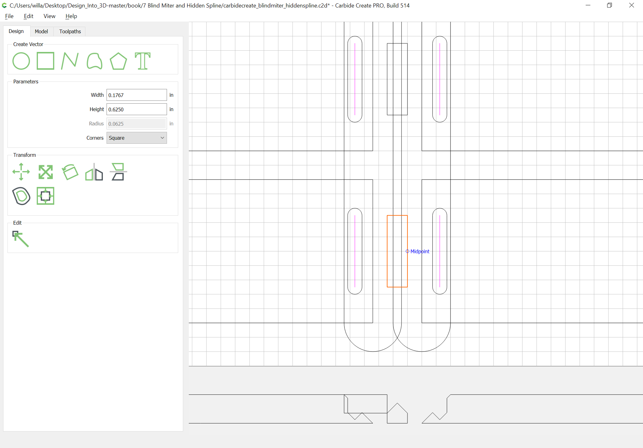
Use those to draw up suitable rectangles for all the parts (and increase stock size as appropriate), then duplicate the profiles relative to the parts in question — doing that last is greatly assisted by drawing up the profile which must needs be removed:
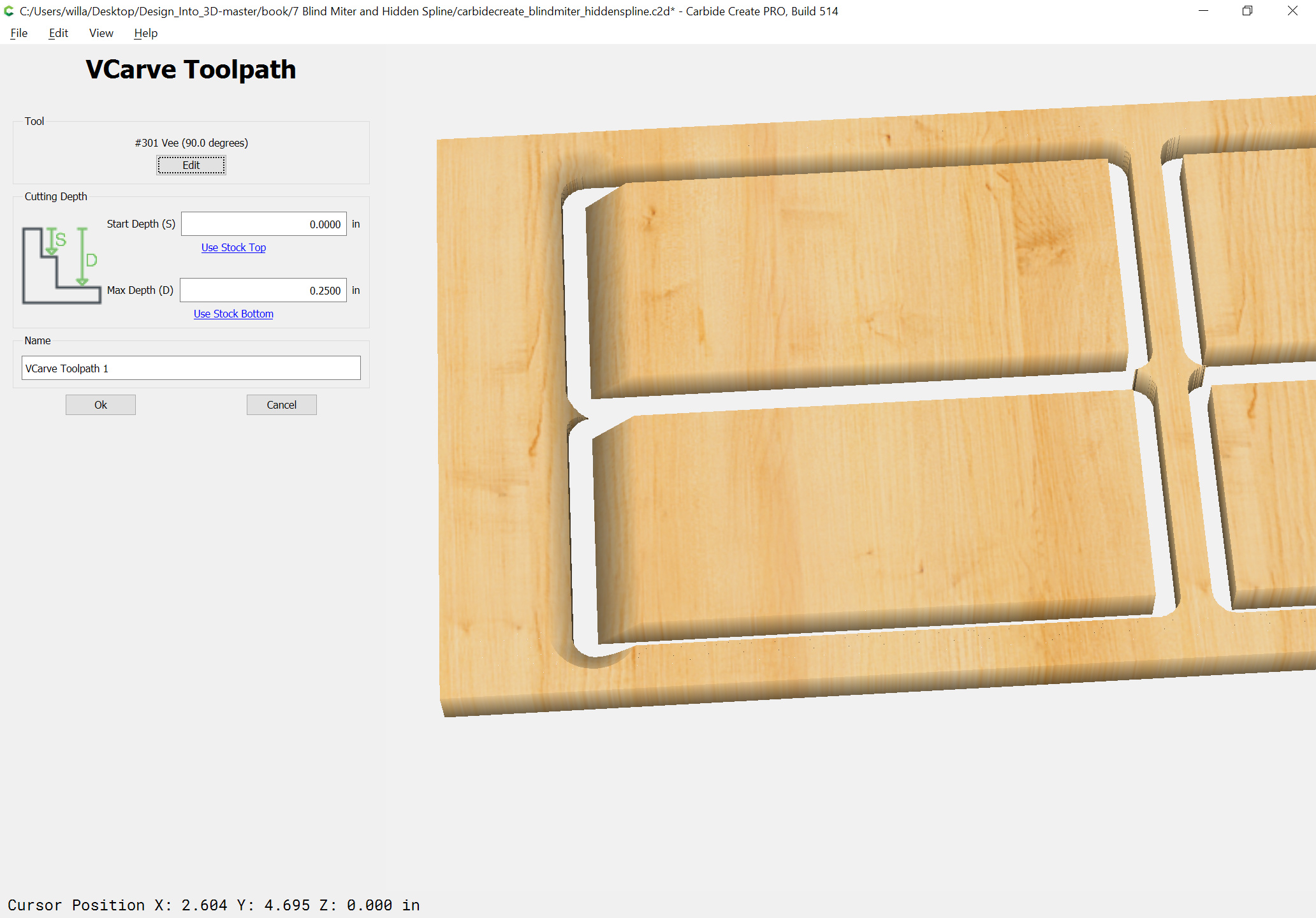
but, due to the limitations of fitting an endmill into geometry, those paths will not work, so the paths must be specified in some other way. Since the V carving operation with the larger tool will be run first we can just draw in the desired toolpath and use a no offset toolpath:
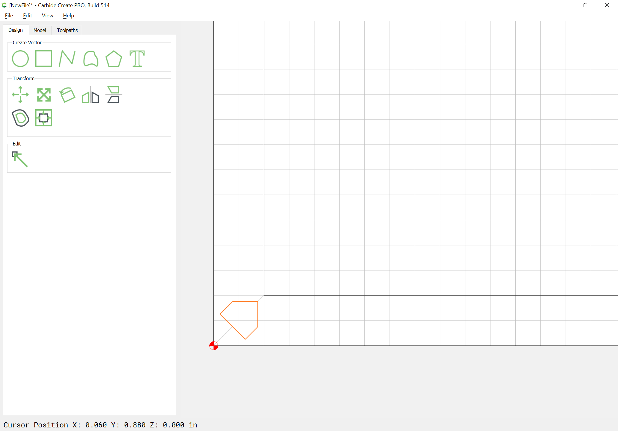
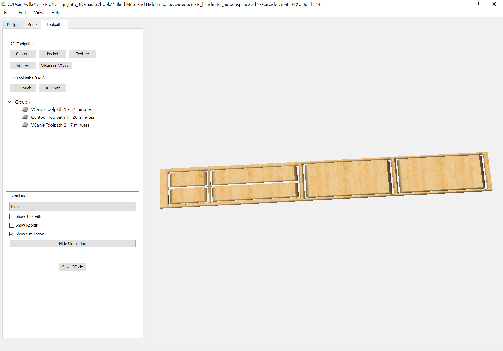
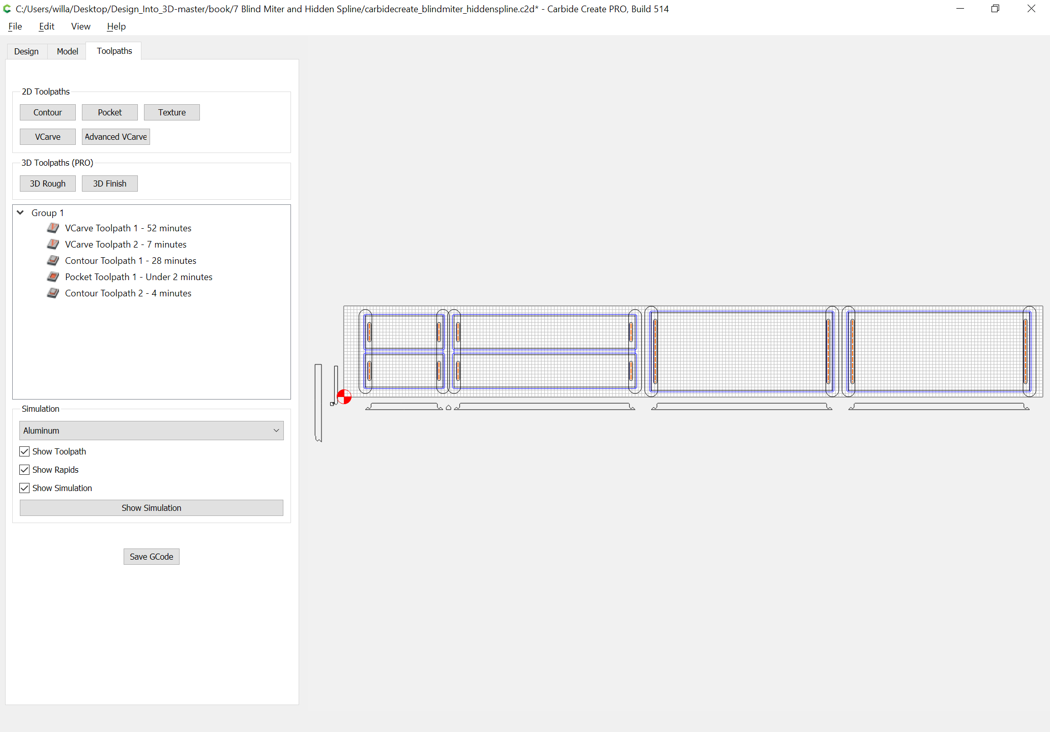
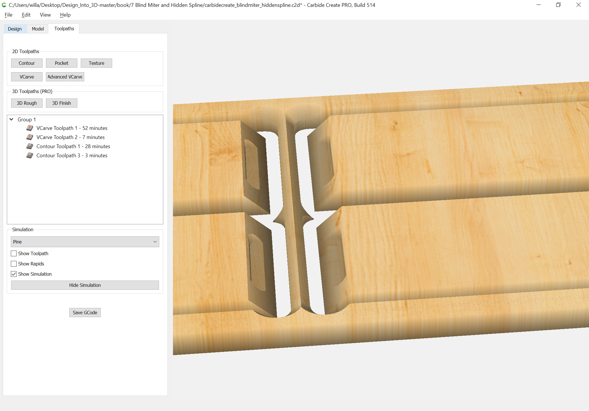
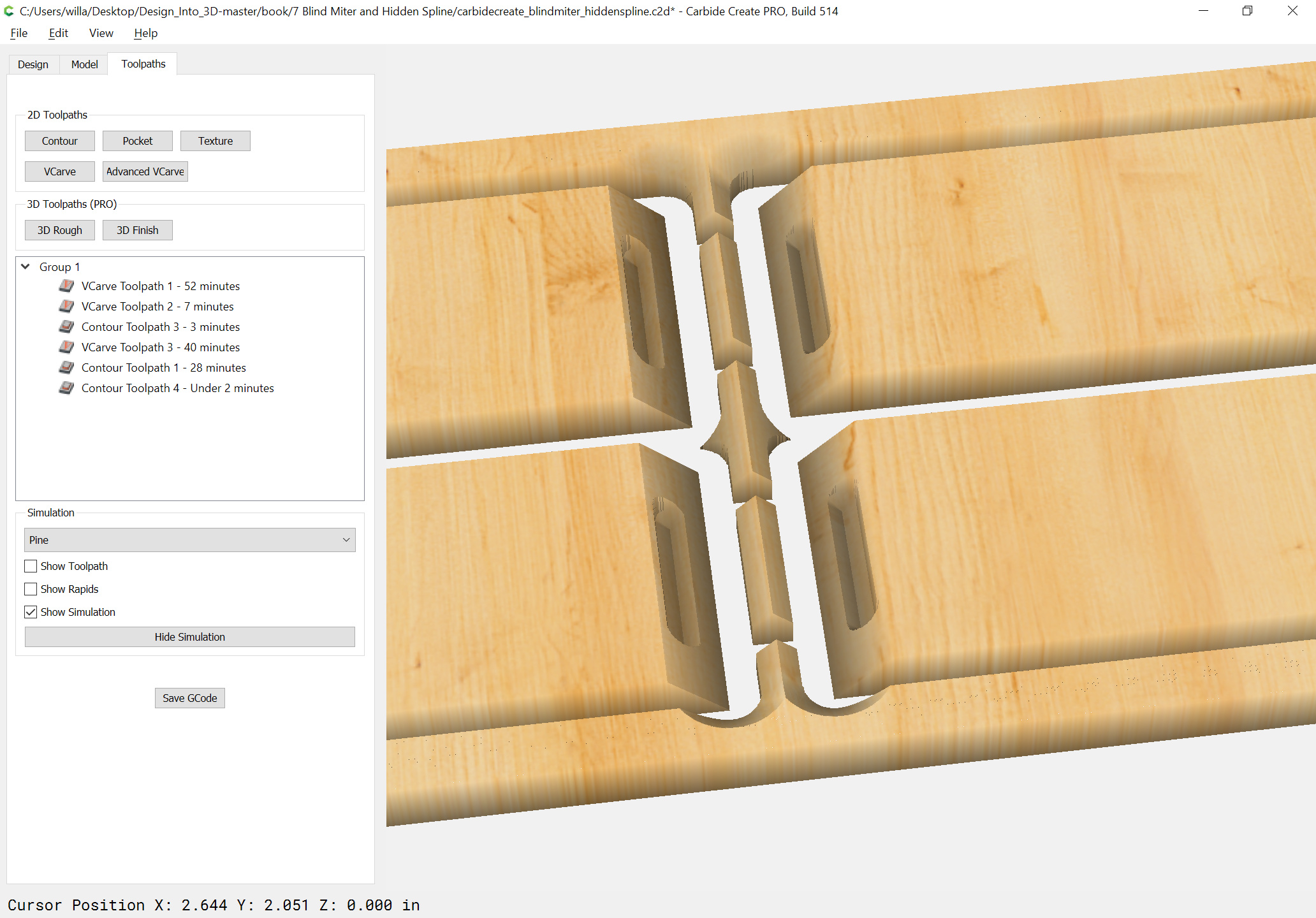
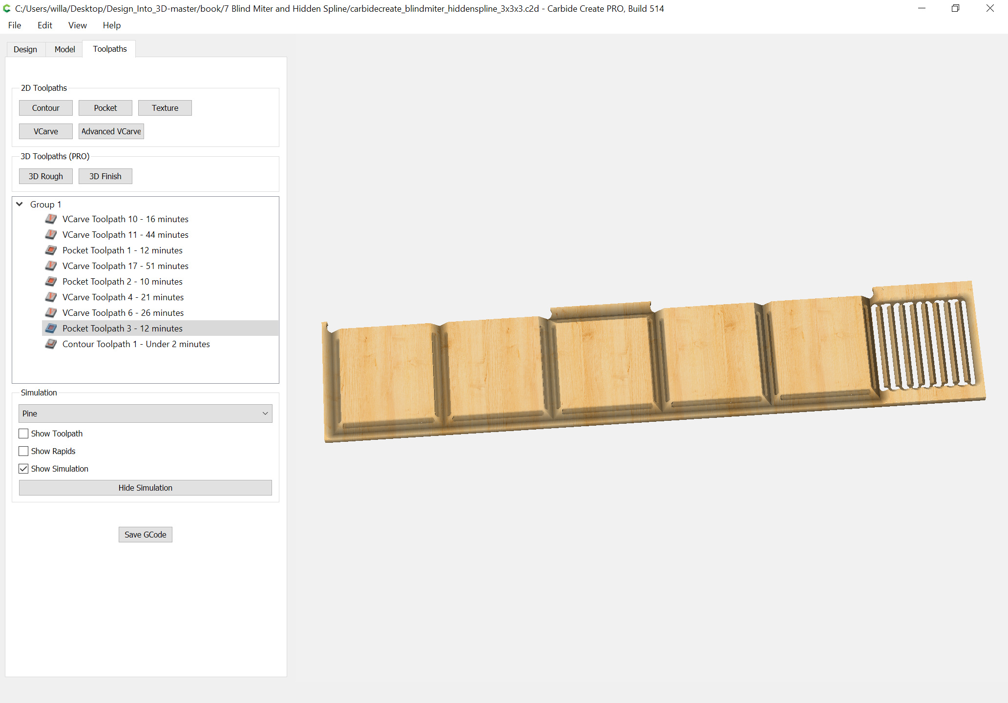
It should be possible to cut out multiple splines across the board, and their height would be controlled by distance to/from the adjacent boards (hence the desirability of doing all this programmatically).
This shows though that given some basic shapes and relative positioning it is able to create the joinery for this with what should be a good fit. Note that there will be a void to either end of the spline — modeling this in 3D is interesting, but not really machinable, though 3D printing a spline using a material such as Laywood is an interesting idea.
Next is modeling in Block/OpenSCAD and working out how to get the necessary outlines.