Im curious about the step over for a v bit. I bought a v bit with a .005in top, so would that make the step over. 0025in? I feel like that would make sense if i was just barely scraping the wood surface with the tip, but if i plunge a v bit in a ways the cut width changes. So should i be trying to calculate what that cut width is and make my step over based off that. Or do i just leave it at tip width.
Im asking this based off an1 advanced vcarve toolpath where my v bit still has some clearing left to do
My understanding is you select the v-bit and depth of cut and Carbide does the math for you to get the width of your cut (at the surface of your material). Stepover is how far it moves at the tip. I have done some advanced v-carves where the v-bit had to clean up some narrow spots at the bottom the endmill could not get into. I kept reducing the stepover until the ridges on the bottom of my pocket disappeared.
I have had success checking in the CC simulation. I had to zoom in a bunch but kept seeing little artifacts. I thought they were just random pixels but as I kept reducing the stepover for the v-bit they went away. When I cut the piece, it worked great. It takes more time because of so many passes with a tip that is so narrow so I invested in some 1/16” end mills and have some 1/32” on my list if I keep making super-detailed projects.
That rounding is small enough to be discounted — Carbide Create does not have a facility for including larger rounding of a V tool.
I dont think i fully understand what youve said. Does that mean tip size just doesn’t matter when it comes to a v bit? I suppose i couldnt calculate what the cut width would be at on my v bit at a certian plunge depth and make a step over at 30% the width because then id have little groves at the flat depth. Is that a correct way of thinking?
Tip size doesn’t matter if it is so small that it doesn’t matter and the tool may be entered using only the angle and the tip size not considered.
If a tip size is a significant percentage of the tool diameter, then it will not be possible to enter it into Carbide Create in such a way that the V cut geometry is accurately represented because tip diameter is not a parameter which can be entered into current versions of Carbide Create.
That makes senses, thank you.
To add what @WillAdams said some people have vee bits that have a round nose at the tip. That still works but it will cut deeper than you think. The reason is a vee bit in CC and CM is thought to have a sharp tip. When the tip is rounded and you use a BitSetter CM and the BitSetter think it is measuring from the sharp tip and not a rounded tip of a vee bit. That would cause depth of cut issues when cutting to a certain depth.
When doing a simple vcarve the tool path takes the vee bit down the center between two lines. The vee bit will go as deep as necessary to touch both sides of the lines. So when doing a simple vcarve you should use bottom of material to get a complete vee cut. If you limit the depth on a simple vcarve you can and will get distorted corners on letters and other objects. So always use the bottom of material on a simple vcarve to get a complete carve. Just be careful that for wider lines you dont plunge through thin material.
If you need to limit depth you use advanced vcarve. A flat end mill will carve out the flat bottom in areas big enough for the end mill to fit into. Then the vee bit goes around the perimeter of each object. If areas are too small for the flat end mill then the vee bit will do the clearing. That works but can be a rougher finish than a flat end mill would leave.
Simple answer is, Yes, set your stepover to 0.0025 or less for a rounded tip. If the tip is flat you could go as high as 0.005, but I would go 0.004 for a little overlap.
In advanced V-Carve, the stepover only applies when the V Bit is clearing the corners out where the clearing tool couldn’t reach.
A V bit with a tip will not carve deeper. The tip of either bit will be at the same Z position.
A V bit with a tip will carve WIDER than the virtual bit in CC that assumed a sharp point.
This is what the tools will look like in a cross section at any given point in the program
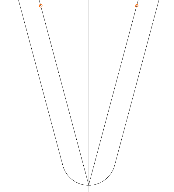
The sharp V bit in the center will run along the programmed vectors (orange circles) and adjust the depth to achieve that width. The bit with the rounded tip will end up cutting the vectors 0.005 wider.
If you are concerned about the accuracy, or your vectors are pretty thin, or you end up with goofy looking corners where the bit picks out the corners, then you can offset your vectors 0.0025" inside and use the offset curves.
1 Like
This topic was automatically closed after 30 days. New replies are no longer allowed.