Hi, I’ve been doing a decent amount of v carving inlays but have run into an issue and could use some help solving it. I’m using Vectric vcarve software for the tool paths and a 30 degree v-bit with a 0.020” flat on the tip. 0.008” stepover, full DOC (.27”), 12ipm feed, 8ipm plunge, 18000 rpm. 99% certain the v-bit is setup properly in the software.
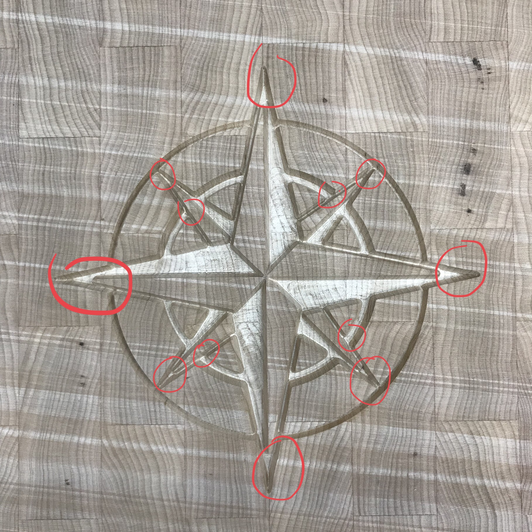
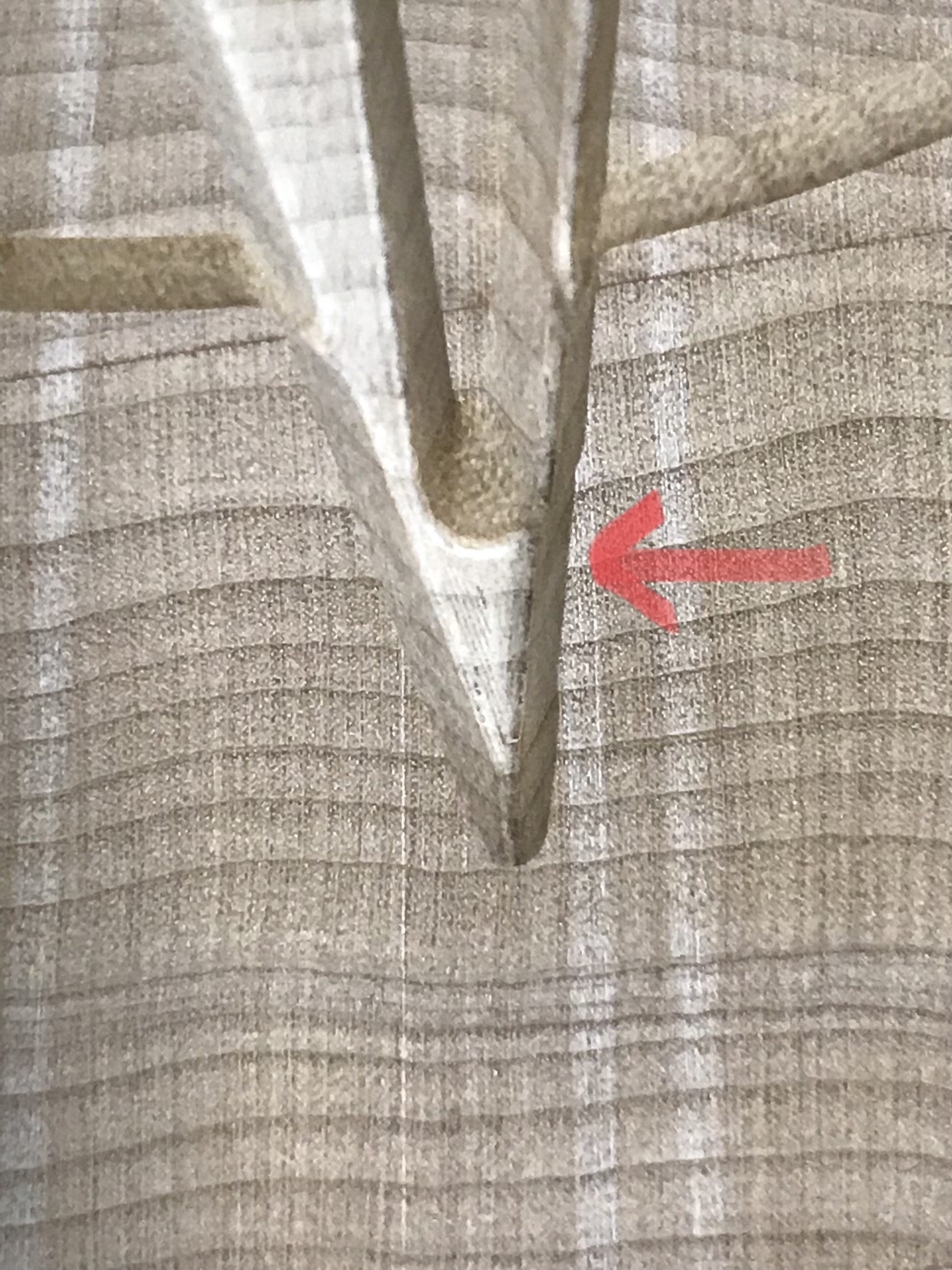
In this one toolpath I get inconsistent straight lines when the z axis is moving. I’ve attached some pictures which show the actual cut (it bumps out when it should be straight), and the tool path from 2 different angles. I’m seeing issues in all of the areas with red circles. Worst ones by far are the 4 outer points at 12,3,6,9 o’clock. I have hand calculated the horizontal toolpath offset between the different z heights and it is correct. So something in the machine or cutter is not jiving. I ran the toolpath twice in a row without touching anything, hoping it would clean up on the second pass but no luck. Thoughts? Thanks!
some mechanical failing: loose pulley set screw, eccentric nuts for the V wheels, or belt tension — uneven tension on the Y-axis belts can cause some odd difficulties
With the motors energized if I push up and down on the router mount with maybe a couple pounds of force, I can hear and feel the slightest ‘knock’… normal or worth looking in to?
The usual cause of this sort of thing is some problem in the V wheels — if it’s not the eccentric nuts and V wheel adjustment then it may be that the bearings and the precision shim and the internal race aren’t lining up properly, but check the eccentrics first:
The upper eccentric was a loose. I could spin it easily without the carriage moving. Tightening it stopped the slight ‘knock’ and will report back if it fixed it the issue.
I work with different hardwood metals and I have had many problems of cutting quality. How have I been solving my problems? The first thing I did was to square the S3 as Winston Moy does in a YouTube video that I did not find today to place the link. And the problems continued, disarm everything and check each part, I found the problems in the v-wheels and the belts, v wheels have some play and others the inner washer with different sizes so leave toas the same, the belts leave them with the same tolerance and temper, everything improved, the z-axis the belt adjusted as strong as I could but still with problems of depth cut not as much as before. For that reason I think that the z axis must be screw and not belt. I ask the support@carbide3d.com to release the CM software in order to use the screw and that our machine improves. I had similar problems that today with the mentioned adjustments have been solved.
Thanks. Squareness is good. I spent a month dialing it in before I ever used it and had it within .002” variation on 4” circle diamond squares. Plus I don’t see how squareness would have any play here? It’s making a .010” step in 2mm of travel. Even if it was grossly out of square it should still be a straight line, just not the right straight line. I’m pretty sure It’s either not getting the right z height or there is slack or backlash in the x-y…?
The paths shown on the second image looks like you should expect some level of indent there? I’m not well versed in vcarve, but the top right section looks like it curves in slightly before another straight line on the triangle cut out section. Can you modify the path bring that section out another pass?
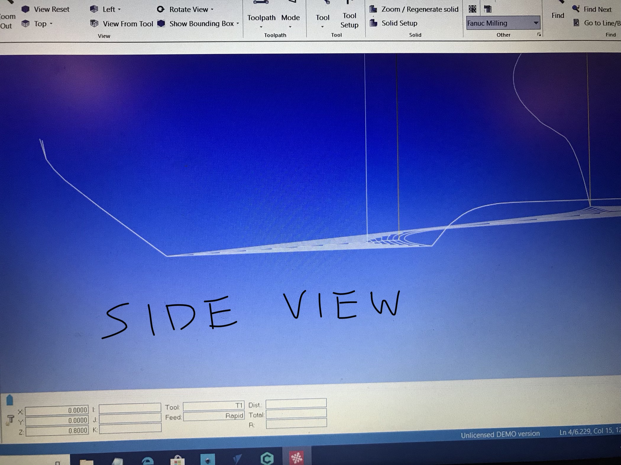
Josh, thanks for your input but the program is correct. It’s a tapered bit and it is changing z heights (4th image shows this). In order to keep a straight line up at the surface, it has to move over in x&y when the z height changes because the effective cutting diameter is changing at the surface. I hand calculated how much it needs to move over based on the angle of the bit and the change in z height, and it is correct.
@Lewscrew not yet. I thought about that as a cause but if the angle is off I’m assuming that the cut would be good at the bottom of the pocket (tip of tool) and get worse as it moves up the wall to the z0 surface. In this case the bump out is consistent from the z0 surface all the way down to the bottom of the pocket. If the tip was chipped off it could also do something like this, but it isn’t chipped.
@neilferreri yes good point but that is taken into account in my case. I use an Amana v-bit with a 0.020” tip. I have it setup in Vectric Vcarve as such so it should be a part of the tool path calculation. Now if the tip broke then it would throw things off but I’ve compared it with a new one and it’s still good as far as I can see. And I believe that situation would cause an over cut not under cut. It’s not material surface flatness. It’s happening in every part of the program where this type of geometry is present (trying to cut a straight line at the surface with different z heights).
Looking at your tool paths further, the bit is following the toolpath generated by VCP. I suspect that your vectors are not wide enough for your V-bit to reach the full cut depth. Preview in VCP is very accurate. Does this show up in the preview of the toolpath in VCP?
If you create a V-carve with say a 30’ bit or 22’ bit, do you still get the same output? If so, check your vectors in node edit mode and see if there is anything off or not what you are expecting.
Have you contacted Vectric support or posted on the Vectric forum?
@Lewscrew thanks a lot for looking! You are correct in many places the tool does not reach the full depth of cut, including the place just above where the bump out is. That is why the z height is changing. In the place where the material juts out, it is at full depth (where the tool path triangles are it is clearing out the full depth because the rougher didn’t fit in there). For the bump out either it’s not actually at full depth or it has moved over too far. I could put a depth gauge on it and measure it to see if it’s at full depth. I find the preview in vcarve (desktop) to be very grainy. It was hard to see if it was there or not but leaning towards not. I’ve checked the nodes (I drew it) and there are no nodes in that area it’s just a straight line. I calculated how much the tool needs to move over based on the tool angle and change in z height, and came up with the exact same distance that I measured in VC between the tool paths. I haven’t tried the Vectric support channel yet.
One possibility here — if you hold down the shift key when creating a new file, you’ll get access to a higher precision mode which may improve how well things cut.
Could you try making a pair of very simple geometric shapes in a bit of scrap? Say an outlined square, and star? That might help to make it obvious where the problem is.
Also, are you using Vectric’s depth-limiting feature for V carves?
Have you tried leaving a roughing clearance and making a finishing pass?