Please understand that I am not claiming to be an expert or even fully knowledgeable of vacuum tables. This tutorial is directed towards myself and is provided hopefully as a helpful aid to anyone else, so comments are appreciated.
I make wooden toys and each toy has many wooden parts, for example my wooden walking toy has 260 parts of which only 9 are stationary within the toy (yes 251 moving parts), currently only the working prototype has been made because cutting these parts is mind boggling repetition and is the main reason I started this CNC adventure. My goal for “my” vacuum table is to be able to cut many small parts from a panel of wood repeatedly cutting many identical panels of many identical small parts (production) and to than have many panels of many different parts all to be cut as easily as possible. Clamping, onion skin and tabs all add too much extra effort (IMO) to the endeavor and holding all the cut out parts and the waste to the table with a vacuum table has been accomplished by many. But I need the ultimate in variable hole patterns which is not a reasonable desire. The holes for the vacuum table need to be in some type of grid pattern, so what I need are custom vacuum table setups for each particular panel of parts. So I am building “panel vacuum templates” or custom vacuum table tops for each panel of parts.
I will not be explaining any vacuum table designs because there are many options that require your own particular needs and plans are available which I also hope to build in the future. The vacuum table itself can be any design, What I will describe is a series of vacuum table top templates for repeat cutting and easy realignment after switching panel templates. My current vacuum table consists of a pump, a vacuum gauge, a quick disconnect (like on an air hose) and the vacuum table itself with a grid pattern of holes. I am a terrible photographer so all my pictures are sketchup drawings which are easier to annodate.
So here we go…….
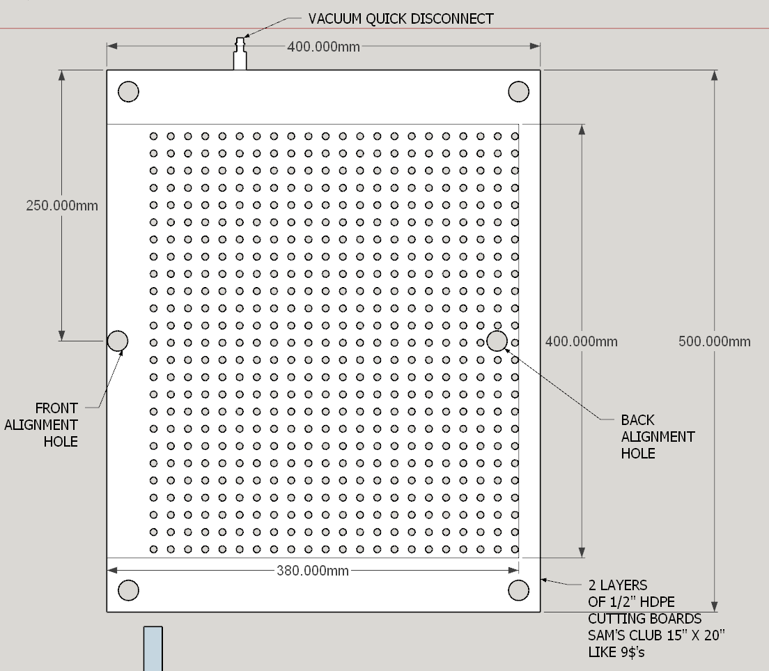
Here is a picture of my vacuum table with the disconnect at the top edge. It is sized for my Shapeoko 3 and I can slide it in or out of the machine when ever I want without rebuilding or messing the machine up, because I have 2 alignment holes in the center of the front and back, the 4 corner holes are just there. The 2 alignment holes are the same as described in my last tutorial and will maintain that same alignment process within the vacuum holding system process.
Next is a drawing of a simple panel of parts, only 4 but fairly complex because there are holes in the parts that need to be machined but must not interfere with the vacuum hole grid pattern.
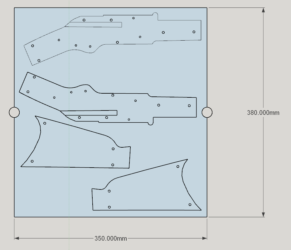
As you can see with an overlay of the vacuum hole grid pattern over the parts, there are many holes which interfere or that will interrupt the vacuum holding the parts.
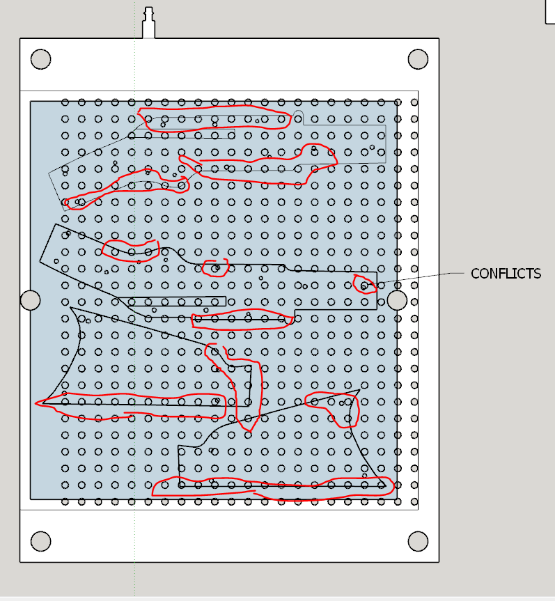
I need to support the panel on both sides of the kerf being cut and provide a groove for the vacuum suction holding the interior of the part being cut out. And of course, the next panel will include other conflicts with the vacuum grid hole pattern which is why I need individual templates for each individual panel. To solve this delima, I will build the templates with 2 layers of tempered hard board contact cemented together. The top layer will have the vacuum suction grooves located inside the outline of the parts providing support to the edge of the part being cut and suction directed only under the part itself.
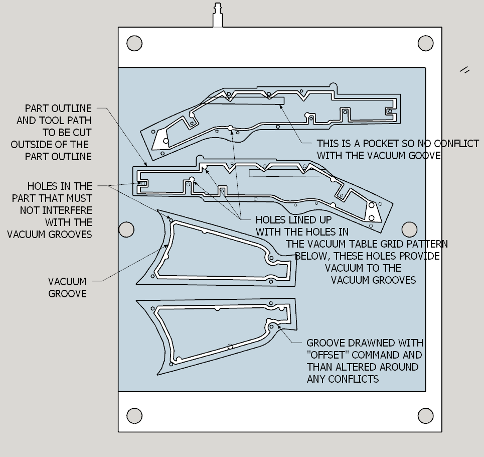
The top hard board layer will also have holes lining up with the vacuum grid pattern for holding the waste in place.
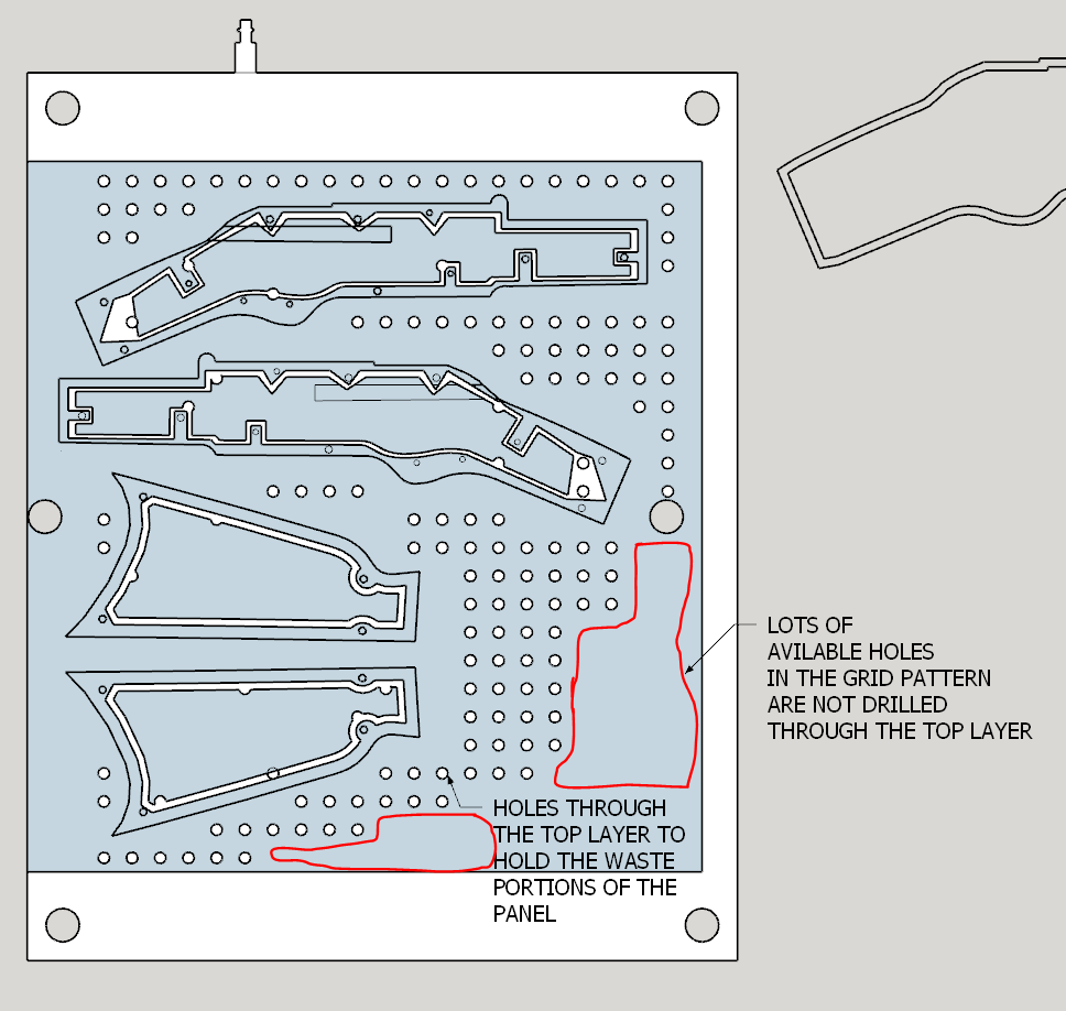
Not all available holes outside of the parts being cut are drilled through the top layer, as you can see. Now there is also a bottom layer of hard board which is glued to the top layer. The bottom layer only has holes which line up with the holes in the top layer and those areas without holes allow the vacuum suction from the vacuum table grid pattern to hold down the template without clamps and aligned by the 2 “centered” pegs. The main purpose of the bottom layer is to secure the portion of the top layer that is cut by the vacuum grooving, this interior portion is what supports the individual parts after being cut and the vacuum groove holds the cut out part to the template.
Now there is one outstanding property of the templates and vacuum table to finalize, a “rubbery” layer to seal the templates to the vacuum table itself and a rubbery layer on top of the template to seal the panel to be cut to the template. One member has used that “flex seal” spray successfully. I’ve tested several other methods and only the rubber weather stripping has succeeded. The weather stripping has a history of coming loose after a while so I will be trying either flex seal or another “rubber” paint rolled on in several coats. A paint solution will allow even distribution and a full surface seal whereas the weather stripping will introduce an air gap between the template and the panel along with an air gap between the template and the vacuum table top. So a rubbery paint wins.
One final reason why I chose to use tempered hard board for my templates, I can glue the 2 rough sides together creating a tempered side on both sides of the template and seal them with the rubbery paint, and any warpage can be removed by the vacuum since they are fairly flexible in nature anyways.
It is true that making individual templates increases the time creating a project but that time will be well spent (IMO) when I am able to cut multiple panels of parts without the fuss of clamping and the extra effort required to remove the onion skin and/or tabs. The tool paths cut first most of the ways through with one tool and finish the through cut with a smaller tool to minimize the cutting forces on the vacuum table. To absolutely avoid tear out I cut the outline with a vee bit only 1mm deep to separate the top veneer from the actual cutting through of the panel and produces a “chamfered edge”. This is an additional step with extra time but since it is a surface only vee cut, it does take less than 5 minutes in which the result pays the dividend for the extra step.
So than I will be able to cut several panels of one template, turn off the vacuum, install a new template over the 2 alignment pegs, slap on a new panel, turn on the vacuum and cut cut cut. Like a machine!
The final and only question is whether or not my 35 year old 3 cfm vacuum pump will hold all this down. My A/C buddy says it will as once a vacuum is established, breaking the seal is the only way to move the panel which is why a full surface seal (a rubbery paint) will work better than weather stripping or even the rubber cordage (which also requires a separate groove) as the entire surface will be sealed rather than just a “line”. How fast this old pump will establish the vacuum is questionable but not my main concern as I don’t work “by the hour” anyways. There is very little cubic feet of air to be removed by the pump so it really shouldn’t be “coffee break time”.
I hope this gives some insight into the various ways to utilize a vacuum table. It will solve my problems (IMO).
As always Your Mileage May Vary and any and all comments are welcome. Your friend and fellow member Grumpa (Jude) and Happy CNC’ing.